Note: Descriptions are shown in the official language in which they were submitted.
CA 02368219 2001-10-05
WO 00/59579 PCT/FI00/00298
1
A BARRIER APPARATUS FOR RESISTING PASSAGE OF HARMFUL GASES
THROUGH AN OPENING
BACKGROUND OF THE INVENTION
The invention relates to a barrier apparatus for resisting passage of
harmful gases from a space through a substantially vertical opening having a
top, a bottom and lateral sides, the barrier apparatus comprising a suction ar-
rangement for sucking gases and blowing arrangement for creating a flow of a
medium.
A barrier apparatus as described above is known for example from
the International Patent Publication WO 93/10861. This reference discloses
spray heads mounted above a doorway and arranged to produce a fog-like
curtain of water. The spray heads operate at a high pressure, i.e. over 50
bar,
and they produce in their immediate surroundings a high negative pressure
that sucks smoke gases into the water spray. When the smoke gases are
mixed with the spray, which preferably comprises a huge number of small
droplets of water, the particles in the smoke gases are absorbed into the
spray, thus mixing with the water droplets and being purified. With this
method
the harmful effects of poisonous gases have been greatly reduced. Another
advantage is that when spray heads are arranged in small spaces, such as
ship cabins and hotel rooms, smoke gases can be prevented rather effectively
from spreading outside the small spaces, for example to corridors and further
to other spaces.
The barrier apparatus disclosed in WO 93/10861 has been found to
be especially effective in preventing smoke from spreading from small rooms
to other spaces. Due to the operation described above, the barrier apparatus
are also used to extinguish a fire. However, the spray means are not particu-
larly applicable for use in large spaces, i.e. when smoke should be
effectively
absorbed and purified in big spaces.
The invention also relates to a method of guiding and processing
harmful gases, especially smoke gases produced in a fire, near a substantially
vertical opening, especially a doorway, and in a space comprising the harmful
gases, in which method a flow of medium is created in the immediate vicinity
of the opening.
WO 93/10861 discloses a method for guiding and purifying smoke
gases near a doorway. Smoke gases can be guided and purified effectively
when the spray means are located in a rather small space, which is subjected
CA 02368219 2001-10-05
WO 00/59579 PCT/FI00/00298
2
to a fire and should thus be purified of smoke gases. However, if the space
that should be purified is large and there is no fire, the purification of
smoke
gases is not as effective as it should be.
BRIEF DESCRIPTION OF THE INVENTION
An object of the invention is to provide a barrier apparatus and a
method enabling effective processing or treating, even in a large space, of
harmful gases, such as smoke gases produced in a fire, and other poisonous
gases so as to reduce the harmful effects thereof.
For this purpose, the barrier apparatus according to the invention is
characterized in that
the suction arrangement comprises at least one suction port located
near the top of the opening to provide suction substantially along the width
of
the opening,
the blowing arrangement comprises at least one blowing port lo-
cated near the bottom of the opening to provide blowing substantially along
the width of the opening,
a fluid coupling coupled between the suction arrangement and the
blowing arrangement being provided and defining a fluid path between the
suction port and the blowing port, a spraying device being arranged in the
fluid
path for driving gas from the suction port to the blowing port and being ar-
ranged for spraying a liquid in the fluid path for purifying and/or cooling
media
flowing through the fluid path.
Preferably the suction arrangement comprises a top suction duct lo-
cated along the top of the opening and comprising said at least one suction
port, and a first side suction duct and a second side suction duct located
along
opposite lateral sides of the at least one opening in the upper region
thereof,
and each side suction duct comprising at least one side suction port at a
level
below said at least one suction port. Such a construction makes the apparatus
efficient and simple.
According to a preferred embodiment of the invention, the spraying
device is arranged to spray liquid in the form of a fog-like spray. The fog-
like
spray purifies gases, e.g. smoke gases produced in a fire, very efficiently.
Preferably the spraying device is a spray head located in a side
suction duct.
Preferred embodiments of the barrier apparatus are described in
the appended claims 2 to 9.
CA 02368219 2001-10-05
WO 00/59579 PCT/F100/00298
3
The sucking is carried out near the top of an opening, which is very
advantageous when applying the present invention for purifying smoke gases
produced in a fire. These smoke gases are hot and move therefore upwards
and are likely present near the top of the opening.
The method according to the invention is characterized in that in an
upper area of the opening in an area substantially corresponding to the width
of the opening gases are sucked from the space into at least one suction port,
and that near a bottom area of the opening in an area substantially corre-
sponding to the width of the opening purified gases are blown from at least
one blowing port into the space, said suction and said blowing being directed
so as to at least substantially prevent air from penetrating via the opening
into
the space.
Preferably the gases are guided above the opening and the me-
dium is sprayed near the very bottom the opening.
Preferably in upper parts of the lateral sides of the opening gases
are sucked from the space into further suction ports and from a level below
said at least one suction port and above the middle of the lateral sides of
the
opening.
When applying the method for guiding and purifying smoke gases
produced in a fire, preferably a fog-like medium is sprayed with a spraying de-
vice at a high pressure to establish a flow path between said at least one suc-
tion port and said at least one blowing port and to provide the suction into
said
at least one suction port and to provide the blowing from said at least one
blowing port, smoke gases being guided by said suction into the fog-like me-
dium discharged from the spraying device in order to absorb in smoke gas
particles. The fog-like medium is preferably an aqueous medium.
A primary advantage of the invention is that harmful gases can be
effectively transformed into a harmless form even if they are produced in a
large space. When the invention is applied to extinguishing a fire, an
important
advantage is that the suction of air via the opening towards the fire is pre-
vented rather efficiently, which greatly contributes to putting out the fire.
Oxy-
gen poor purified gases are blown through the blowing port towards the space
to be purified.
BRIEF DESCRIPTION OF THE FIGURES
The invention will be described below in greater detail by means of
two examples with reference to the accompanying drawing, in which
CA 02368219 2001-10-05
WO 00/59579 PCT/F100/00298
4
Figure 1 is a front view of spray means arranged around a doorway,
Figure 2 is a side view of the spray means of Figure 1,
Figure 3 is an end view of a spray head,
Figure 4 is a longitudinal view of the spray head according to Figure
3, and
Figures 5 and 6 show a second embodiment of the invention.
DETAILED DESCRIPTION OF THE FIGURES
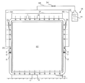
In Figure 1, a doorway 20 is surrounded by a rectangular pipe sys-
tem. The pipe system comprises a top suction duct in the form of a horizontal
pipe section 10, a bottom blowing duct in the form of a horizontal pipe
section
11, and side suction ducts in the form of vertical pipe sections 8 and 9 con-
necting the horizontal pipe sections. The aforementioned pipe sections 8 to 11
are provided with such lengths that the rectangle they form is slightly
greater
than the rectangle formed by the doorway, so that the pipe system in the
doorway does not prevent the installation of a door therein, or passage
through the doorway. The doorway may, particularly if it is high, also be
higher
than the pipe sections 8, 9: reference numeral 21 is drawn to such a doorway.
The pipe sections 10 and 11 may in some applications be shorter than the
width of the doorway. The pipe sections are in flow communication with one
another. Pipe section 10 is provided along the length thereof with a number of
suction ports in the form of openings 1 facing a room 30 or other space. Cor-
respondingly, pipe section 11 is provided along the length thereof with a num-
ber of spray ports in the form of openings 5 facing the room 30. Pipe sections
8 and 9 are provided with side suction ports in the form of openings 2a and
2b,
respectively, facing the room 30. The suction openings 2a, 2b are formed
above the middle of the respective pipe sections 8 and 9 so as to extend sub-
stantially to the elbow of the pipe system. The suction openings 1, 2a, 2b and
the spray openings 5 are formed on the walls of the respective pipe sections
10, 8, 9 and 11. These openings 1, 2a, 2b, 5 are directed for sucking and
blowing respectively at an angle of between 20 and 90 , preferably between
and 90 .
Inside pipe sections 8 and 9 are provided spray heads 3 and 4, re-
spectively, below the suction openings 2a and 2b. The spray heads 3, 4 are of
35 a type that is able to operate at a high pressure, typically for example
from 50
to 200 bar. In principle the high pressure can be any pressure that is higher
CA 02368219 2001-10-05
WO 00/59579 PCT/FI00/00298
than a low pressure, i.e. about 12 bar. In practice a pressure range of from
20
to 300 bar covers the entire required area of pressure.
If the space 30 is to be protected against harmful gases arising from
the space on the left side of the doorway in figure 2, a pipe system similar
to
5 the pipe system on the right side of the doorway should be installed on the
left
side of the doorway.
Figures 3 and 4 show a spray head that can be utilized in the pres-
ent invention. The spray head is provided with a plurality of nozzles 100.
When these spray heads operate at a high pressure, they spray a fog-like liq-
uid-containing medium illustrated by reference numerals 6 and 7 along pipe
sections 8, 9 and 11 to produce in their immediate vicinity a negative
pressure.
This negative pressure is apparent from a suction which prevails behind the
spray heads, said suction, in turn, producing suction in the suction openings
1,
2a and 2b. The suction is illustrated in Figure 2 by reference numeral 31. A
spray illustrated by reference numeral 32 in Figure 2 is directed from the
spray
openings 5 into the room 30.
The spray heads 3, 4 are connected via a supply line 33 to a hy-
draulic accumulator 13, which comprises a space 14 for an aqueous liquid and
another space 15 for nitrogen gas or some other gas. The space 15 for gas is
subjected to a high pressure, which makes the liquid move via the supply line
33 to the spray heads 3, 4, provided that a valve 34 is open. Unlike in the
fig-
ure, the hydraulic accumulator 13 can comprise separate vessels for gas and
liquid. A high pressure pump can be used as an alternative to the hydraulic
accumulator.
The pipe sections 8 to 11 are preferably made of steel or plastic,
and the diameter thereof varies from 30 to 300 mm, preferably from 50 to 200
mm, whereas the diameters of the openings 1, 2a, 2b, 5 provided in the pipe
sections vary between 2 and 100 mm, preferably between 5 and 50 mm. Suit-
able dimensions, number of openings, the pressure to be used, and the vol-
ume of the hydraulic accumulator 13 are selected separately for each applica-
tion. The flow resistance in the suction openings 1, 2a, 2b is preferably se-
lected to correspond to the flow resistance in the spray openings 5.
The operation of the equipment shown in the figures will be de-
scribed below.
Assume that smoke is produced in the space 30. A smoke detector
(not shown in the figures) provided in the space 30 gives a signal, which
CA 02368219 2001-10-05
WO 00/59579 PCT/FI00/00298
6
opens the valve 34 and also ensures directly or indirectly that other possible
obstacles preventing the flow of liquid from the hydraulic accumulator 13 to
the
nozzles of the spray heads 3, 4 are removed. The hydraulic accumulator 13
starts to empty and an aqueous medium moves at a high pressure to the
spray heads 3, 4 and further out of the spray heads in a fog-like or gaseous
form (cf. arrows 6 and 7). A negative pressure produced in the suction open-
ings 1, 2a, 2b sucks smoke and other gases into pipe section 10 and into the
upper parts of pipe sections 8 and 9. In the lower parts of pipe sections 8
and
9 the smoke is mixed with the fog-like aqueous sprays 6, 7 and is thus puri-
fied. The sprays 6, 7 have a droplet size of typically under 400 m. Water
containing smoke particles is discharged via a drain 12 provided at the lower
end of the pipe section 11, so that the pipe section is constantly in working
or-
der for blowing oxygen poor purified gases via the spray openings 5.
When the spray means operate as described above, the space 30
is provided with constant circulation where smoke gases are sucked into the
pipe system 8 - 11 and discharged therefrom back into the space in a purified
form.
Figures 5 and 6 show another embodiment of the present invention.
Corresponding reference numerals as in Figures 1 and 2 have been used for
similar components. The pipe system in Figures 5 and 6 is installed in the
middle of the doorway having the suction openings 1' and spraying openings
5' facing each other. Such a pipe system protects harmful gases from flowing
to either side of the doorway, although not as effectively as two separate
pipe
systems positioned on respective sides of the doorway.
The invention is described above by means of two examples only,
wherefore it is noted that the details of the invention can be implemented in
various ways within the scope of the appended claims. Thus, the shape of the
pipe system and the medium to be sprayed can differ from what is disclosed
above, and the spray means can be used more generally to process and neu-
tralize harmful gases and not necessarily to purify smoke gases produced in a
fire. Two vertical pipe sections 8 and 9 and side openings 2a, 2b are not a ne-
cessity although very advantageous. Only one vertical pipe section, even
without any side opening, can be contemplated for some applications. Natu-
rally, the number of the suction openings 1, 2a, 2b and the spray openings 5
can differ from what is described above. Instead of a plurality of suction and
spray openings, it is possible to use suction opening means and spray open-
CA 02368219 2001-10-05
WO 00/59579 PCT/FI00/00298
7
ing means, respectively, that are in the shape of an elongated slot which ex-
tend substantially along the width of the doorway. The spray opening and suc-
tion opening means do not necessarily comprise a spray head since the
spraying and suction can also be provided with other kinds of spraying means.
However, a spray head is particularly advantageous in providing the required
spraying and suction. The number of the spray heads 3, 4 can differ from what
is disclosed above: a single spray head arranged in pipe section 11 is suffi-
cient. However, due to spray heads arranged in pipe sections 8 and 9 the
structure of the pipe system can be made very simple and the operation
thereof effective. If the doorway 20 is large, i.e. pipe sections 8 and 9 are
long,
spray nozzles can be arranged in the pipe sections one after another, such
that the rear or upper nozzle sprays towards the front or lower nozzle, which
sucks in the medium sprayed from the rear or upper nozzle. With this ar-
rangement the flow resistances in the pipe sections, no matter how great, do
not form an obstacle for spraying. The geometrical form of the doorway, or
other opening through which harmful gases may not pass through, does not
have to be a rectangle: it can e.g. be circular. The purification of gases can
be
done by a filter in addition to or as an alternative to the purification by
means
of a spraying device such as a spray head.