Note: Descriptions are shown in the official language in which they were submitted.
CA 02368303 2001-09-19
WO 00/59440 PCT/KR00/00298
TRANSM ISS ION FOR WHEELCHA IR
Technical Field
The present invention relates to a transmission for a wheelchair,
and more specifically, to a transmission for a wheelchair capable of
selecting manual and motor-driven ways.
Backcround Art
Typically, the wheelchair is provided with a ring-shaped driving
wheel (or a wheel for a handle grip) on the outsides of the both
wheels thereof, respectively, which is rolled and ri~oved by using the
hand of a user.
The conventional wheelchair does not have any problem in
rolling and moving by the hands of the user, but it is found that it is
not convenient for those who are difficult to use and move the
wheelchair in a manual way. To solve this problem, a variety of
transmission wheelchairs capable of being driven in a motor-driven
way are developed.
However, the conventionally developed transmission wheelchairs
have the defects that the transmission is configured in a complicated
manner and the weight thereof is substantially heavy, such that it is
greatly restricted to the user such as a disabled person. Moreover, the
conventional transmission wheelchairs are used exclusively for the
motor-driven way, and upon demand of use in the manual way, they
are inconvenient to change to the desired manual way. Actually, due
to the heavy weight of the transmission, it is impossible to use the
manual way.
Disclosure of the invention
An object of the invention is to provide a transmission for a
wheelchair capable of providing a simple construction and all
conveniences in use, providing a unit for freely selecting manual and
motor-driven ways, making the weight thereof substantially light to
thereby prevent the occurrence of the inconvenience in use caused
due to the weight of the transmission when in the manual way, and
CA 02368303 2001-09-19
WO 00/59440 PCT/KR00/00298
-2-
improving the durability thereof and the reliability of operation.
To achieve this and other objects of the present invention,
according to the present invention, a transmission for a wheelchair
which is installed on a frame for the wheelchair and for selecting and
driving the wheelchair in manual and motor-driven ways, which
includes: a transmission unit installed on the wheelchair for driving the
wheelchair: a clamping unit for fixing the transmission unit on the
wheelchair: and a switching unit for switching the wheelchair in the
manual and motor-driven ways; wherein the transmission unit
comprises, driving rollers coupled to accelerator and decelerators
connected to motors on the both sides of the interior. of a casing, for
driving both wheels, and a controller circuit-connected to the motors,
a motor control circuit unit and a battery, for adjusting the
transmission unit, wherein the switching unit comprises, a fixing clip
assembled by means of the clamping unit with the casing of the
transmission unit and having a locking projection locked or unlocked
to/from a locking hole of a fixing part fixed on the frame of the
wheelchair, a locker elastically coupled with first and second springs
on the top and bottom portions of the interior of the fixing clip and
for pulling upward by means of a handle, the locking projection
elastically protruded on the both sides of the locker, respectively and
locked or unlocked to/from the locking hole of the fixing part, a first
pulling string connected to a push button elastically installed by
means of a third spring on the handle, for pulling the locker with the
locking projection by the pressing operation of the push button, to
thereby isolate the driving rollers on the both sides of the transmission
unit from the wheels, and a ratchet for controlling the manipulation of
the handle by means of a stopper connected by a second pulling
string to the push button of the handle.
It is to be understood that both the foregoing general
description and the following detailed description are exemplary and
explanatory and are intended to provide further explanation of the
invention as claimed.
Brief Description of the Drawing
CA 02368303 2001-09-19
WO 00/59440 PCT/KR00/00298
-3-
Other objects, advantages and details of the transmission for a
wheelchair of this invention appear in the following detailed description
of preferred embodiments of the invention, the detailed description
referring to the drawings in which:
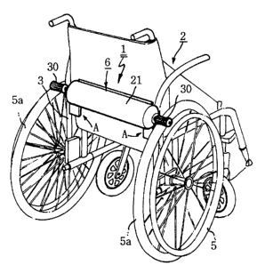
FIG. 1 is a perspective view of the rear surface of a wheelchair
in which the transmission of the present invention is employed
FIG. 2 is a schematic top view of the transmission unit as a
main part of the transmission of the present invention:
FIG. 3 is a rear view of the transmission of the present
invention employed in the wheelchair;
FIG. 4 is an exploded perspective view of the clamping unit and
the switching unit as main parts of the transmission of the present
invention
FIG. 5 is a side view of the operational state of the switching
unit as the main part of the transmission of the present invention
FIG. 6 is a sectional view of the operational state of the
switching unit as the main part of the transmission of the present
invention
FIG. 7 is an enlarged sectional view of the operational state of
the switching unit as the main part of the transmission of the present
invention:
FIG. 8 is an enlarged perspective view showing another
embodiment of the clamping unit of the present invention
FIG. 9 is an exploded perspective view of FIG. 8.
FIG. 10 is an exploded perspective view of the clamping unit
and the transmission unit of the present invention;
FIG. 11 is a top view showing the connection state of the
transmission of the present invention with the wheels of the
wheelchair, while being in a partly disconnected state
FIG. 12 is a side sectional view showing the separated state of
the transmission of the present invention from the wheels of the
wheelchair and
FIG. 13 is a side sectional view showing the motor-driven state
where the transmission of the present invention is engaged with the
wheels of the wheelchair.
CA 02368303 2001-09-19
WO 00/59440 PCT/KR00/00298
-4-
Best Mode for Carrvin~ out the Invention
The present invention will now be described with reference to
the illustrated embodiments.
FIG. 1 is a perspective view of the rear surface of a wheelchair
2 in which the transmission 1 for the wheelchair of the present
invention is employed, FIG. 2 is a schematic top view of the
transmission unit 6 as a main part of the transmission 1 of the
present invention, and FIG. 3 is a rear view of the transmission 1 of
the present invention employed iri the wheelchair 2.
Generally, the wheelchair 2 is provided with a wheel 5a on the
both sides thereof, respectively and a driving wheel 5 coupled to the
outside of the wheel 5a for rolling the wheel 5a by the hand of a
user. The transmission for the wheelchair, according to the present
invention, is provided with the transmission unit 6 which is in a close
contact with the wheel 5a to rotatably drive the wheel 5a and is
coupled to a switching unit 'A' capable of selecting manual and
motor-driven ways.
As shown in FIG. 2, the construction according to a first
embodiment of the transmission unit 6 is as follows:
A motor 28, connected to a battery 31, is first installed in the
internal both sides of a casing 21, respectively and connected to an
accelerating and decelerating parts 29 on the both sides of the casing
21, respectively. A driving roller 30 is shaft-coupled to the both
accelerating and decelerating parts 20 on the outsides of the casing
21, respectively.
The motor 28 is connected to a motor control circuit unit 34
circuit-connected to the battery 31 and a controller 'C', and the
controller 'C' is mounted on a predetermined position of the
wheelchair 2, for supplying and stopping the power of the motor 28,
thereby rotating forwardly and reversely the motor 28 for the direction
control of the wheelchair 2.
In order for the driving roller 30 to be in close contact with the
outer peripheral surface of the wheel 5a on the each side of the
wheelchair 2 and to thus rotate the wheel 5a by the close contact
force, it is preferably formed by a rubber material having an excellent
CA 02368303 2001-09-19
WO 00/59440 PCT/KR00/00298
_5_
friction force and taking a prominence and depression shape.
A clamping unit 4 of the first embodiment is installed on the
one side of the casing 21 of the transmission unit 6 and thus coupled
attachably and detachably to/from the switching unit 'A' which is
fixedly installed on a frame 3 of the wheelchair 2, for the use in the
manual and motor-driven ways. Now, an explanation of the
construction of the switching unit 'A', which is coupled with the
transmission unit 6 to cause the driving roller 30 to be contacted or
deviated with/from the wheel 5a of the wheelchair 2, will be
discussed.
As shown in FIG. 4, the switching unit 'A' is . provided with a
fixing part 36 with an assembling reentrant hole 35 which is fixed on
the frame 3 of the each side of the wheelchair 2. The fixing part 36
forms a locking hole 37, and a fixing clip 38, which is assembled by
1.5 means of the clamping unit 4 with the casing 21 of the transmission
unit 6, is inserted into the fixing part 36. At this time, a locking
projection 40 on the fixing clip is locked and unlocked to/from the
locking hole 37 to thereby permit the driving roller 30 of the each side
of the transmission unit 6 to be contacted or deviated with/from the
wheel 5a of the wheelchair 2, such that the wheelchair 2 can move in
the manual and motor-driven ways. Next, a detailed explanation of the
construction of the switching unit 'A' will be given.
The fixing part 36 with the locking hole 37 on the both sides
thereof, respectively is fixedly assembled to the frame 3 of the
wheelchair 2. The casing 21 of the transmission unit 6 is coupled to
the fixing clip 38 by means of the clamping unit 4. The locking
projection 40 of the fixing clip 38 is inserted into the assembling
reentrant hole 35 of the fixing part 36 by means of a handle 39,
thereby being locked and unlocked to/from the locking hole 37.
As mentioned above, the fixing clip 38 coupled to the casing 21
of the transmission unit 6 is inserted into the assembling reentrant
hole 35 of the fixing part 36. In more detail, the fixing clip 38 is
elastically coupled to a spring 42 at the bottom side of a locker 41 to
which the locking projection 40 on the bottom surface of the inside of
the locker 41 is sliding-coupled at the side thereof, as shown in FIG.
CA 02368303 2001-09-19
WO 00/59440 PCT/KR00/00298
and is elastically coupled to a spring 43 on the top portion thereof,
as shown in FIG. 6, such that the locking projection 40 of each side
of the locker 41 are locked to the locking hole 37 of the fixing part
36.
5 The locking projections 40 of the both sides of the locker 41
are connected to a pulling string 44 which is connected to the handle
39, and between the locking projections 40, a return spring 25 is
elastically provided.
On the other hand, the handle 39 on the top side of the fixing
clip 38 is installed in such a fashion that it can be angle-moveable to
the straight top portions of the casing 21 of the transmission unit 6
and the fixing clip 38> centering around a shaft pin 46. A rotary unit
47 of the handle 39 is composed of a ratchet 48 and a guide roller
49, the ratchet 48 being locked to one side thereof by means of a
stopper 48a and the guide roller 49 being connected to a pulling
string 30 which is connected to the top portion of the locker 41.
On the end of the handle 39 a push button 51 is provided to
selectively contact and release the driving rollers 30 of the both sides
of the transmission unit 6 to/from the wheels 5a.
In other words, the push button 51 is assembled to be
elastically supported outwardly on the end of the handle 39 by means
of an inside spring 52. The one end of the push button 51 coupled to
the spring 52 is coupled by means of a link 53 to the one end of a
rotary plate 55 assembled to a shaft pin 54, and if the push button
51 is pressed, the other end of the rotary plate 55 on the axis of the
shaft pin 54 is angle-moved to the push button 51. The pulling
strings 44 and 50, each connected to the stopper 48a and the locking
projection 40 of the locker 41, are connected to the other end of the
rotary plate 55.
On the other hand, upon pushing the push button 51, a fixing
pin 57 is elastically assembled to a fixing groove 56 on the inside of
the handle 39. The fixing pin 57 is adapted to fix the pushing state
upon the pushing by the push button 51.
D
Of course, the stopper 48a, the pulling strings 44 and 50, the
CA 02368303 2001-09-19
WO 00/59440 PCT/KR00/00298
-7-
ratchet 48 and the stopper 48a may be employed by using various
other equivalent means.
In order for the clamping unit 4 which is adapted to assemble
the casing 21 of the transmission unit 6 and the switching unit 'A' to
-5 be installed irrespective of the type or size (width) of the wheelchair
2, it can be sliding-adjusted and set left and right to be matched with
the size of the wheelchair 2 and then fixed by means of a locking
screw 58. The driving rollers 30 at the both ends of the transmission
unit 6 are adjusted to be moved and set left and right on the
transmission shafts of the accelerating and decelerating parts 29,
depending upon the interval between the both wheels 5a and then
fixedly installed by means of the locking screw 58.
FIGS. 8 and 9 show a second embodiment of the clamping unit
4 of the present invention.
In more detail, the clamping unit 4 is provided with a bracket 7
on which a coupling hole 8 and a guide hole 9 are formed on the
upper and lower portions thereof. A climbing operation pin 10 drawn
from the transmission unit 6 is fitting-inserted into the coupling hole 8
on the upper portion of the bracket 7, and a climbing guider 11
drawn from the transmission unit 6 is coupled on the guide hole 9 on
the lower portion of the bracket 7. Preferably, the coupling hole 8
forms a locker 8b elastically installed by means of a twist spring 8a to
thereby prevent the climbing operation pin 10 from being arbitrarily
deviated therefrom and angle-moved to thereby lock the header
portion of the climbing operation pin 10.
On the top and bottom portions of the bracket 7, respectively, a
coupling hole 12 is formed left and right and horizontally, through
which a left and right adjusting bar 13 with a female screw hole 13a
is screw-installed by means of an adjusting bolt 14 and a snap ring
15, such that the left and right interval adjustment of the left and right
adjusting bar 13 can be made depending upon the screw adjustment
of the adjusting bolt 14.
On the front sides of the left and right adjusting bar 13,
respectively, a shaft hole 13b is provided up and down, through which
an angle adjusting bar 16 with a shaft hole 16a is fixed by means of
CA 02368303 2001-09-19
WO 00/59440 PCT/KR00/00298
a shaft pin 17 and a snap ring 15, such that the angle adjustment of
the angle adjusting bar 16 can be made on the basis of the shaft pin
17. On the angle adjusting bar 16 is coupled a clamp 19 for clamping
the frame 3 of the wheelchair 2 in a screw-tightening manner through
a screw coupling hole 20 by means of a clamping bolt 18.
The transmission unit 6 connected to the clamping unit 4 and
the switching unit 'A' for selecting the manual and motor-driven ways
can be of course employed in various other embodiments. FIGS. 10
and 11 show a second embodiment of the transmission unit 6 and the
switching unit 'A' of the present invention.
In more detail, a climbing motor 22 is installed i.n the casing 21,
and a worm gear 23 is shaft-fixed on a driving shaft 22a of the
climbing motor 22. A worm gear 24, which is gear-engaged with the
worm gear 23 in a right angle direction, is shaft-fixed on the center
of a driven shaft 25, thereby being driven in the interconnected
relationship with the worm gear 23. A pinion 26 is shaft-fixed on the
both ends of the driven shaft 25, respectively, with which a rack gear
27 is gear-engaged, and the climbing operation pin 10 as mentioned
above is fixedly formed on the opposite to the side on which the gear
teeth of the rack gear 27 is formed.
The motor 28 is installed on the left and right sides of the
interior of the casing 21, respectively and is coupled to the
accelerating and decelerating part 29 having an output shaft on which
the driving roller 30 is shaft-fixed, such that the driving roller 30 is
selectively contacted with the wheel 5a of the wheelchair 2 for driving
the wheel 5a.
The controller 'C' is separately provided to selectively drive the
forward and reverse directions of the climbing motor 22 and the motor
28 and also to selectively accelerate and decelerate the rotation speed
thereof. The controller 'C' can be used by any one of various kinds of
well-known controllers.
The transmission of the present invention configured in various
construction ways can drive and adjust the wheelchair 2 in a simple
manner, such that there is an advantage that it is greatly convenient
to work the transmission of the present invention. Now, an explanation
CA 02368303 2001-09-19
WO 00/59440 PCT/KR00/00298
_9_
of the use method of the present invention and the operation of each
component will be in detail discussed.
The casing 21 of the transmission unit 6 is coupled to the
fixing clip 38 by means of the clamping unit 4, and the fixing clip 38
is coupled to the assembling reentrant hole 35 of the fixing part 36
fixed on the frame 3 of the wheelchair 2. As a consequence, the
transmission unit 6 is fixedly installed on the wheelchair 2 by means
of the switching unit 'A', and the controller 'C' of the transmission unit
6 is disposed on the position where the user can be used in a
convenient manner.
Under the installation of the transmission unit. 6 as discussed
above, if the motor 28 is controlled by means of the controller 'C' in
the state where the driving roller 30 is installed to be in close contact
with the wheel 5a, the driving roller 30 rotates depending upon the
1.5 forward and reverse rotation directions of the motor 28, as shown in
FIG. 2, thereby moving the wheelchair 2.
The driving roller 30 of the transmission unit 6 is controlled by
means of the handle 39 on the top portion of the fixing clip 38, thus
to be closely contacted and separated with/from the wheel 5a, such
that the wheelchair 2 is selectively driven in the manual and
motor-driven ways. Hereinafter, an explanation of the switching unit
°A' will be disclosed.
If the push button 51 presses, it is pushed and inserted in the
inside of the switching unit 'A' and angle-moves the rotary plate 55,
thereby operating the locker 41 and the stopper 48a each connected
to the pulling strings 44 and 50.
If the stopper 48a pulls by means of the pulling string 50 by
the pressing of the push button 51, the stopper 48a which has fixed
the ratchet 48 of the rotary unit 47 of the handle 39 is released, such
that the handle 39 lifts upward centering around the shaft pin 46. At
the same time, while the pulling string 44 of the locker 41 pulls, the
locking projection 40 each locked to the locking holes 37 of the fixing
part 36 pulls in the inside thereof to be deviated from the locking hole
37, such that the locker 41 can lift upward.
If the handle 39 lifts upward in the state where the push button
CA 02368303 2001-09-19
WO 00/59440 PCT/KR00/00298
-10-
51 has pressed, the pulling string 44, which is connected to the
locker 41 and pulls the locking projection 44 in the inside thereof,
pulls to thereby lift the locker 41 upward in the state where the
locking projection 40 has been released to the locker 41. As a
consequence, the locking projection 40, which has been released from
the locking hole 37, is disposed in the inside of the fixing part 36.
Therefore, if the fixing clip 38 on which the locking projection
40 is released lifts to the upper portion of the fixing part 36, the
whole casing 21 of the transmission unit 6 assembled with the fixing
clip 38 slightly lifts upward, thereby permitting the driving roller 30 to
be separated from the wheel 5a, such that the driving wheel 5 can
move by the hand of the user, that is, the switching to the manually
operated state is carried out.
If the switching to the motor-driven state is needed, the handle
39 is returned to its original position and accordingly the ratchet 48 is
unlocked from the stopper 48a and returned to its original position.
Thereby, the pulling string 44 of the locker 41 is returned and thus
the locker 41 descends. As the locker 41 descends, if the locking
projection 40 reaches the position of the locking hole 37 of the fixing
part 36, it elastically protrudes outward and is fixedly locked to the
locking hole 37 by the recovery force of the return spring 45
elastically formed between the both locking projections 40. Thereby,
the casing 21 of the transmission unit 6 is fixed downward and the
driving roller 30 is in close contact with the wheel 5a, such that the
wheelchair 2 can be driven and moved under the control of the
controller 'C' by the manipulation of the user.
On the other hand, an explanation of the operation according to
the second embodiment of each of the clamping unit 4, the
transmission unit 6 and the switching unit 'A' of the present invention
will be in detail discussed.
In case of employing the clamping unit 4 as shown in FIGS. 8
and 9, in order to fix the clamping unit 4 on the frame 3 of the
wheelchair 2, the clamping bolt 18 is first screw-separated to place
the both clamps 19 on the top of the frame 3. Then, if the clamping
bolt 18 is screw-tightened, the clamping unit 4 can be fixed on the
CA 02368303 2001-09-19
WO 00/59440 PCT/KR00/00298
-11-
frame 3. In the case where the left and right climbing operation pin
and the climbing guider 11 of the transmission unit 6 which are
mounted on the clamping unit 4 have different left and right intervals,
if the adjusting bolt 14 screw-coupled on the left and right adjusting
5 bar 13 is screw-adjusted forwardly or reversely, the left and right
adjusting bar 13 is sliding-adjusted left and right by a predetermined
width to thereby set an appropriate left and right interval from the
transmission unit 6. In the same manner as above, in case of the
angle thereof, the angle adjusting bar 16 is angle-adjusted centering
10 around the shaft pin 17.
In order to assemble the transmission unit 6 with the clamping
unit 4, the climbing operation pin 10 and the climbing guider 11 of
the transmission unit 6 are each assembled on the coupling hole 8
and the guide hole 9 of the clamping unit 4. In more detail, if the
climbing operation pin 10 pushes and is then inserted into the
coupling hole 8, the locker 8b elastically installed by the twist spring
8a is installed on the left and right of the coupling hole 8, such that
the locker 8b opens in an angle-moved manner to the outer
peripheral surface of the coupling hole 8 by the insertion of the
climbing operation pin 10 and when the header portion of the climbing
operation pin 10 is passed through the coupling hole 8, the locker 8b
locks the rear side of the climbing operation pin 10 by the elastically
recovering force of the twist spring 8a to thereby prevent the deviation
of the climbing operation pin 10. On the other hand, the climbing
guider 11 advances to the guide hole 9 and serves to a guider upon
ascending up and down on the guide hole 9.
Upon completion of the assembly of the transmission unit 6
with the clamping unit 4, the disabled person is seated in the
wheelchair 2 and drives the wheelchair 2 in the motor-driven way by
the manipulation of the controller 'C' or rolls the driving wheel 5 in the
manually operated way. In this case, since the manual driving method
is well known, an explanation of which will be avoided for the brevity
of the description. At this time, the driving roller 30 of the
transmission unit 6 of the present invention is separated apart from
the wheel 5a.
CA 02368303 2001-09-19
WO 00/59440 PCT/KR00/00298
-12-
That is to say, the state as shown in FIG. 11 means the state
where the worm gear 24 on the driven shaft 25 is driven by the
rotation of the worm gear 23 connected on the driving shaft 22a by
the operation of the climbing motor 22 and the pinion 26 is then
raised from the rack gear 27 gear-engaged therewith by the rotation
thereof. If the pinion 26 rises, since the clamping unit 4 is fixed on
the frame 3 and the clamping unit 4 and the rack gear 27 are fixed
through the climbing operation pin 10 and the coupling hole 8, the
casing 21 of the transmission uriit 6 ascends together with the pinion
26. As a consequence, the driving roller 30 shaft-fixed on the casing
21 is isolated from the wheel 5a and the driving wheel 5 is driven in
the manually operated manner, for the driving of the wheelchair 2.
FIG. 12 shows the case where the wheelchair 2 is driven by the
operation of the transmission unit 6. At this time, the climbing motor
22 is driven in a reverse direction to as mentioned above and the
worm gear 24 on the driven shaft 25 is driven by the rotation of the
worm gear 23 connected on the driving shaft 22a. Thereby, the pinion
26 is rotated reversely and descends from the rack gear 27
gear-engaged therewith. If the pinion 26 descends, the casing 21 of
the transmission unit 6 descends together with the pinion 26. As a
consequence, the driving roller 30 shaft-fixed on the casing 21 is
contact-engaged with the wheel 5a, and the motor 28 and the
accelerating and decelerating part 29 are controlled and operated by
the control of the controller 'C', thereby driving the driving roller 30.
As a result, the driving rollers 30, which are engaged with the left and
right wheels 5a, are driven in a constant rotation or at accelerating or
decelerating rotation speed. Thus, if the wheelchair 2 is to be driven
in a forward, left and right rotation, or reverse direction, it can be
driven by the operation of the transmission unit 6.
Industrial Applicability
As set forth in the foregoing, the transmission for the wheelchair
according to the present invention can give the following advantages:
a) owing to its simple construction and convenient use method, it can
provide the wheelchair all used in the manual and motor-driven ways.
CA 02368303 2001-09-19
WO 00/59440 PCT/KR00/00298
-13-
b) because of the compactness and light weight of a transmission
unit, the overall weight of the wheelchair does not increase any more,
such that a convenient use in the manual way can be ensured: c)
because of the installation of left and right interval and angle adjusting
means and a clamping unit easily fixed on a frame, the compatibility
for various wheelchair sizes is provided; and d) since the transmission
unit and the switching unit are assembled and dissembled to/from the
clamping unit in a simple manner and ascend or descend to thereby
isolate or engage the driving roller from/with the wheel, the reliability
of operation is improved and owing to the simple construction, a
relatively low production cost is determined.
It will be apparent to those skilled in the art that various
modifications and variations can be made in a transmission for a
wheelchair of the present invention without departing from the spirit or
scope of the invention. Thus, it is intended that the present invention
cover the modifications and variations of this invention provided they
come within the scope of the appended claims and their equivalents.
25
35