Note: Descriptions are shown in the official language in which they were submitted.
CA 02368327 2001-09-14
LOW-DISPERSION OPTICAL FIBER AND OPTICAL TRANSMISSION
SYSTEM USING THE LOW-DISPERSION OPTICAL FIBER
TECHNICAL FIELD
This invention relates to a low-dispersion optical fiber
used for example when wavelength division multiplexing optical
transmission is carried out in the 1.5~Zm band, and to an optical
transmission system using this low-dispersion optical fiber.
BACKGROUND ART
With the development of the information society the amount
of information communicated has been increasing dramatically,
and the realization of high bit-rate and high capacities in
optical fiber communications has become an urgent and
unavoidable issue. As an approach to this realization of more
high bit-rate and capacities, optical fiber type optical
amplifiers, which by using an optical fiber doped with a rare
earth element, such as an erbium-doped optical fiber (EDF) doped
with Er3', can amplify an optical signal in the form of light,
have been developed. And with the development the optical
amplifiers which uses those optical fiber , the realization of
high-power signal light has been progressing rapidly.
Meanwhile, to increase communication capacities in
optical communications, communications using wavelength
division multiplexing optical transmission, wherein optical
signals having different wavelengths are transmitted down a
single optical fiber, have been being developed. And from the
1_
CA 02368327 2001-09-14
application of the optical amplifier which uses above-mentioned
optical fiber to optical communication using this wavelength
division multiplexing optical transmission (wavelength
multiplexing optical transmission systems), further increases
in communication capacity and the realization of long-distance
transmission are anticipated.
One representative example of an optical fiber type
optical amplifier is the EDFA (Erbium-Doped optical Fiber
Amplifier), which has an EDF of the kind mentioned above. The
use of the EDFA to conduct the above-mentioned wavelength
division multiplexing optical transmission with the l.5um
wavelength band (wavelength 1520nm to 1620nm) , which is the gain
band of the EDFA, as the transmission band has been being studied.
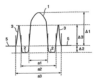
Figs. 6(a) and 6(b) show examples of refractive index
profiles of optical fibers that have been proposed in related
art as optical fibers for wavelength division multiplexing
optical transmission with, of the above-mentioned l.5um
wavelength band, particularly the 1550nm vicinity wavelength
band (the 1. 55um wavelength band) as the transmission band (used
wavelength band) . Fig. 6 (a) shows a dual shaped refractive index
profile, and Fig. 6 (b) shows a W-shaped refractive index profile.
The optical fiber with the dual shaped refractive index
profile is made up of a cladding 5, a center core 1 having a larger
refractive index than that of the cladding 5, and a first side
core 2 having a refractive index smaller than that of the center
core 1 but larger than that of the cladding 5. The optical fiber
2
CA 02368327 2001-09-14
with the W-shaped refractive index profile is made up of a
cladding 5, a center core 1 having a larger refractive index than
that of the cladding 5, and a first side core 2 having a refractive
index smaller than that of the cladding 5.
Among optical fibers with the dual shaped refractive index
profile described above, those having their zero dispersion
wavelength in the 1.55um wavelength vicinity are called
dispersion-shifted optical fibers. Because a dispersion-
shifted optical fiber has its zero dispersion wavelength in the
vicinity of the wavelength 1. 55pm, which is the center wavelength
of the 1.55um wavelength band, distortion of the signal light
waveform caused by dispersion in the 1.55um wavelength band is
suppressed. On the down side, however, the occurrence of the
nonlinear phenomenon of four-wave mixing is marked.
Consequently, with this dispersion-shifted optical fiber,
four-wave mixing light arising causes distortion to occur in the
waveform of the signal light, and it is impossible to realize
high-quality wavelength division multiplexing optical
transmission.
To overcome this, dual shaped refractive index profile
optical fibers having their zero dispersion wavelength shifted
from the 1.55um wavelength band have been developed. However,
it is known that in this kind of optical fiber the dispersion
gradient in the 1.55um wavelength band is large. And because
of that, with this kind of optical fiber it is difficult to make
small the chromatic dispersion differential in the used
3
CA 02368327 2001-09-14
wavelength band in wavelength division multiplexing optical
transmission (the difference between the maximum value and the
minimum value of the chromatic dispersion in the used wavelength
band). Consequently, when this kind of optical fiber is used,
it is not possible for the used wavelength band used for
wavelength division multiplexing opticaltransmission to be made
wide.
An optical fiber having the W-shaped refractive index
profile functions as a dispersion flattened optical fiber,
because the above-mentioned chromatic dispersion differential
is small. However, whereas the effective core area (the region
through which light effectively propagates: Aeff) of the dual
shaped refractive index profile optical fiber is about 45um',
the effective core area of a W-shaped refractive index profile
optical fiber is for example about 30umz, or about 2/3 of that
of the dual shaped refractive index profile optical fiber. And
when the effective core area is small like this, in wavelength
division multiplexing optical transmission there has been the
problem that the transmitted signal deteriorates as a result of
nonlinear phenomena arising in the optical fiber.
To overcome this, the idea of increasing the effective core
area by using an optical fiber having a segment core refractive
index profile of the kind shown in Fig. 6 (c) has been proposed.
In Fig. 6(c), 1 denotes a center core; 2 a first side core; 3
a second side core; and 5 a cladding. However, with this kind
of optical fiber, because the chromatic dispersion gradient in
4
CA 02368327 2001-09-14
the l.5um wavelength band is large and the chromatic dispersion
differential in the same wavelength band is large, when the
optical fiber of this proposal is applied to wavelength division
multiplexing transmission, the problem arises that signal light
waveform deterioration caused by chromatic dispersion becomes
marked.
Also, to apply an optical fiber to a wavelength division
multiplexing transmission system, the optical fiber must be
incorporated into a cable. And because the cable is required
to have the property that loss increases caused by bending of
the optical fiber and side pressures on the optical fiber are
low, it is also required of an optical fiber for wavelength
division multiplexing transmission use that its bending property
be good.
However, as explained above, there has not yet been
realized an optical fiber with which it is possible to obtain
both the effective core area and the reduced chromatic dispersion
differential necessary to realize a high-quality wavelength
division multiplexing transmission system, and additionally it
has been difficult to realize an optical fiber whose bending loss
property are also good.
Also, in recent years, as optical amplifiers, the Raman
amplifier has been approaching practical introduction. The
IW rnurr arr~pli..ficr_ his a wider amplifiable wavelength bend thn~n
existing EDFAs, and can amplify a light signal of any specified
wavelength band within for example the wavelength range of 1950nm
CA 02368327 2001-09-14
to 1650nm. However, studies of optical fibers in this wavelength
range have not yet advanced.
DISCLOSURE OF THE INVENTION
It is therefore an object of the present invention to
provide a low-dispersion optical fiber with which it is possible
to obtain both increased effective core area and reduced
chromatic dispersion differential in a used wavelength band and
furthermore to reduce loss increases caused by bending and side
pressures when the optical fiber is made into a cable, and an
optical transmission system using this low-dispersion optical
fiber.
A low-dispersion optical fiber of a first construction
provided by the invention to achieve this and other obj ects is
a dispersion-shifted optical fiber made by covering a center core
with a first side core, covering the first side core with a second
side core, and covering the second side core with a cladding,
characterized in that when the maximum refractive index of the
center core is written nl, the minimum refractive index of the
first side core is written n2, the maximum refractive index of
the second side core is written n3 and the refractive index of
the cladding is written nc, then nl>n3>nc>n2; the relative
refractive index difference O1 with respect to the cladding of
the maximum refractive index of the center core is 0. 9 o<_Ol<_0. 7 o;
the relative refractive index difference D2 with respect to the
cladding of the minimum refractive index of the first side core
is -0.300__<42<_-0.05%; the relative refractive index difference
6
CA 02368327 2001-09-14
D3 with respect to the cladding of the maximum refractive index
of the second side core is 0.20<_03; the ratio (al/a2) of the
diameter al of the center core to the diameter a2 of the first
side core is at least 0.4 and not greater than 0.7; and the ratio
(a3/a2) of the diameter a3 of the second side core to the diameter
a2 of the first side core is not greater than 1.6.
A low-dispersion optical fiber of a second construction
provided by the invention is characterized in that, in addition
to the first construction described above, the second side core
is doped with an additive which raises the refractive index of
Si02; the concentration distribution in the optical fiber radial
direction of the additive doped into the second side core has
a peak; and the position of the peak is on the first side core
side of the radial direction center of the second side core.
A low-dispersion optical fiber of a third construction
provided by the invention is characterized in that, in addition
to the second construction described above, the additive is GeO~.
A low-dispersion optical fiber of a fourth construction
provided by the invention is characterized in that, in addition
to the first or the second or the third construction described
above, a low refractive index cladding part of a smaller
refractive index than the cladding is provided between the
cladding and the second side core.
A low-dispersion optical fiber of a fifth construction
provided by the invention is characterized in that, in addition
to the first or the second or the third construction described
7
CA 02368327 2001-09-14
above, it does not have zero dispersion wavelength in a used
wavelength band included in the 1450nm to 1650nm wavelength band.
A low-dispersion optical fiber of a sixth construction
provided by the invention is characterized in that, in addition
to the fourth construction described above, it does not have zero
dispersion wavelength in a used wavelength band included in the
1450nm to 1650nm wavelength band.
A low-dispersion optical fiber of a seventh construction
provided by the invention is characterized in that, in addition
to the first or the second or the third or the sixth construction
described above, the differential between the maximum value and
the minimum value of the dispersion value in a wavelength band
having an arbitrary bandwidth of 30nm included in the wavelength
band 1450nm to 1650nm is not greater than 2 ps/nm/km.
A low-dispersion optical fiber of an eighth construction
provided by the invention is characterized in that, in addition
to the fourth construction described above, the differential
between the maximum value and the minimum value of the dispersion
value in a wavelength band having an arbitrary bandwidth of 30nm
included in the wavelength band 1450nm to 1650nm is not greater
than 2 ps/nm/km.
A low-dispersion optical fiber of a ninth construction
provided by the invention is characterized in that, in addition
to the fifth construction described above, the differential
between the maximum value and the minimum value of the dispersion
value in a wavelength band having a bandwidth of 30nm included
8
CA 02368327 2001-09-14
in the wavelength band 1450nm to 1650nm is not greater than 2
ps/nm/km.
An optical transmission system of a tenth construction
provided by the invention is characterized in that it has an
optical transmission line including a low-dispersion optical
fiber of any one of the first through ninth constructions
described above and a dispersion-compensating device whose
chromatic dispersion gradient in the wavelength band 1450nm to
1650nm is negative, and a positive chromatic dispersion gradient
of the optical transmission line in this wavelength band is
reduced by the dispersion-compensating device.
In this specification, the specific refractive indexes 01,
42 and 03 mentioned above are defined by the following expressions
( 1 ) through ( 3 ) .
O1 = { (nl2-ncz) /2nc2} x 100 . . . (1)
02 = { (n22-ncz) /2ncz} x 100 . . . (2)
D3 = { (n32-nc2) /2nc2} x 100 . . . (3)
A low-dispersion optical fiber according to the invention
has a first object of providing in a set wavelength band for
example within the wavelength range of 1450nm to 1650nm both an
increased effective core area and a reduced chromatic dispersion
differential in the used wavelength band. A low-dispersion
optical fiber according to the invention has its refractive index
distribution and its core diameter ratios optimized so that it
is possible to achieve this first object and also to reduce loss
increases caused by bending and side pressures when the optical
9
CA 02368327 2001-09-14
fiber is made into a cable. Thus, with a low-dispersion optical
fiber according to the invention, it is possible to obtain both
an increased effective core area and a reduced chromatic
dispersion differential in the used wavelength band and
furthermore to reduce loss increases caused by bending and side
pressures when the optical fiber is made into a cable. Specific
examples of low-dispersion optical fibers according to the
invention will be discussed hereinafter in the section on modes
of practicing the invention.
In one construction of a low-dispersion optical fiber
according to the invention, the second side core is doped with
an additive which raises the refractive index of Si02; the
concentration distributioninthe opticalfiber radial direction
of the additive doped into the second side core has a peak; and
the position of the peak is on the first side core side of the
radial direction center of the second side core. And in another
construction, a low refractive index cladding part of a smaller
refractive index than the cladding is provided between the
cladding and the second side core.
In these constructions, effective cutoff wavelength can
be made short. Consequently, with these constructions, it is
possible to achieve a still greater increase in effective core
area and a still greater reduction in the chromatic dispersion
differential in the used wavelength band, and a superior
low-dispersion optical fiber capable of single mode operation
can be obtained.
CA 02368327 2001-09-14
Also, in a construction wherein, as described above, a peak
in the concentration distribution in the optical fiber radial
direction of an additive doped into the second side core which
raises the refractive index of Si02 is positioned on the first
side core side of the radial direction center of the second side
core, if the additive is made Ge02, the optical fiber can be made
easily using existing optical fiber manufacturing technology.
And if a low-dispersion optical fiber according to the
invention is given a construction such that it does not have zero
dispersion wavelength in a used wavelength band within the
wavelength range of 1450nm to 1650nm, for example in the
wavelength band 1530nm to 1560nm, if for example wavelength
division multiplexing optical transmission is carried out in
this wavelength band, the occurrence of four-wave mixing can be
suppressed and waveform distortions caused by nonlinear
phenomena can consequently be suppressed. The above-mentioned
used wavelength band can be set freely within the wavelength range
of 1450nm to 1650nm.
And if in a low-dispersion optical fiber according to the
invention the differential between the maximum value and the
minimum value of the dispersion value in the above-mentioned
wavelength band is made 2 ps/nm/km or below, when for example
wavelength division multiplexing optical transmission is
carried out in this wavelength band, wave form distortions caused
by chromatic dispersion can be certainly suppressed.
An optical transmission system according to the invention
11
CA 02368327 2001-09-14
uses an optical transmission line including a low-dispersion
optical fiber described above and furthermore the positive
chromatic dispersion gradient in the wavelength band 1450nm to
1650nm of this optical transmission line including a low-
dispersion optical fiber is reduced by means of a negative
chromatic dispersion gradient of a dispersion-compensating
device. With an optical transmission system according the
invention, because the chromatic dispersion gradient in the
above-mentioned wavelength band can be made to approach zero and
the influence of chromatic dispersion can be suppressed still
more, it is possible to build an optical transmission system
capable of high-quality wavelength division multiplexing
transmission.
BRIEF DESCRIPTION OF THE DRAWINGS
Fig. 1 is a detail construction view showing the refractive
index distribution in the radial direction (refractive index
distribution over a cross-section) of a first embodiment of a
low-dispersion optical fiber according to the invention;
Fig. 2(a) is a detail construction view showing the
refractive index distribution in the radial direction of a second
embodiment of a low-dispersion optical fiber according to the
invention, and Fig. 2(b) is an explanatory view showing the
refractive index distribution in the radial direction of an
optical fiber made for comparison;
Fig. 3 is a detail construction view showing the refractive
index distribution in the radial direction of a third embodiment
12
CA 02368327 2001-09-14
of a low-dispersion optical fiber according to the invention;
Fig. 4 is a graph showing the dispersion characteristic
of an embodiment of an optical transmission system using a
low-dispersion opticalfiber according to the invention together
with the dispersion property of the low-dispersion optical fiber
applied to this optical transmission system;
Fig. 5(a) is an explanatory view showing the refractive
index distribution and Fig. 5 (b) a graph showing the dispersion
characteristic of a dispersion-compensating device applied to
the above-mentioned embodiment of an optical transmission
system; and
Figs. 6 (a) through 6 (c) are explanatory views showing the
refractive index distributions (refractive index distributions
over a cross-section) in the radial direction of optical fibers
proposed for wavelength division multiplexing optical
transmission use in related art.
BEST MODE FOR CARRYING OUT THE INVENTION
To explain the invention in more detail, a number of
embodiments of the invention will now be described on the basis
of the accompanying drawings. In the following explanation of
the embodiments, parts of the same name as parts in the related
art examples have been given the same reference numerals, and
duplicate descriptions are omitted. Fig. 1 shows the refractive
index profile (refractive index distribution structure) of a
first embodiment of a low-dispersion optical fiber according to
the invention.
13
CA 02368327 2001-09-14
As shown in the figure, this low-dispersion optical fiber
has a center core 1 covered by a first side core 2; the first
side core 2 is covered with a second side core 3; and the second
side core 3 is covered with a cladding 5. Also, in this
low-dispersion optical fiber, when the maximum refractive index
of the center core 1 is written nl, the minimum refractive index
of the first side core 2 is written n2, the maximum refractive
index of the second side core 3 is written n3 and the refractive
index of the cladding 5 is written nc, then nl>n3>nc>n2.
The most characterizing feature of this first embodiment
of the invention is that the relative refractive index difference
D3 with respect to the cladding 5 of the maximum refractive index
of the second side core 3 is made at least 0. 2 o and the maximum
value n3 of the refractive index of the second side core 3 is
made much larger than the refractive index nc of the cladding
5. And, in this first embodiment, the relative refractive index
difference Dl with respect to the cladding 5 of the maximum
refractive index of the center core 1 is made at least 0. 4 o and
not greater than 0. 7 0 (0. 4%<_O1<_0. 7 0) , and the relative refractive
index difference D2 with respect to the cladding 5 of the minimum
refractive index of the first side core 2 is made at least -
0.300 and not greater than -0.050 (-0.300<_~2<_-0.050).
In this first embodiment, preferably, the relative
refractive index difference O1 with respect to the cladding 5
of the maximum refractive index of the center core 1 is made at
least 0. 42 o and not greater than 0 . 62 0 (0. 42 oS~l<_0. 62 0 ) , and the
14
CA 02368327 2001-09-14
relative refractive index difference D2 with respect to the
cladding 5 of the minimum refractive index of the first side core
2 is made at least -0.250 and not greater than -0.050 (-
0.250<_02<_-0.050).
And in this first embodiment, preferably, the ratio
(al/a2) of the diameter al of the center core 1 to the diameter
a2 of the first side core 2 is made at least 0.4 and not greater
than 0.7, and the ratio (a3/a2) of the diameter a3 of the second
side core 3 to the diameter a2 of the first side core 2 is made
not greater than 1.6. More preferably, the ratio (a3/a2) of the
diameter a3 of the second side core 3 to the diameter a2 of the
first side core 2 is not greater than 1.5.
In the low-dispersion optical fiber of this first
embodiment, the constitution of the optical fiber is not
particularly limited. An optical fiber having the refractive
index profile described above can be made by for example doping
a center core 1 and a second side core 3 with Ge02 and doping
a first side core 2 with F. The additive doped into the second
side core 3 is not limited to Ge02, and may be some other additive
which raises the refractive index of Si02, for example A1z03 or
the like.
In the example shown in Fig. 1, the concentration
distribution in the optical fiber radial direction of the GeO
doped into the center core 1 has a peak in the center of the center
core 1. And the concentration distribution in the optical fiber
radial direction of the Ge02 doped into the second side core 3
x
y
CA 02368327 2001-09-14
also has a peak, in the radial direction center of the second
side core 3. The optical fiber may alternatively have a peak
in the concentration distribution of the Ge02 in the optical fiber
radial direction other than in the center of the center core 1.
In this first embodiment, by the refractive index profile
and the ratios of the core diameters of the center core 1, the
first side core 2 and the second side core 3 being specified as
described above, it is possible to obtain both an increased
effective core area and a reduced chromatic dispersion
differential in the used wavelength band. And, with the
low-dispersion optical fiber of this first embodiment, losses
caused by bending in the used wavelength band are small and it
is possible to obtain good property when the optical fiber is
incorporated into a cable.
In the low-dispersion optical fiber of this first
embodiment, specifically, the effective core area is made at
least 45~zmz, and the absolute value of the dispersion (units:
ps/nm/km) anywhere from wavelength 1530nm to wavelength 1560nm
is made at least 2 and not greater than 12 so that the optical
fiber does not have a zero dispersion wavelength in the used
wavelength band. Also, in the low-dispersion optical fiber of
this first embodiment, the dispersion gradient anywhere in the
used wavelength band is made not greater than 0.05 ps/nmz/km and
the difference between the maximum value and the minimum value
of the dispersion in the used wavelength band (the dispersion
differential) is made not greater than 2 ps/nm/km.
16
CA 02368327 2001-09-14
In specifying the refractive index profile and core
diameter ratios set forth above, the present inventors obtained
the property of various optical fibers by performing trials and
simulations. As a result, it was found that when the above-
mentioned relative refractive index difference O1 is less than
0. 4 0, although it is possible to realize increased effective core
area and reduced chromatic dispersion gradient, bending losses
of the optical fiber tend to increase and it is difficult to
maintain good property when the optical fiber is made into a
cable.
On the other hand it was found that when the relative
refractive index difference D1 exceeds 0.70, the chromatic
dispersion gradient becomes large; the chromatic dispersion
differential becomes larger than in an optical fiber with the
dual shaped refractive index profile described above; and the
effective core area becomes approximately the same as that of
a dual shaped refractive index profile optical fiber. For these
reasons, as set forth above, in this first embodiment of the
invention, the relative refractive index difference D1 was made
from 0. 4 o to 0 . 7 0 .
Although the relative refractive index difference 01 can
be set anywhere within the above range, when the refractive index
profile of the center core 1 is an a-power profile, preferably
the relative refractive index difference dl is made somewhat
small when a is large and is made somewhat large when a is small.
The refractive index profile being an a-power profile means that
17
CA 02368327 2001-09-14
the refractive index has the shape of a curve y=-xa centered on
the center of the core. As a typical example, when a is 4 to
6, the relative refractive index difference O1 is preferably made
0.53% to 0.600.
When the relative refractive index difference D2 is made
less than -0.300, although the chromatic dispersion gradient
becomes small, the effective core area also becomes small. And
when the relative refractive index difference 02 is made larger
than -0.05%, although the effective core area becomes large, the
chromatic dispersion gradient becomes approximately as large as
in a dual shaped refractive index profile optical fiber of related
art. For these reasons, as set forth above, in this first
embodiment of the invention, the relative refractive index
difference ~2 was made -0.300<_025-0.050.
Also, in an optical fiber with the refractive index profile
described above, as the ratio (al/a2) of the diameter al of the
center core 1 to the diameter a2 of the first side core 2 becomes
smaller, there is the tendency that it becomes more difficult
to obtain low bending loss in the 1450nm to 1650nm wavelength
band. And there is the tendency that effective cutoff wavelength
becomes long and single mode operation of the optical fiber
becomes difficult. And when the above-mentioned ratio (al/a2)
is less than 0.4, bending loss increase in the 1450nm to 1650nm
wavelength band becomes marked and the optical fiber is not
suitable for use in a cable.
When on the other hand the above-mentioned ratio (al/a2)
18
CA 02368327 2001-09-14
is larger than 0.7, obtaining a low chromatic dispersion value
becomes difficult, and the optical fiber becomes unsuitable for
wavelength division multiplexing optical transmission in the
1450nm to 1650nm wavelength band. For these reasons, in this
first embodiment of the invention, as set forth above, the
above-mentioned ratio (al/a2) is made at least 0. 4 but not greater
than 0.7.
And when the diameter of the second side core 3 is large
and the ratio (a3/a2) of the diameter a3 of the second side core
3 to the diameter a2 of the first side core 2 exceeds 1.6,
effective cutoff wavelength becomes long and single mode
operation of the optical fiber becomes difficult. For this
reason, in this first embodiment of the invention, this ratio
(a3/a2) is made not greater than 1.6.
In this first embodiment, the refractive index profile and
the core diameter ratios were specified on the basis of the
studies described above. Consequently, both an increased
effective core area and a reduced chromatic dispersion
differential in the used wavelength band are obtained; the
occurrence of four-wave mixing is suppressed; losses caused by
bending in the used wavelength band are small; and good property
can be obtained when the optical fiber is made into a cable.
In Table 1, as specific examples of this first embodiment
of the invention, the relative refractive index differences 01,
~2 and D3, the core diameter ratios al/a2 and a2/a3 and the core
diameter a3 in each of a number of examples 1 through 9 are shown
19
CA 02368327 2001-09-14
together with the property of each example. And the property
of examples far comparison are shown in Table 2.
CA 02368327 2001-09-14
ble 1)
T
a 'r '~r"'w c~rrm ~rm
(
ao 0oaiQi--~o~~o~ cti
uf7 O ~ O r-t17r ~ O
C~ CVCO07iCMCV~ O O
N
tijt~D~ ~ tii~ O
u~
U
N
O ~ ~ O O O O
O O O G7O O GOp
.
,.,
~DN N CON ~1O
'~t N njCVCM~ ~f)tf~d'
T1
U
M O fjCOc0!L7r-tn~ ,
L O
00 H 0.7n.1~:00Is
ti O o ciO o O o 0
~ N ~ ~ ~ m
c~c~
O O
O O O O
(~ri
a- m ~ ~ c~W c'~~ m
, i o 0 o io0 0 0
o
c
In l) InO N O O O
t - - GVGV
N o O ~- r-~-~ ~
~
d C? C?~ O C~O C~O O
O O h~-h 1ns!'M O 00
C
1.~ ~ 'd~ll~tl~O l(~~
1 O
O O O O O O O O
.-., ~ m . c~~ ~ co
.~:
' W W
W W j W W W
WW
21
CA 02368327 2001-09-14
(Table2)
chromaticdispersioneffecfinebending
~1 e2 a1/a2dispersiongi.adient core loss
area
Units 90 ~O psJnmlkmpslnmvkm ~c m2 dB/m
conpanisr
example0.55 -0.45 0.55 -0.8 0.009 37 8.1
1
conpanisr0 0.2 0.36 ~ 0.0845 45 I i.8
~ 8 , I 0.5 I I
~
example2, .
In Tables 1 and 2, the values of chromatic dispersion,
dispersion gradient, effective core area (Aeff) and bending loss
are all values at the wavelength 1550nm. And bending loss are
all values when bending of 20 mm in diameter was applied to the
optical fiber. And although it is not shown in Table 1, in the
optical fibers of all of the examples 1 through 9, effective
cutoff wavelength is on the short wavelength side of the used
wavelength band in the wavelength range 1450nm to 1650nm, and
single mode operation is possible.
In particular, in examples 8 and 9, the bending loss is
below 1dB/m, and not only loss increases caused by bending and
side pressures when the optical fiber is made into a cable but
also loss increases caused by minute bends can be reduced.
In Table 2, comparison example 1 is a W-shaped refractive
22
CA 02368327 2001-09-14
index profile optical fiber of the kind shown in Fig. 6(b) and
comparison example 2 is a dual shaped refractive index profile
optical fiber of the kind shown in Fig. 6 (a) . In Table 2 also,
the relative refractive index difference Dl was obtained in the
same way as in the first embodiment described above and in the
case of comparison example 1 the relative refractive index
difference ~2 was also obtained in the same way as in the first
embodiment described above. In the case of comparison example
2, the relative refractive index difference D2 shows the relative
refractive index difference with respect to the cladding 5 of
the maximum refractive index of the first side core 2, and was
obtained using the foregoing expression (2) with the maximum
refractive index of the first side core 2 as n2 and the refractive
index of the cladding 5 as nc.
As is clear from a comparison of the property shown in
Tables 1 and 2, in all of examples 1 through 9 the effective core
area is larger than in comparison examples 1 and 2 and the
dispersion gradient is smaller than in comparison examples 1 and
2. Thus, by a comparison between examples 1 through 9 and
comparison examples 1 and 2 it was confirmed that this first
embodiment of the invention has good property. That is, with
this first embodiment of the invention, both an increased
effective core area and a reduced chromatic dispersion
differential in the used wavelength band are obtained, and also,
in the used wavelength band, the loss due to bending when bending
of 20 mm in diameter was applied to the optical fiber was small,
23
CA 02368327 2001-09-14
at under 20dB/m, so that good property are obtained when the
optical fiber is made into a cable.
Next, a second embodiment of a low-dispersion optical
fiber according to the invention will be described. The second
embodiment described here has the refractive index profile shown
in Fig. 2(a). In this low-dispersion optical fiber, the
refractive index peak where the refractive index of the second
side core 3 assumes its maximum value is on the first side core
2 side of the radial direction center of the second side core
3. Otherwise, the refractive index profile shown in Fig. 2(a)
is substantially the same as the refractive index profile shown
in Fig. 1. Preferably, the refractive index peak of the second
side core 3 is as close to the first side core 2 side as possible.
The refractive index profile shown in Fig. 2 (a) is achieved
by locating the position of the peak in the optical fiber radial
direction of the concentration distribution of GeOz serving as
an additive which raises the refractive index of Si02 doped into
the second side core 3 on the first side core 2 side of the radial
direction center of the second side core 3.
Because this second embodiment of the invention has this
refractive index profile, there is the effect that effective
cutoff wavelength is shortened and single mode operation of the
optical fiber is certainly possible over the whole of the used
wavelength band.
Az shown in Fig.2(b) with substamtially the same
construction as in the example 10, the construction and property
24
CA 02368327 2001-09-14
of an example 10 serving as a specific example of this second
embodiment are shown in Table 3. The construction and property
of a trial sample 1 wherein the concentration distribution of
Ge02 doped into the second side core 3 is made substantially
constant in the optical fiber radial direction are also shown
in Table 3.
(Table3)
chromatic effective
ei e2 e3 a11a2831x2dispersiondispersioneffecfinecutoff
gradientco,~e wevelength
area
Units a 30 9~ pslnmlkmslnm211cm~c m2
Example 0.525-0.150.35 0.5471.33 3.11 0.044 55 1516
trial sample0.525-0.150.35 0.5471.33 3.11 0.044 56 1
1
Also, as optical fibers having parameters different from
those of example 10, the present inventors constructed examples
11 and 12, wherein the position of the peak in the optical fiber
radial direction concentration distribution of Ge02 doped into
the second side core 3 is close to the first side core 2 side.
The constructions and property of these examples 11 and 12 are
shown in Table 4. In Table 4, the position of the peak in the
optical fiber radial direction concentration distribution of
Ge02 in the second side core 3 is expressed with the first side
CA 02368327 2001-09-14
core 2 side taken as 0 and the cladding 5 taken as 1.
Also shown in Table 4 are the constructions and property
of trial samples 2 and 3 having substantially the same parameters
as examples 11 and 12 but made with the position of the peak in
the optical fiber radial direction concentration distribution
of GeOZ doped into the second side core 3 closer to the cladding
side.
26
CA 02368327 2001-09-14
(Table4)
N
H
cd
M r Wit't-
N M M M
-
rH ~ 1'~T T !'."
O
_
W
~
O
N
U
- '
a~ N d 'c~d ~T
ftS
'
O
U
O
O O O
;b ~ COO O O
0oviO cn
x m tr~rM
riririai
H
O
a
N
Q.
O N ~ a0
o
p
~
fs.
0 0 0 0
4",
0
,~
G
O
O
U
R.
M ~
COM M M
T T T r
n r n n
O O O O
M M M M M
~
G ~ O O O O
N N N
N cV
o
r r r n
~I ~ O O O O
m
.~~
a
a~
,
GjW
27
CA 02368327 2001-09-14
As is clear from these tables, effective cutoff wavelength
differs greatly with differences in the concentration
distribution of Ge02 doped into the second side core 3.
Here, in the examples in Table 4, changes in property of
when bending losses are made about 1dB/m are shown, and there
is a tendency for example for the chromatic dispersion and the
dispersion gradient to increase slightly when the refractive
index peak of the second side core 3 is moved to the first side
core 2 side of the radial direction center of the second side
core 3. However, it is possible to adjust the chromatic
dispersion and the dispersion gradient value by a method other
than moving the refractive index peak of the second side core
3. For example, the refractive index of the center core 1 or
the first side core 2 can be changed.
Preferably, the effect of adjusting the dispersion value
and the dispersion gradient is obtained by moving the position
of the refractive index peak of the second side core 3 into the
1/3 of the width of the second side core 3 on the first side core
2 side. This is also preferable from the points of view of
manufacturability and manufacturing dispersion.
The present inventors found that when the relative
refractive index differences Ol, 02 and 03, the ratio (al/a2)
of the diameter al of the center core 1 to the diameter a2 of
the first side core 2 and the ratio (a3/a2) of the diameter a3
of the second side core 3 to the diameter a2 of the first side
28
CA 02368327 2001-09-14
core 2 are set within the specified range shown in the description
of Fig. 1 to make the effective core area much larger and to reduce
the chromatic dispersion differential in the used wavelength
band, depending on the set values (for example as in trial sample
1) it sometimes happens that effective cutoff wavelength becomes
long.
That is, generally, when a second side core 3 is provided
in an optical fiber to increase the effective core area Aeff, the
cutoff wavelength moves to the long wavelength side. And as for
example in the case of the trial sample 1 in Table 3 it may happen
that the optical fiber will not operate in the single mode in
a used wavelength band within the wavelength range 1450nm to
1650nm.
In this connection, the present inventors carried out
various studies into moving effective cutoff wavelength to the
short wavelength side to make single mode operation possible.
As a result it was discovered that when the refractive index
distribution of the second side core 3 is made the kind of
distribution shown for example in Fig. 2(a), as in example 10,
example 11 and example 12, it is possible to shorten effective
cutoff wavelength and realize increased effective core area and
reduced chromatic dispersion differential in the used wavelength
band to a much higher level.
That is, as in example 10, 'example 11 and example 12 shown
in Fig. 2 (a) and Table 3 and Table 4, the refractive index peak
of the second side core 3 is brought to the first side core 2
29
CA 02368327 2001-09-14
side of the radial direction center of the second side core 3.
This moves the cutoff wavelength to the short wavelength side
and makes it possible to obtain an optical fiber which can operate
in the single mode in a used wavelength band within the wavelength
range 1450nm to 1650nm.
The inventors consider the reason for this to be as follows .
Of the propagation modes of the optical fiber, the LPom
(m=2,3,...) and LP11 modes have an electric field distribution
in a wide range in the optical fiber radial direction.
Consequently, by moving the refractive index peak of the second
side core 3 to the first side core 2 side of the radial direction
center of the second side core 3 it is possible to prevent light
from propagating in the LPom mode and the LP11 mode while keeping
the influence on the LPoI mode of light propagating through the
optical fiber small, and thus make single mode operation
possible.
The construction of the first embodiment of the invention
was specified as described above on the basis of this study, and
provides the beneficial effects mentioned above as shown in Table
3 and Table 4.
A third embodiment of a low-dispersion optical fiber
according to the invention will now be described. This third
embodiment has the refractive index profile shown in Fig. 3.
This refractive index profile is substantially the same as that
shown in Fig. 1, except that a low refractive index cladding part
4 having a lower refractive index than the cladding 5 is provided
CA 02368327 2001-09-14
between the cladding 5 and the second side core 3.
The inventors carried out on a low-dispersion optical
fiber having this construction the same study as the study carried
out to specify the construction shown in Fig. 2(a). The
construction shown in Fig. 3 was specified on the basis of this
study, and by providing the low refractive index cladding part
4 it is possible to obtain the same effect as when the refractive
index peak at which the refractive index of the second side core
3 assumes its maximum value is moved to the first side core 2
side of the radial direction center of the second side core 3.
Table 5 shows the construction and property of an example
13 serving as a specific example of this embodiment having the
low refractive index cladding part 4 and the construction and
property of a trial sample 4 made with substantially the same
construction as the example 13 but without the low refractive
index cladding part 4. As is clear from this table, by providing
the low refractive index cladding part 4 between the cladding
and the second side core 3 it is possible to shorten effective
cutoff wavelength.
31
CA 02368327 2001-09-14
(Tables)
e ~Spersion~ ffe cuf
on afi ve dianeter
is ea
1 D2 D3 d4 alla2a31a2a4/a3p gradient toff
d si evelen
d t
g a3
% 90 % % ps/nmfkmnm~llCrn~c nm a m
m2
Example 0.425 -0.170.415-0.200.4751.35 1.80 4.82 0.046 64 1498 1.9
1 ~
t~ 0:425 -0.170.415 0.4751.35 5.251 0.022 67 2407 4.2
. sample4
32
CA 02368327 2001-09-14
Next, an embodiment of an optical transmission system
according to the invention will be described. This optical
transmission system has an optical transmission line including
at least one low-dispersion optical fiber according to one of
the embodiments described above and a dispersion-compensating
device whose chromatic dispersion gradient in the wavelength
band 1450nm to 1650nm is negative. And it is a characterizing
feature of this optical transmission system that the positive
chromatic dispersion gradient of the optical transmission line
including the low-dispersion optical fiber is reduced by means
of the dispersion-compensating device.
As an example, an optical transmission system was
constructed by connecting a low-dispersion optical fiber having
the construction and property of example 7 in Table 1 with a
dispersion-compensating device having negative dispersion and
a negative chromatic dispersion gradient.
A dispersion-compensating device for this application was
made using a dispersion-compensating optical fiber having the
kind of refractive index profile shown in Fig. 5(a). That is,
a dispersion-compensating device was made using a
dispersion-compensating optical fiber having a first side core
2 covering a center core 1, a second side core 3 covering the
first side core 2, and a cladding 5 covering the second side core
3.
In the dispersion-compensating optical fiber, if the
33
CA 02368327 2001-09-14
maximum refractive index of the center core 1 is written n1, the
minimum refractive index of the first side core 2 is written n2,
the maximum refractive index of the second side core 3 is written
n3 and the refractive index of the cladding 5 is written nc, then
nl>n3>nc>n2. And in this dispersion-compensating opticalfiber
the values of the relative refractive index differences O1, 42
and 03 are different from in the embodiments of low-dispersion
optical fibers according to the invention described above, with
~1 being about 2 . 85 0, D2 being about -1 o and ~3 being about 1 . 28 0 .
And the core diameter ratios (al/a2/a3) are approximately
1/3/3.7.
The dispersion property of the dispersion-compensating
device in the 1450nm to 1650nm wavelength band has a negative
dispersion (for example about -150 ps/nm/km or below at
wavelength 1550nm) and a negative chromatic dispersion gradient
(about -2.18 ps/nm2/km), and the absolute values of these are
both large. Accordingly, in the optical transmission system,
the ratio of the length of the low-dispersion optical fiber of
example 7 to the length of the dispersion-compensating device
was made 98 to 2.
In the 1530nm to 1600nm wavelength band, the optical
transmission system has the dispersion property shown by the
curve .~ in Fig. 4. Curve b in Fig. 4 shows the dispersion
characteristic in the 1530nm to 1600nm wavelength band of the
low-dispersion optical fiber of example 7.
As is clear from Fig. 4, when an optical transmission system
34
CA 02368327 2001-09-14
is built by connecting a dispersion-compensating device having
the kind of negative chromatic dispersion gradient shown in Fig.
5(b) to the low-dispersion optical fiber 7, the dispersion
differential in the used wavelength band (in this case a
wavelength band within the wavelength range 1450nm to 1650nm)
in the optical transmission system as a whole can be reduced much
further. And an example of a dispersion-compensating device
applied in this embodiment of an optical transmission system
according to the invention is a device having a negative chromatic
dispersion gradient with a large absolute value as mentioned
above.
When this kind of dispersion-compensating device is
applied, as described above, the length of the device can be made
short. Therefore, the application of this kind of
dispersion-compensating device reduces the amount of influence
had on nonlinear property and the like other than the dispersion
property and makes it possible to construct an optical
transmission system having the good property of the low-
dispersion optical fibers of the foregoing embodiments and
capable of high-quality wavelength division multiplexing
transmission.
The present invention is not limited to the embodiments
described above, and various modes of practicing the invention
can be employed. For example, in an optical transmission system
according to the invention an optical transmission line
including a low-dispersion optical fiber of one of the foregoing
CA 02368327 2001-09-14
embodiments and a dispersion-compensating device having a
negative chromatic dispersion gradient in the used wavelength
band are combined to reduce the dispersion differential in the
used wavelength band. Therefore, in an embodiment of an optical
transmission system according to the invention, the optical
transmission line may be made by connecting to a low-dispersion
optical fiber of one of the foregoing embodiments another optical
fiber, for example an optical fiber capable of single mode
operation.
And the construction of the dispersion-compensating
device applied to the embodiment of the optical transmission line
is not particularly limited and can be set according to
convenience. However, when the dispersion-compensating device
is made using a dispersion-compensating optical fiber as
described above, the making of the device and its connection to
an optical transmission line including a low-dispersion optical
fiber can be carried out easily.
And, in the embodiments of low-dispersion optical fibers
described above, Ge02 was doped into the center core 1 and the
second side core 3 and F was doped into the first side core 2.
However, an embodiment of a low-dispersion optical fiber
according to the invention may alternatively be given a
refractive index profile of a kind shown in Fig. 1, Fig. 2 or
Fig. 3 by Ge02 and F being doped into the first side core 2 and
the doping amounts of these being adjusted. Also, the
composition of a low-dispersion optical fiber according to the
36
CA 02368327 2001-09-14
invention can be set variously.
Also, although in each of the foregoing embodiments the
low-dispersion optical fiber was constructed not to have zero
dispersion wavelength in the 1530nm to 1560nm wavelength band,
a low-dispersion optical fiber according to the invention may
be constructed not to have zero dispersion wavelength in any used
wavelength band included in the wavelength band 1450nm to 1650nm.
When a low-dispersion optical fiber according to the invention
is constructed like this, because the occurrence of four-wave
mixing when wavelength division multiplexing transmission is
carried out in the used wavelength band can be suppressed, it
is possible to obtain a low-dispersion optical fiber suited to
wavelength division multiplexing transmission over a wider
bandwidth.
INDUSTRIAL APPLICABILITY
As described above, a low-dispersion optical fiber
according to this invention and an optical transmission system
using such a low-dispersion optical fiber can provide both
increased effective core area and reduced chromatic dispersion
differential in a used wavelength band and are therefore
well-suited to wavelength division multiplexing transmission.
37