Note: Descriptions are shown in the official language in which they were submitted.
CA 02368453 2001-09-27
WO 00/63886 PCTIUSOO/09604
-1-
DESCRIPTION
USING GAIN-ADAPTIVE QUANTIZATION AND NON-UNIFORM SYMBOL LENGTHS FOR AUDIO
CODING
TECHNICAL FIELD
The present invention relates generally to encoding and decoding signals. The
present invention may be used advantageously for split-band encoding and
decoding
in which frequency-subband signals are separately coded. The present invention
is
particularly useful in perceptual audio coding systems.
BACKGROUND ART
There is a continuing interest to encode digital audio signals in a form that
imposes low information capacity requirements on transmission channels and
storage
media yet can convey the encoded audio signals with a high level of subjective
quality. Perceptual coding systems attempt to achieve these conflicting goals
by using
a process that encodes and quantizes the audio signals in a manner that uses
larger
spectral components within the audio signal to mask or render inaudible the
resultant
quantizing noise. Generally, it is advantageous to control the shape and
amplitude of
the quantizing noise spectrum so that it lies just below the psychoacoustic
masking
threshold of the signal to be encoded.
A perceptual encoding process may be performed by a so called split-band
encoder that applies a bank of analysis filters to the audio signal to obtain
subband
signals having bandwidths that are commensurate with the critical bands of the
human
auditory system, estimates the masking threshold of the audio signal by
applying a
perceptual model to the subband signals or to some other measure of audio
signal
spectral content, establishes quantization step sizes for quantizing the
subband signals
that are just small enough so that the resultant quantizing noise lies just
below the
estimated masking threshold of the audio signal, quantizes the subband signals
according to the established quantization step sizes, and assembles into an
encoded
signal a plurality of symbols that represent the quantized subband signals. A
complementary perceptual decoding process may be performed by a split-band
decoder that extracts the symbols from the encoded signal and recovers the
quantized
subband signals therefrom, obtains dequantized representations of the
quantized
CA 02368453 2008-10-20
73221-55
-2-
subband signals, and applies a bank of synthesis filters to the dequantized
representations to generate an audio signal that is, ideally, perceptually
indistinguishable from the original audio signal.
The coding processes in these coding systems often use a uniform length
symbol to represent the quantized signal elements or components in each
subband
signal, Unfortunately, the use of uniform length symbols imposes a higher
information capacity than is necessary. The required information capacity can
be
reduced by using non-uniform length symbols to represent the quantized
components
in each subband signal.
One technique for providing non-uniform length symbols is Huffman
encoding of quantized subband-signal component. Typically, Hu$'inan code
tables are
designed using "training signals" that have been selected to represent the
signals to be
encoded in actual applications. Huffrnan coding can provide very good coding
gain if
the average probability density function (PDF) of the training signals are
reasonably
close to the PDF of the actual signal to be encoded, and if the PDF is not
flat.
If the PDF of the actual signal to be encoded is not close to the average PDF
of the training signals, Huffman coding will not realize a coding gain but may
incur a
coding penalty, increasing the information capacity requirements of the
encoded
signal. This problem can be minimized by using multiple code books
corresponding
to different signal PDFs; however, additional storage space is required to
store the
code books and additional processing is required to encode the signal
according to
each code book and then pick the one that provides the best results.
There remains a need for a coding technique that can represent blocks of
quantized subband-signal components using non-uniform length symbols within
each
subband, that is not dependent upon any particular PDF of component values,
and can
be performed efficiently using minimal computational and memory resources.
DISCLOSURE OF INVENTION
It is an object of some embodiments to provide for the advantages that can
be realized by using non-uniform length symbols to represent quantized signal
components such as subband-signal components within a respective frequency
subband in a split-band coding system.
CA 02368453 2008-10-20
73221-55
-3-
Some embodiments achieve this object using a technique that does not
depend upon any particular PDF of component values to achieve good coding gain
and can be performed efficiently using minimal computational and memory
resources.
In some applications, coding systems may advantageously use features of the
present
invention in conjunction with other techniques like Hu$'inan coding.
According to the teachings of one aspect of the present invention, a method
for
encoding an input signal comprises receiving the input signal and generating a
subband-signal block of subband-signal components representing a frequency
subband of the input signal; comparing magnitudes of the components in the
subband-
signal block with a threshold, placing each component into one of two or more
classes
according to component magnitude, and obtaining a gain factor; applying the
gain
factor to the components placed into one of the classes to modify the
magnitudes of
some of the components in the subband-signal block; quantizing the components
in
the subband-signal block; and assembling into an encoded signal control
information
conveying classification of the components and non-uniform length symbols
representing the quantized subband-signal components.
According to the teachings of another aspect of the present invention, a
method for decoding an encoded signal comprises receiving the encoded signal
and
obtaining therefrom control information and non-uniform length symbols, and
obtaining from the non-uniform length symbols quantized subband-signal
components
representing a frequency subband of an input signal; dequantizing the subband-
signal
components to obtain subband-signal dequantized components; applying a gain
factor
to modify magnitudes of some of the dequantized components according to the
control information; and generating an output signal in response to the
subband-signal
dequantized components.
These methods may be embodied in a medium as a program of instructions
that can be executed by a device to carry out the present invention.
According to the teachings of another aspect of the present invention, an
apparatus for encoding an input signal comprises an analysis filter having an
input
that receives the input signal and having an output through which is provided
a
subband-signal block of subband-signal components representing a frequency
subband of the input signal; a subband-signal block analyzer coupled to the
analysis
filter that compares magnitudes of the components in the subband-signal block
with a
CA 02368453 2008-10-20
73221-55
-4-
threshold, places each component into one of two or more classes according to
component magnitude, and obtains a gain factor; a subband-signal component
processor coupled to the subband-signal block analyzer that applies the gain
factor to
the components placed into one of the classes to modify the magnitudes of some
of
the components in the subband-signal block; a first quantizer coupled to the
subband-
signal processor that quantizes the components in the subband-signal block
having
magnitudes modified according to the gain factor; and a formatter coupled to
the first
quantizer that assembles non-uniform length symbols representing the quantized
subband-signal components and control information conveying classification of
the
components into an encoded signal.
According to the teachings of yet another aspect of the present invention in
an
apparatus for decoding an encoded signal, the apparatus comprises a
deformatter that
receives the encoded signal and obtains therefrom control information and non-
uniform length symbols, and obtains from the non-uniform length symbols
quantized
subband-signal components; a first dequantizer coupled to the deformatter that
dequantizes some of the subband-signal components in the block according to
the
control information to obtain first dequantized components; a subband-signal
block
processor coupled to the first dequantizer that applies a gain factor to
modify
magnitudes of some of the first dequantized components in the subband-signal
block
according to the control information; and a synthesis filter having an input
coupled to
the subband-signal processor and having an output through which an output
signal is
provided.
According to the teachings of yet another aspect of the present invention, a
medium conveys (1) non-uniform length symbols representing quantized subband-
signal components, wherein the quantized subband-signal components correspond
to
elements of a subband-signal block representing a frequency subband of an
audio
signal; (2) control information indicating a classification of the quantized
subband-
signal components according to magnitudes of the corresponding subband-signal
block elements; and (3) an indication of a gain factor that pertains to
magnitudes of
the quantized subband-signal components according to the control information.
CA 02368453 2008-10-20
73221-55
- 4a -
According to another aspect of the present
invention, there is provided a method for decoding an
encoded signal comprising: receiving the encoded signal and
obtaining therefrom control information and non-uniform
length symbols, and obtaining from the non-uniform length
symbols quantized subband-signal components representing a
frequency subband of an input signal; dequantizing the
subband-signal components to obtain a subband-signal block
of dequantized components; applying a gain factor to modify
magnitudes of some of the dequantized components according
to the control information to obtain a modified subband-
signal block of dequantized components, wherein each
dequantized component in the modified subband-signal block
is in one of two or more classes according to the respective
dequantized component magnitude as compared to a threshold
and all dequantized components as modified by the gain
factor are in the same class; and generating an output
signal in response to the modified subband-signal block of
dequantized components.
According to still another aspect of the present
invention, there is provided an apparatus for decoding an
encoded signal comprising: a deformatter that receives the
encoded signal and obtains therefrom control information and
non-uniform length symbols, and obtains from the non-uniform
length symbols quantized subband-signal components; a first
dequantizer coupled to the deformatter that dequantizes some
of the subband-signal components in the block according to
the control information to obtain a subband-signal block of
first dequantized components; a subband-signal block
processor coupled to the first dequantizer that applies a
gain factor to modify magnitudes of some of the first
dequantized components in the subband-signal block according
to the control information to obtain a modified subband-
CA 02368453 2008-10-20
73221-55
- 4b -
signal block of dequantized components, wherein each
dequantized component in the modified subband-signal block
is in one of two or more classes according to the respective
dequantized component magnitude as compared to a threshold
and all dequantized components as modified by the gain
factor are in the same class; and a synthesis filter having
an input coupled to the subband-signal processor and having
an output through which an output signal is provided.
According to yet another aspect of the present
invention, there is provided a computer program product
readable by a device embodying a program of instructions for
execution by the device to perform a method for decoding an
encoded signal, the method comprising: receiving the
encoded signal and obtaining therefrom control information
and non-uniform length symbols, and obtaining from the non-
uniform length symbols quantized subband-signal components
representing a frequency subband of an input signal;
dequantizing the subband-signal components to obtain a
subband-signal block of dequantized components; applying a
gain factor to modify magnitudes of some of the dequantized
components according to the control information to obtain a
modified subband-signal block of dequantized components,
wherein each dequantized component in the modified subband-
signal block is in one of two or more classes according to
the respective dequantized component magnitude as compared
to a threshold and all dequantized components as modified by
the gain factor are in the same class; and generating an
output signal in response to the modified subband-signal
block of dequantized components.
The various features of the present invention and
its preferred embodiments may be better understood by
referring to the following discussion and the accompanying
CA 02368453 2008-10-20
73221-55
- 4c -
drawings in which like reference numerals refer to like
elements in the
CA 02368453 2001-09-27
WO 00/63886 PCT/US00/09604
-5-
several figures. The contents of the following discussion and the drawings are
set
forth as examples only and should not be understood to represent limitations
upon the
scope of the present invention.
BRIEF DESCRIPTION OF DRAWINGS
Fig. 1 is a block diagram of a split-band encoder incorporating gain-adaptive
quantization.
Fig. 2 is a block diagram of a split-band decoder incorporating gain-adaptive
dequantization.
Fig. 3 is a flowchart illustrating steps in a reiterative bit-allocation
process.
Figs. 4 and 5 are graphical illustrations of hypothetical blocks of subband
signal components and the effects of applying gain to the components.
Fig. 6 is a block diagram of cascaded gain stages for gain-adaptive
quantization.
Figs. 7 and 8 are graphical illustrations of quantization functions.
Figs. 9A through 9C illustrate how a split-interval quantization function can
be
implemented using a mapping transform.
Figs 10 through 12 are graphical illustrations of quantization functions.
Fig. 13 is a block diagram of an apparatus that may be used to carry out
various aspects of the present invention.
MODES FOR CARRYING OUT THE INVENTION
A. Coding System
The present invention is directed toward improving the efficiency of
representing quantized information such as audio information and finds
advantageous
application in coding systems that use split-band encoders and split-band
decoders.
Embodiments of a split-band encoder and a split-band decoder that incorporate
various aspects of the present invention are illustrated in Figs. 1 and 2,
respectively.
1. Encoder
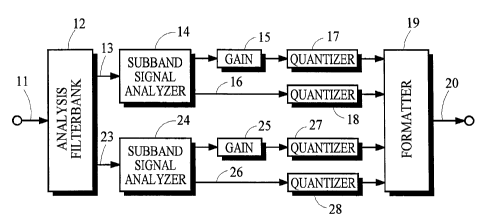
a) Analysis Filtering
In Fig. 1, analysis filterbank 12 receives an input signal from path 11,
splits
the input signal into subband signals representing frequency subbands of the
input
signal, and passes the subband signals along paths 13 and 23. For the sake of
CA 02368453 2001-09-27
WO 00/63886 PCT/USOO/09604
-6-
illustrative clarity, the embodiments shown in Figs. 1 and 2 illustrate
components for
only two subbands; however, it is common for a split-band encoder and decoder
in a
perceptual coding system to process many more subbands having bandwidths that
are
commensurate with the critical bandwidths of the human auditory system.
Analysis filterbank 12 may be implemented in a wide variety of ways
including polyphase filters, lattice filters, the quadrature mirror filter
(QMF), various
time-domain-to-frequency-domain block transforms including Fourier-series type
transforms, cosine-modulated filterbank transforms and wavelet transforms. In
preferred embodiments, the bank of filters is implemented by weighting or
modulating overlapped blocks of digital audio samples with an analysis window
function and applying a particular Modified Discrete Cosine Transform (MDCT)
to
the window-weighted blocks. This MDCT is referred to as a Time-Domain Aliasing
Cancellation (TDAC) transform and is disclosed in Princen, Johnson and
Bradley,
"Subband/Transform Coding Using Filter Bank Designs Based on Time Domain
Aliasing Cancellation," Proc. Int. Conf. Acoust., Speech, and Signal Proc.,
May 1987,
pp. 2161-2164. Although the choice of implementation may have a profound
effect on
the performance of a coding system, no particular implementation of the
analysis
filterbank is important in concept to the present invention.
The subband signals passed along paths 13 and 23 each comprise subband-
signal components that are arranged in blocks. In a preferred embodiment, each
subband-signal block is represented in a block-scaled form in which the
components
are scaled with respect to a scale factor. A block-floating-point (BFP) form
may be
used, for example.
If analysis filterbank 12 is implemented by a block transform, for example,
subband signals are generated by applying the transform to a block of input
signal
samples to generate a block of transform coefficients, and then grouping one
or more
adjacent transform coefficients to form the subband-signal blocks. If analysis
filterbank 12 is implemented by another type of digital filter such as a QMF,
for
example, subband signals are generated by applying the filter to a sequence of
input
signal samples to generate a sequence of subband-signal samples for each
frequency
subband and then grouping the subband-signal samples into blocks. The subband-
signal components for these two examples are transform coefficients and
subband-
signal samples, respectively.
CA 02368453 2008-10-20
73221-55
-7-
b) Perceptual Modeling
In a preferred embodiment for a perceptual coding system, the encoder uses a
perceptual model to establish a respective quantization step size for
quantizing each
subband signal. One method that uses a perceptual model to adaptively allocate
bits is
illustrated in Fig. 3. According to this method, step 51 applies a perceptual
model to
information representing characteristics of the input signal to establish a
desired
quantization-noise spectrum. In many embodiments, the noise levels in this
spectrum
correspond to the estimated psychoacoustic masking threshold of the input
signal.
Step 52 establishes initial proposed quantization step sizes for quantizing
the
components in the subband-signal blocks. Step 53 determines the allocations of
bits
that are required to obtain the proposed quantization step sizes for all
subband-signal
components. Preferably, allowance is made for the noise-spreading effects of
the
synthesis filterbank in the split-band decoder to be used to decode the
encoded signal.
Several methods for making such an allowance are disclosed in U.S. patent
5,623,577
and in U.S. patent 6,363,338 of Ubale, et al. entitled
"Quantization in Perceptual Audio Coders with Compensation for Synthesis
Filter
Noise Spreading" filed April 12, 1999.
Step 54 deterniines whether the total of the required allocations differs
significantly from the total number of bits that are available for
quantization. If the
total allocation is too high, step 55 increases the proposed quantization step
sizes. If
the total allocation is too low, step 55 decreases the proposed quantization
step sizes.
The process returns to step 53 and reiterates this process until step 54
determines that
the total allocation required to obtain the proposed quantization step sizes
is
sufficiently close to the total number of available bits. Subsequently, step
56 quantizes
the subband-signal components according to the established quantization step
sizes.
c) Gain-Adaptive Quantization
Gain-adaptive quantization may be incorporated into the method described
above by including various aspects of the present invention into step 53, for
example.
Although the method described above is typical of many perceptual coding
systems, it
is only one example of a coding process that can incorporate the present
invention.
The present invention may be used in coding systems that use essentially any
subjective and/or objective criteria to establish the step size for quantizing
signal
CA 02368453 2001-09-27
WO 00/63886 PCTIUSOO/09604
-8-
components. For ease of discussion, simplified embodiments are used herein to
explain various aspects of the present invention.
The subband-signal block for one frequency subband is passed along path 13
to subband-signal analyzer 14, which compares the magnitude of the subband-
signal
components in each block with a threshold and places each component into one
of
two classes according to component magnitude. Control information conveying
the
classification of the components is passed to formatter 19. In a preferred
embodiment,
the components that have a magnitude less than or equal to the threshold are
placed
into a first class. Subband-signal analyzer 14 also obtains a gain factor for
subsequent
use. As will be explained below, preferably the value of the gain factor is
related to
the level of the threshold in some manner. For example, the threshold may be
expressed as a function of only the gain factor. Alternatively, the threshold
may be
expressed as a function of the gain factor and other considerations.
Subband-signal components that are placed into the first class are passed to
gain element 15, which applies the gain factor obtained by subband-signal
analyzer 14
to each component in the first class, and the gain-modified components are
then
passed to quantizer 17. Quantizer 17 quantizes the gain-modified components
according to a first quantization step size and passes the resulting quantized
components to formatter 19. In a preferred embodiment, the first quantization
step
size is set according to a perceptual model and according to the value of the
threshold
used by subband-signal analyzer 14.
Subband-signal components that are not placed into the first class are passed
along path 16 to quantizer 18, which quantizes these components according to a
second quantization step size. The second quantization step size may be equal
to the
first quantization step size; however, in a preferred embodiment, the second
quantization step size is smaller than the first quantization step size.
The subband-signal block for the second frequency subband is passed along
path 23 and is processed by subband-signal analyzer 24, gain element 25, and
quantizers 27 and 28 in the same manner as that described above for the first
frequency subband. In a preferred embodiment, the threshold used for each
frequency
subband is adaptive and independent of the threshold used for other frequency
subbands.
CA 02368453 2001-09-27
WO 00/63886 PCT/US00/09604
-9-
d) Encoded Signal Formatting
Formatter 19 assembles the control information conveying the classification of
the components and non-uniform length symbols representing the quantized
subband-
signal components into an encoded signal and passes the encoded signal along
path 20
to be conveyed by transmission media including baseband or modulated
communication paths throughout the spectrum including from supersonic to
ultraviolet
frequencies, or by storage media including magnetic tape, magnetic disk and
optical
disc that convey information using a magnetic or optical recording technology.
The symbols used to represent the quantized components may be identical to
the quantized values or they may be some type of code derived from the
quantized
values. For example, the symbols may be obtained directly from a quantizer or
they
may be obtained by some process such as Huffman encoding the quantized values.
The quantized values themselves may be easily used as the non-uniform length
symbols because non-uniform numbers of bits can be allocated to the quantized
subband signal components in a subband.
2. Decoder
a) Encoded Signal Deformatting
In Fig. 2, deformatter 32 receives an encoded signal from path 31 and obtains
therefrom symbols that represent quantized subband-signal components and
control
information that conveys the classification of the components. Decoding
processes
can be applied as necessary to derive the quantized components from the
symbols. In
a preferred embodiment, gain-modified components are placed into a first
class.
Deformatter 32 also obtains any information that may be needed by any
perceptual
models or bit allocation processes, for example.
b) Gain-Adaptive Dequantization
Dequantizer 33 receives the components for one subband-signal block that are
placed in the first class, dequantizes them according to a first quantization
step size,
and passes the result to gain element 35. In a preferred embodiment, the first
quantization step size is set according to a perceptual model and according to
a
threshold that was used to classify the subband-signal components.
Gain element 35 applies a gain factor to the dequantized components received
from dequantizer 33, and passes the gain-modified components to merge 37. The
operation of gain element 35 reverses the gain modifications provided by gain
CA 02368453 2001-09-27
WO 00/63886 PCT/US00/09604
-10-
element 15 in the companion encoder. As explained above, preferably this gain
factor
is related to the threshold that was used to classify the subband-signal
components.
Subband-signal components that are not placed into the first class are passed
to dequantizer 34, which dequantizes these components according to a second
quantization step size, and passes the result to merge 37. The second
quantization step
size may be equal to the first quantization step size; however, in a preferred
embodiment, the second quantization step size is smaller than the first
quantization
step size.
Merge 37 forms a subband-signal block by merging the gain-modified
dequantized components received from gain element 35 with the dequantized
components received from dequantizer 36, and passes the resulting subband-
signal
block along path 38 to synthesis filterbank 39.
Quantized components in the subband-signal block for the second frequency
subband are processed by dequantizers 43 and 44, gain element 45 and merge 47
in
the same manner as that described above for the first frequency subband, and
passes
the resulting subband-signal block along path 48 to synthesis filterbank 39.
c) Synthesis Filtering
Synthesis filterbank 39 may be implemented in a wide variety of ways that are
complementary to the ways discussed above for implementing analysis filterbank
12.
An output signal is generated along path 40 in response to the blocks of
subband-
signal components received from paths 38 and 48.
B. Features
1. Subband-Signal Component Classification
a) Simplified Threshold Function
The effects of gain-adaptive quantization may be appreciated by referring to
Fig. 4, which illustrates hypothetical blocks 111, 112 and 113 of subband-
signal
components. In the example illustrated, each subband-signal block comprises
eight
components numbered from 1 to 8. Each component is represented by a vertical
line
and the magnitude of each component is represented by the height of the
respective
line. For example, component 1 in block 111 has a magnitude slightly larger
than the
value 0.25 as shown on the ordinate axis of the graph.
Line 102 represents a threshold at the 0.50 level. Each component in block
111 may be placed into one of two classes by comparing the respective
component
CA 02368453 2001-09-27
WO 00/63886 PCT/US00/09604
-11-
magnitudes with the threshold. The components having a magnitude less than or
equal
to the threshold are placed into a first class. The remaining components are
placed
into a second class. Alternatively, slightly different results may be obtained
if
components are classified by placing into the first class those components
that have a
magnitude strictly less than the threshold. For ease of discussion, threshold
comparisons made according to the first example will be assumed and mentioned
more particularly herein.
The components in block 112 are obtained by applying a gain factor of two to
each block 111 component that is placed into the first class. For example, the
magnitude of component 1 in block 112, which is slightly larger than 0.500, is
obtained by multiplying the magnitude of component 1 in block 111 with a gain
factor
equal to two. Conversely, the magnitude of component 2 in block 112 is equal
to the
magnitude of component 2 in block 111 because this component was placed into
the
second class and is not modified by the gain factor.
Line 104 represents a threshold at the 0.251evel. Each component in block
111 may be placed into one of two classes by comparing the respective
component
magnitudes with this threshold and placing the components having a magnitude
less
than or equal to the threshold into a first class. The remaining components
are placed
into a second class.
The components in block 113 are obtained by applying a gain factor of four to
each block 111 component that is placed into the first class. For example, the
magnitude of component 3 in block 113, which is about 0.44, is obtained by
multiplying the magnitude of component 3 in block 111, which is about 0.11,
with a
gain factor equal to four. Conversely, the magnitude of component 1 in block
113 is
equal to the magnitude of component 1 in block 111 because this component was
placed into the second class and is not modified by the gain factor.
The threshold may be expressed as a function of only the gain factor. As
shown by these two examples, the threshold may be expressed as
Th = ~ (1)
where Th = the threshold value; and
G = gain factor.
CA 02368453 2001-09-27
WO 00/63886 PCTIUSOO/09604
-12-
b) Alternative Threshold Function
Unfortunately, a threshold obtained from expression 1 may be too large
because a subband-signal component having a magnitude that is slightly less
than
threshold Th, when modified by gain factor G, may overload the quantizer.
A value is said to overload a quantizer if the quantization error of that
value
exceeds one-half the quantization step size. For symmetric quantizers having a
uniform quantization step size that quantize values into a range from
approximately -1
to +1, the region of positive quantities that overload the quantizer may be
expressed
as
QOL > QMax + A (2a)
and the region of negative values that overload the quantizer may be expressed
as
QOL < -Q,yax - ~Q (2b)
where QOL = a value that overloads the quantizer;
Qm,4x = maximum positive quantized value; and
AQ = quantization step size.
For a b-bit symmetric mid-tread signed quantizer having a uniform
quantization step size that quantizes values into a range from approximately -
1 to +1,
the maximum positive quantized value QmAx is equal to 1-21"b, the quantization
step
size AQ is equal to 21"b, and one-half the quantization step size is equal to
2"b.
Expression 2a for positive overload values may be rewritten as
QOL >1-21-b +2-b =I-2-b (3a)
and expression 2b for negative overload values may be rewritten as
QOL <-(1-21 b)-2 b =-1+2-b. (3a)
Line 100 in Fig. 4 represents the boundary of positive overload values for a
3-bit symmetric mid-tread signed quantizer. The negative range of this
quantizer is
not shown. The maximum positive quantized value for this quantizer is 0.75 =(1-
21"3)
and one-half the quantization step size is 0.125 = 2"3; therefore, the
boundary for the
positive overload values for this quantizer is 0.875 (1-2"3). The boundary for
negative overload values is -0.875.
CA 02368453 2001-09-27
WO 00/63886 PCT/US00/09604
- 13 -
Component 5 in block 111 has a magnitude that is slightly less than the
threshold at value 0.500. When a gain factor equal to two is applied to this
component, the resultant magnitude exceeds the overload boundary of the
quantizer.
A similar problem occurs for component 6 when a threshold equal to 0.250 is
used
with a gain factor equal to four.
A threshold value for positive quantities that avoids overload and optimally
maps the domain of positive component values in the first class into the
positive range
of a quantizer may be expressed as
Th = QGL (4a)
The threshold for the negative quantities may be expressed as
Th = - QGL . (4b)
Throughout the remainder of this discussion, only the positive threshold will
be discussed. This simplification does not lose any generality because those
operations that compare component magnitudes with a positive threshold are
equivalent to other operations that compare component amplitudes with positive
and
negative thresholds.
For the b-bit symmetric mid-tread signed quantizer described above, the
threshold function of expression 4a may be rewritten as
Th - 1 ~ -b (5)
The effects of gain-adaptive quantization using this alternative threshold are
illustrated in Fig. 5, which illustrates hypothetical blocks 121, 122, 123 and
124 of
subband signal components. In the examples illustrated, each subband-signal
block
comprises eight components numbered from 1 to 8, the magnitudes of which are
represented by the length of respective vertical lines. Lines 102 and 104
represent the
thresholds for a 3-bit symmetric mid-tread signed quantizer for gain factors
equal to 2
and 4, respectively. Line 100 represents the boundary of positive overload
values for
this quantizer.
The components in subband-signal block 122 may be obtained by comparing
the magnitudes of the components in block 121 with threshold 102 and applying
a
gain of G=2 to the components that have magnitudes less than or equal to the
CA 02368453 2001-09-27
WO 00/63886 PCT/US00/09604
-14-
threshold. Similarly, the components in subband-signal block 123 may be
obtained by
comparing the magnitudes of the components in block 121 with threshold 104 and
applying a gain of G=4 to the components that have magnitudes less than or
equal to
this threshold. The components in subband-signal block 124 may be obtained
using a
cascade technique, described below. Unlike the examples shown in Fig. 4 for
the first
threshold discussed above, none of the gain-modified components shown in Fig.
5
exceed the overload boundary of the quantizer.
On one hand, the alternative threshold according to expression 5 is desirable
because it avoids quantizer overload for small-magnitude components in the
first class
and optimally loads the quantizer. On the other hand, this threshold may not
be
desirable in some embodiments that seek an optimum quantization step size
because
the threshold cannot be determined until the quantization step size is
established. In
embodiments that adapt the quantization step size by allocating bits, the
quantization
step size cannot be established until the bit allocation b for a respective
subband-
signal block is known. This disadvantage is explained in more detail below.
2. Quantization
Preferably, the quantization step size of the quantizers used to quantize
components in a subband-signal block is adapted in response to the gain factor
for that
block. In one embodiment using a process similar to that discussed above and
illustrated in Fig. 3, a number of bits b is allocated to each component
within a
subband-signal block and then the quantization step size and possibly the bit
allocation is adapted for each component according to the gain factor selected
for that
block. For this embodiment, the gain factor is selected from four possible
values
representing gains of 1, 2, 4 and 8. Components within that block are
quantized using
a symmetric mid-tread signed quantizer.
Larger-magnitude components that are not placed into the first class and are
not gain modified are assigned the same b number of bits as would be allocated
without the benefit of the present invention. In an alternative embodiment
using a
split-interval quantization function discussed below, the bit allocation for
these larger-
magnitude components can be reduced for some gain factors.
Smaller-magnitude components that are placed into the first class and are gain
modified are allocated a number of bits according to the values shown in Table
I.
CA 02368453 2001-09-27
WO 00/63886 PCTIUSOO/09604
- 15-
Gain Allocation
1 b
2 b-i
4 b-2
8 b-3
Table I
A gain factor equal to I for a particular subband-signal block indicates the
gain-modified feature of the present invention is not applied to that block;
therefore,
the same b number of bits are allocated to each component as would be
allocated
without the benefit of the present invention. The use of gain factor G=2, 4
and 8 for a
particular subband-signal block can potentially provide the benefit of a
reduced
allocation of 1, 2 and 3 bits, respectively, for each smaller-magnitude
component in
that subband block.
The allocations shown in Table I are subject to the limitation that the number
of bits allocated to each component cannot be less than one. For example, if
the bit-
allocation process allocated b=3 bits to the components of a particular
subband-signal
block and a gain factor G=8 is selected for that block, the bit allocation for
the
smaller-magnitude components would be reduced to one bit rather than to zero
bits as
suggested by Table I. The intended effect of the gain modification and the
adjustment
to the bit allocation is to preserve essentially the same signal-to-
quantization-noise
ratio using fewer bits. If desired, an embodiment may avoid selecting any gain
factor
that does not reduce the number of allocated bits.
3. Control Information
As explained above, subband-signal analyzer 14 provides control information
to formatter 19 for assembly into the encoded signal. This control information
conveys the classification for each component in a subband-signal block. This
control
information may be included in the encoded signal in a variety of ways.
One way to include control information is to embed into the encoded signal a
string of bits for each subband-signal block in which one bit corresponds to
each
component in the block. A bit set to one value, the value 1 for example, would
indicate the corresponding component is not a gain modified component, and a
bit set
to the other value, which is the value 0 in this example, would indicate the
corresponding component is a gain modified component. Another way to include
CA 02368453 2001-09-27
WO 00/63886 PCT/US00/09604
-16-
control information is to embed a special "escape code" in the encoded signal
immediately preceding each component that is gain modified or, alternatively,
is not
gain modified.
In the preferred embodiment discussed above that uses a symmetric mid-tread
signed quantizer, each large-magnitude component that is not gain modified is
preceded by an escape code that is equal to an unused quantization value. For
example, the quantization values for a 3-bit two's complement signed quantizer
ranges
from a minimum of -0.750, represented by the 3-bit binary string b'l01, to a
maximum of +0.75, represented by the binary string b'O 11. The binary string
b' l00,
which corresponds to -1.000, is not used for quantization and is available for
use as
control information. Similarly, the unused binary string for a 4-bit two's
complement
signed quantizer is b' l 000.
Referring to subband-signal block 121 in Fig. 5, components 4 and 5 are large-
magnitude components that exceed threshold 102. If this threshold is used in
conjunction with a gain factor G=2, the bit allocation for all small-magnitude
components placed in the first class is b-1 as shown above in Table I. If the
bit-
allocation process allocates b=4 bits to each component in block 121, for
example, the
allocation for each subband-signal component would be reduced to 3=(b-1) bits
and a
3-bit quantizer would be used to quantize the small-magnitude components. Each
large-magnitude component, which in this example are components 4 and 5, would
be
quantized with a 4-bit quantizer and identified by control information that
equals the
unused binary string of the 3-bit quantizer, or b'100. This control
information for each
large-magnitude component can be conveniently assembled into the encoded
signal
immediately preceding the respective large-magnitude component.
It may be instructional to point out that the present invention does not
provide
any benefit in the example discussed in the preceding paragraph. The cost or
overhead
required to convey the control information, which is six bits in this example,
is equal
to the number of bits that are saved by reducing the bit allocation for the
small-
magnitude components. Referring to the example above, if only one component in
block 121 were a large-magnitude component, the present invention would reduce
the
number of bits required to convey this block by four. Seven bits would be
saved by
reduced allocations to seven small-magnitude components and only three bits
would
be required to convey the control information for the one large-magnitude
component.
CA 02368453 2001-09-27
WO 00/63886 PCT/USOO/09604
-17-
This last example ignores one additional aspect. Two bits are required for
each
subband-signal block in this exemplary embodiment to convey which of four gain
factors are used for that block. As mentioned above, a gain factor equal to 1
may be
used to indicate the features of the present invention are not applied for a
particular
subband-signal block.
The present invention usually does not provide any advantage for quantizing
subband-signal blocks with four or fewer components. In perceptual coding
systems
that generate subband signals having bandwidths commensurate with the critical
bandwidths of the human auditory system, the number of components in subband-
signal blocks for low-frequency subbands is low, perhaps only one component
per
block, but the number of components per subband-signal block increases with
increasing subband frequency. As a result, in preferred embodiments, the
processing
required to implement features of the present invention may be restricted to
the wider
subbands. An additional piece of control information may be embedded into the
encoded signal to indicate the lowest frequency subband in which gain-adaptive
quantization is used. The encoder can adaptively select this subband according
to
input signal characteristics. This technique avoids the need to provide
control
information for subbands that do not use gain-adaptive quantization.
4. Decoder Features
A decoder that incorporates features of the present invention may adaptively
change the quantization step size of its dequantizers in essentially any
manner. For
example, a decoder that is intended to decode an encoded signal generated by
encoder
embodiments discussed above may use adaptive bit allocation to set the
quantization
step size. The decoder may operate in a so called forward-adaptive system in
which
the bit allocations may be obtained directly from the encoded signal, it may
operate in
a so called backward-adaptive system in which the bit allocations are obtained
by
repeating the same allocation process that was used in the encoder, or it may
operate
in a hybrid of the two systems. The allocation values obtained in this manner
are
referred to as the "conventional" bit allocations.
The decoder obtains control information from the encoded signal to identify
gain factors and the classification of the components in each subband-signal
block.
Continuing the example discussed above, control information that conveys a
gain
factor G=1 indicates the gain-adaptive feature was not used and the
conventional bit
CA 02368453 2001-09-27
WO 00/63886 PCT/US00/09604
-18-
allocation b should be used to dequantize the components in that particular
subband-
signal block. For other gain factor values, the conventional bit allocation b
for a block
is used to determine the value of the "escape code" or control information
that
identifies the large-magnitude components. In the example given above, an
allocation
of b=4 with a gain factor G=2 indicates the control information is the binary
string
b' 100, which has a length equal to 3=(b-1) bits. The presence of this control
information in the encoded signal indicates a large-magnitude component
immediately follows.
The bit allocation for each gain-modified component is adjusted as discussed
above and shown in Table I. Dequantization is carried out using the
appropriate
quantization step size and the gain-modified components are subjected to a
gain factor
that is the reciprocal of the gain factor used to carry out gain modification
in the
encoder. For example, if small-magnitude components were multiplied by a gain
factor G=2 in the encoder, the decoder applies a reciprocal gain G=0.5 to the
corresponding dequantized components.
C. Additional Features
In addition to the variations discussed above, several alternatives are
discussed
below.
1. Additional Classifications
According to one alternative, the magnitudes of the components in a subband-
signal block are compared to two or more thresholds and placed into more than
two
classes. Referring to Fig. 5, for example, the magnitude of each component in
block
121 could be compared to thresholds 102 and 104 and placed into one of three
classes.
Gain factors could be obtained for two of the classes and applied to the
appropriate
components. For example, a gain factor G=4 could be applied to the components
having magnitudes less than or equal to threshold 104 and a gain factor G=2
could be
applied to the components having a magnitude less than or equal to threshold
102 but
larger than threshold 104. Alternatively, a gain factor G=2 could be applied
to all of
the components having magnitudes less than or equal to threshold 102 and a
gain
factor G=2 could be applied again to the components that had magnitudes less
than or
equal to threshold 104.
CA 02368453 2001-09-27
WO 00/63886 PCTIUSOO/09604
-19-
2. Cascaded Operation
The gain modification process described above may be carried out multiple
times prior to quantization. Fig. 6 is a block diagram that illustrates one
embodiment
of two gain stages in cascade. In this embodiment, subband-signal analyzer 61
compares the magnitudes of the components in a subband-signal block with a
first
threshold and places the components into one of two classes. Gain element 62
applies
a first gain factor to the components placed into one of the classes. The
value of the
first gain factor is related to the value of the first threshold.
Subband-signal analyzer 64 compares the magnitudes of the gain-modified
components and possibly the remaining components in the block with a second
threshold and places the components into one of two classes. Gain element 65
applies
a second gain factor to the components placed into one of the classes. The
value of the
second gain factor is related to the value of the second threshold. If the
second
threshold is less than or equal to the first threshold, subband-signal
analyzer 64 does
not need to analyze the components that analyzer 61 placed into the class for
magnitudes greater than the first threshold.
The subband-signal block components are quantized by quantizers 67 and 68
in a manner similar to that discussed above.
Referring to Fig. 5, the components in subband-signal block 124 may be
obtained by the successive application of gain stages in which subband-signal
analyzer 61 and gain element 62 apply a gain factor G=2 to the components
having a
magnitude less than or equal to threshold 102, and subband-signal analyzer 64
and
gain element 65 apply a gain factor G=2 to the gain-modified components having
a
magnitude that is still less than or equal to threshold 102. For example,
components 1
to 3 and 6 to 8 in block 121 are modified by a gain factor G=2 in the first
stage, which
produces an interim result that is shown in block 122. Components 1, 3, 7 and
8 are
modified by a gain factor G=2 in the second stage to obtain the result shown
for block
124.
In embodiments that use gain stages in cascade, suitable control information
should be provided in the encoded signal so that the decoder can carry out a
complementary set of gain stages in cascade.
CA 02368453 2001-09-27
WO 00/63886 PCT/US00/09604
-20-
3. Optimized Bit Allocation
There are several possible strategies for applying gain-adaptive quantization.
One simple strategy analyzes the components in a respective subband-signal
block by
starting with a first threshold and related first gain factor G=2 and
determines if gain-
adaptive quantization according to the first threshold and first gain factor
yields a
reduction in the bit allocation requirements. If it does not, analysis stops
and gain-
adaptive quantization is not carried out. If it does yield a reduction,
analysis continues
with a second threshold and related second gain factor G=4. If the use of the
second
threshold and related gain factor does not yield a reduction in bit
allocation, gain
adaptive quantization is carried out using the first threshold and first gain
factor. If the
use of the second threshold and second gain factor does yield a reduction,
analysis
continues with a third threshold and related third gain factor G=8. This
process
continues until either the use of a threshold and related gain factor do not
yield a
reduction in bit allocation, or until all combinations of thresholds and
related gain
factors have been considered.
Another strategy seeks to optimize the choice of gain factor by calculating
the
cost and benefit provided by each possible threshold and related gain factor
and using
the threshold and gain factor that yield the greatest net benefit. For the
example
discussed above, the net benefit for a particular threshold and related gain
factor is the
gross benefit less the cost. The gross benefit is the number of bits that are
saved by
reducing the bit allocation for the small-magnitude components that are gain
modified. The cost is the number of bits that are required to convey the
control
information for the large-magnitude components that are not gain modified.
One way in which this preferred strategy may be implemented is shown in the
following program fragment. This program fragment is expressed in pseudo-code
using a syntax that includes some syntactical features of the C, FORTRAN and
BASIC programming languages. This program fragment and the other programs
shown herein are not intended to be source code segments that are suitable for
compilation but are provided to convey a few aspects of possible
implementations.
CA 02368453 2001-09-27
WO 00/63886 PCT/USOO/09604
-21-
Gain(X,N,b) {
Th2 =(1-2^(-b)) / gf[l]; //initialize threshold for gain factor G=2
Th4 = Th2 / 2; ... for gain factor G=4
Th8 = Th4 / 2; ... for gain factor G=8
n2 = n4 = n8 = 0; //initialize counters
for (k=1 to N){ //for each component k...
CompMag = Abs(X[k]); //get component magnitude
if (CompMag > Th2)
n2 = n2 + 1; //count components above Th2
else if (CompMag > Th4)
n4 = n4 + 1; //count comp between Th4 and Th2
else if (CompMag > Th8)
n8 = n8 + 1; //count comp between Th8 and Th4
}
n24 = n2 + n4; //no. of large components above Th4
n248 = n24 + n8; //no. of large components above Th8
benefit2 = Min(b-1, 1); //bits per small component saved by using G=2
benefit4 = Min(b- 1, 2); //bits per small component saved by using G=4
benefit8 = Min(b-1, 3); //bits per small component saved by using G=8
net[0] = 0; //net benefit for no gain modification
net[1] = (N-n2) * benefit2 - n2 *(b-benefit2); //net benefit for using G=2
net[2] =(N-n24) * benefit4 - n24 *(b-benefit4); //net benefit for using G=4
net[3] = (N-n248) * benefit8 - n248 *(b-benefit8); //net benefit for using G=8
j = IndexMax(net[j], j=0 to 3); //get index of maximum benefit
Gain = gf[j]; //get gain factor
}
The function Gain is provided with an array X of subband-signal block
components, the number N of components in the block, and the conventional bit
allocation b for the block of components. The first statement in the function
uses a
calculation according to expression 5, shown above, to initialize the variable
Th2 to
represent the threshold that is related to a gain factor G=2 that is obtained
from an
array gf. In this example, the gain factors gf[1], gf[2) and gf[3] are equal
to G=2, 4
and 8, respectively. The next statements initialize variables for the
thresholds that are
related to gain factors G=4 and 8. Next, counters are initialized to zero that
will be
used to determine the number of large-magnitude components in various classes.
The statements in the for-loop invoke function Abs to obtain the magnitude for
each subband-signal block component in the array X and then compare the
component
magnitude with the thresholds, starting with the highest threshold. If the
magnitude is
greater than threshold Th2, for example, the variable n2 is incremented by
one. When
the for-loop is finished, the variable n2 contains the number of components
that have
a magnitude greater than threshold Th2, the variable n4 contains the number of
CA 02368453 2001-09-27
WO 00/63886 PCT/USOO/09604
-22-
components that have a magnitude that is greater than threshold Th4 but less
than or
equal to threshold Th2, and the variable n8 contains the number of components
that
have a magnitude that is greater than threshold Th8 but less than or equal to
threshold
Th4.
The two statements immediately following the for-loop calculate the total
number of components that are above respective thresholds. The number in
variable
n24 represents the number of components that have a magnitude greater than
threshold Th4, and the number in variable n248 represents the number of
components
that have a magnitude greater than threshold Th8.
The next three statements calculate the benefit per small-magnitude
component for using each gain factor. This benefit may be as much as 1, 2 or 3
bits
per component as shown above in Table I, but the benefit is also limited to be
no more
than b-1 bits per component since the allocation to each component is limited
to a
minimum of one bit. For example, the number in variable benefit2 represents
the
number of bits per small-magnitude component that are saved by using a gain
factor
G=2. As shown in Table I, this benefit may be as much as one bit; however, the
benefit is also limited to be no greater than the conventional bit allocation
b minus
one. The calculation of this benefit is provided by using the function Min to
return the
minimum of the two values b-1 and 1.
Net benefits are then calculated and assigned to elements of array net. The
element net[0] represents the net benefit of not using gain-adaptive
quantization,
which is zero. The net benefit for using a gain factor G=2 is assigned to
net[1] by
multiplying the appropriate benefit per small-magnitude component benefit2 by
the
appropriate number of small-magnitude components (N-n2) and then subtracting
the
cost, which is the number of large-magnitude components n2 multiplied by the
length
of the unused quantizer value used for the control information. This length is
the bit-
length of the small-magnitude components, which may be obtained from the
conventional bit allocation b reduced by the bits saved per small-magnitude
component. For example, the bit-length of the small-magnitude components when
the
gain factor G=2 is the quantity (b-benefit2). Similar calculations are
performed to
assign the net benefit for using gain factors G=4 and 8 to variables net[2]
and net [3],
respectively.
CA 02368453 2001-09-27
WO 00/63886 PCT/US00/09604
-23-
The function IndexMax is invoked to obtain the array index j for the largest
net benefit in the array net. This index is used to obtain the appropriate
gain factor
from the gf array, which is returned by the function Gain.
4. Improved Efficiency Using the Simplified Threshold Function
It was mentioned above that various features of the present invention may be
incorporated into a perceptual bit allocation process such as that illustrated
in Fig. 3.
In particular, these features may be performed in step 53. Step 53 is
performed within
a loop that reiteratively determines a proposed bit allocation for quantizing
components in each subband-signal block to be encoded. Because of this, the
efficiency of the operations performed in step 53 are very important.
The process discussed above for function Gain, which determines the
optimum gain factor for each block, is relatively inefficient because it must
count the
number of subband-signal block components that are placed in various classes.
The
component counts must be calculated during each iteration because the
thresholds that
are obtained according to expression 5 cannot be calculated until the proposed
bit
allocation b for each iteration is known.
In contrast to the thresholds obtained according to expression 5, the
thresholds
obtained according to expression 1 are less accurate but can be calculated
before the
proposed bit allocation b is known. This allows the thresholds and the
component
counts to be calculated outside the reiteration. Referring to the method shown
in
Fig. 3, the thresholds Thl, Th2 and Th3, and the component counts n2, n24 and
n248
could be calculated in step 52, for example.
An alternative version of the function Gain discussed above, which may be
used in this embodiment, is shown in the following program fragment.
Gain2 (X, N ) {
benefit2 = Min(b-1, 1); //bits per small component saved by using G=2
benefit4 = Min(b-1, 2); //bits per small component saved by using G=4
benefit8 = Min(b-1, 3); //bits per small component saved by using G=8
net[0] = 0; //net benefit for no gain modification
net[1] = (N-n2) * benefit2 - n2 *(b-benefit2); //net benefit for using G=2
net[2] = (N-n24) * benefit4 - n24 * (b-benefit4); //net benefit for using G=4
net[3] = (N-n248) * benefit8 - n248 * (b-benefit8); //net benefit for using
G=8
j = IndexMax(net[j], j=0 to 3); //get index of maximum benefit
Gain = gfjj]; //get gain factor
1
CA 02368453 2001-09-27
WO 00/63886 PCT/US00/09604
-24-
The statements in function Gain2 are identical to the corresponding statements
in function Gain discussed above that calculate the net benefits for each gain
factor
and then select the optimum gain factor.
5. Quantization Functions
a) Split-Interval Functions
The quantization accuracy of large-magnitude components can be improved
by using a split-interval quantization function that quantizes input values
within two
non-contiguous intervals.
Line 105 in Fig. 7 is a graphical illustration of a function that represents
the
end-to-end effect of a 3-bit symmetric mid-tread signed quantizer and
complementary
dequantizer. Values along the x axis represent input values to the quantizer
and values
along the q(x) axis represent corresponding output values obtained from the
dequantizer. Lines 100 and 109 represent the boundaries of positive and
negative
overload values, respectively, for this quantizer. Lines 102 and 108 represent
the
positive and negative thresholds, respectively, for gain factor G=2 according
to
expression 1 and as shown in Fig. 4. Lines 104 and 107 represent the positive
and
negative thresholds, respectively, for gain factor G=4.
Referring to Fig. 1, if subband-signal analyzer 14 classifies subband-signal
block components according to threshold 102, then it is known that the
magnitudes of
the components provided to quantizer 18 are all greater than threshold 102. In
other
words, quantizer 18 would not be used to quantize any values that fall between
thresholds 108 and 102. This void represents an under utilization of the
quantizer.
This under utilization may be overcome by using a quantizer that implements
a split-interval quantization function. A variety of split-interval functions
are possible.
Fig. 8 is a graphical illustration of a function that represents the end-to-
end effect of
one split-interval 3-bit signed quantizer and a complementary dequantizer.
Line 101
represents the function for positive quantities and line 106 represents the
function for
negative quantities.
The function shown in Fig. 8 has eight quantization levels in contrast to the
function shown in Fig. 7, which has only seven quantization levels. The
additional
quantization level is obtained by using the level discussed above that, for a
mid-tread
quantization function, corresponds to -1.
CA 02368453 2001-09-27
WO 00/63886 PCT/US00/09604
-25-
b) Non-Overloading Quantizers
A 3-bit quantizer and complementary dequantizer that implement the function
illustrated in Fig. 8 is preferred for quantizing values within a split-
interval from -1.0
to about -0.5 and from about +0.5 to +1.0 because the quantizer cannot be
overloaded.
As explained above, a value overloads a quantizer if the quantization error of
that
value exceeds one-half the quantization step size. In the example shown in
Fig. 8,
dequantizer outputs are defined for values equal to -0.9375, -0.8125, -0.6875,
-0.5625,
+0.5625, +0.6875, +0.8125 and +0.9375, and the quantization step size is equal
to
0.125. The magnitude of the quantization error for all values within the split-
interval
mentioned above is no greater than 0.0625, which is equal to one-half the
quantization
step size. Such a quantizer is referred to herein as a "non-overloading
quantizer"
because it is immune to overload.
Non-overloading single- and split-interval quantizers for essentially any
quantization step size may be realized by implementing a quantization function
having quantizer outputs that are bounded by quantizer "decision points"
spaced
appropriately within the intervals of values to be quantized. Generally
speaking, the
decision points are spaced apart from one another by some distance d and the
decision
points that are closest to a respective end of an input-value interval are
spaced from
the respective end by the amount d. This spacing provides a quantizer that,
when used
with a complementary dequantizer, provides uniformly spaced quantized output
values separated from one another by a particular quantization step size and
having a
maximum quantization error that is equal to one-half this particular
quantization step
size.
c) Mapping Functions
A split-interval quantizer may be implemented in a variety of ways. No
particular implementation is critical. One implementation, shown in Fig. 9A,
comprises mapping transform 72 in cascade with quantizer 74. Mapping transform
72
receives input values from path 71, maps these input values into an
appropriate
interval, and passes the mapped values along path 73 to quantizer 74.
If quantizer 74 is an asymmetric mid-tread signed quantizer, then the mapping
function represented by lines 80 and 81 illustrated in Fig. 9B would be
suitable for
mapping function 72. According to this mapping function, values within the
interval
from -1.0 to -0.5 are mapped linearly into an interval from -1.0-'/zOQ to -
'/ZAQ,
CA 02368453 2001-09-27
WO 00/63886 PCT/US00/09604
-26-
where AQ is the quantization step size of quantizer 74, and values within the
interval
from +0.5 to +1.0 are mapped linearly into an interval from -'/20Q to +1.0-
'/20Q. In
this example, no large-magnitude component can have a value exactly equal to
either
-0.5 or +0.5 because components with these values are classified as small-
magnitude
components. Because of this, mapping transform 72 will not map any input value
to
-'hOQ exactly; however, it may map input values arbitrarily close to and on
either
side of -'/zOQ.
The effect of this mapping may be seen by referring to Figs. 9B and 9C.
Referring to Fig. 9B, it can be seen that mapping transform 72 maps input
points 82
and 84 to mapped points 86 and 88, respectively. Referring to Fig. 9C, which
illustrates a function representing the end-to-end effects of a 3-bit
asymmetric mid-
tread signed quantizer and complementary dequantizer, the mapped points 86 and
88
may be seen to lie on either side of quantizer decision point 87, which has
the value
-'/20Q.
A complementary split-interval dequantizer may be implemented by an
asymmetric mid-tread signed dequantizer that is complementary to quantizer 74
followed by a mapping transform that is the inverse of mapping transform 72.
d) Composite Functions
In an example discussed above, gain-adaptive quantization with a gain factor
G=2 is used to quantize components of a subband signal for which conventional
bit
allocation b is equal to three bits. As explained above in conjunction with
Table I, 3
bits are used to quantize the large-magnitude components bits and 2=(b-1) bits
are
used to quantize the small-magnitude gain-modified components. Preferably, a
quantizer that implements the quantization function of Fig. 8 is used to
quantize the
large-magnitude components.
A 2-bit symmetric mid-tread signed quantizer and complementary dequantizer
that implement function 111 shown in Fig. 10 may be used for the small-
magnitude
gain-modified components. Function 111 as illustrated takes into account the
scaling
and descaling effects of the gain factor G=2 used in conjunction with the
quantizer
and dequantizer, respectively. The output values for the dequantizer are -
0.3333...,
0.0 and +0.3333..., and the quantizer decision points are at -0.1666 ... and
+0.1666
CA 02368453 2008-10-20
73221-55
-27-
A composite of the functions for the large-magnitude and small-magnitude
components is illustrated in Fig. 11.
e) Alternative Split-Interval Functions
The use of a split-interval quantizer with a gain factor G=2 and a threshold
at
or about 0.500 provides an improvement in quantization resolution of about one
bit.
This improved resolution may be used to preserve the quantization resolution
of large-
magnitude components while reducing the bit allocation to these components by
one
bit. In the example discussed above, 2-bit quantizers could be used to
quantize both
large-magnitude and small-magnitude components. A composite of the
quantization
functions implemented by the two quantizers is shown in Fig. 12. Quantizers
implementing quantization functions 112 and 113 could be used to quantize
large-
magnitude components having positive and negative amplitudes, respectively,
and a
quantizer implementing quantization function 111 could be used to quantize the
small-magnitude components.
The use of split-interval quantization functions with larger gain factors and
smaller thresholds does not provide a full bit of improved quantizaiion
resolution;
therefore, the bit allocation cannot be reduced without sacrificing the
quantization
resolution. In preferred embodiments, the bit allocation b for large-magnitude
mantissas is reduced by one bit for blocks that are gain-adaptively quantized
using a
gain factor G=2.
The dequantization function provided in the decoder should be complementary
to the quantization function used in the encoder.
6. Intra-Frame Coding
The term "encoded signal block" is used here to refer to the encoded
information that represents all of the subband-signal blocks for the frequency
subbands across the useful bandwidth of the input signal. Some coding systems
assemble multiple encoded signal blocks into larger units, which are referred
to here
as a frame of the encoded signal. A frame structure is useful in many
applications to
share information across encoded signal blocks, thereby reducing information
overhead, or to facilitate synchronizing signals such as audio and video
signals. A
variety of issues involved with encoding audio information into frames for
audio/video applications are discussed in International Publication No. WO
99/21185.
CA 02368453 2001-09-27
WO 00/63886 PCTIUSOO/09604
-28-
The features of gain-adaptive quantization discussed above may be applied to
groups of subband-signal blocks that are in different encoded signal blocks.
This
aspect may be used advantageously in applications that group encoded signal
blocks
into frames, for example. This technique essentially groups the components in
multiple subband-signal blocks within a frame and then classifies the
components and
applies a gain factor to this group of components as described above. This so
called
intra-frame coding technique may share control information among the blocks
within
a frame. No particular grouping of encoded signal blocks is critical to
practice this
technique.
D. Implementation
The present invention may be implemented in a wide variety of ways
including software in a general-purpose computer system or in some other
apparatus
that includes more specialized components such as digital signal processor
(DSP)
circuitry coupled to components similar to those found in a general-purpose
computer
system. Fig. 13 is a block diagram of device 90 that may be used to implement
various
aspects of the present invention. DSP 92 provides computing resources. RAM 93
is
system random access memory (RAM). ROM 94 represents some form of persistent
storage such as read only memory (ROM) for storing programs needed to operate
device
90 and to carry out various aspects of the present invention. I/O control 95
represents
interface circuitry to receive and transmit audio signals by way of
communication
channel 96. Analog-to-digital converters and digital-to-analog converters may
be
included in I/O control 95 as desired to receive and/or transmit analog audio
signals. In
the embodiment shown, all major system components connect to bus 91 which may
represent more than one physical bus; however, a bus architecture is not
required to
implement the present invention.
In embodiments implemented in a general purpose computer system, additional
components may be included for interfacing to devices such as a keyboard or
mouse and
a display, and for controlling a storage device having a storage medium such
as magnetic
tape or disk, or an optical medium. The storage medium may be used to record
programs
of instructions for operating systems, utilities and applications, and may
include
embodiments of programs that implement various aspects of the present
invention.
The functions required to practice various aspects of the present invention
can be
performed by components that are implemented in a wide variety of ways
including
CA 02368453 2001-09-27
WO 00/63886 PCTIUSOO/09604
-29-
discrete logic components, one or more ASICs and/or program-controlled
processors.
The manner in which these components are implemented is not important to the
present invention.
Software implementations of the present invention may be conveyed by a variety
machine readable media such as baseband or modulated communication paths
throughout the spectrum including from supersonic to ultraviolet frequencies,
or storage
media including those that convey information using essentially any magnetic
or
optical recording technology including magnetic tape, magnetic disk, and
optical disc.
Various aspects can also be implemented in various components of computer
system 90
by processing circuitry such as ASICs, general-purpose integrated circuits,
microprocessors controlled by programs embodied in various forms of read-only
memory (ROM) or RAM, and other techniques.