Language selection

Search

Patent 2368554 Summary

Third-party information liability

Some of the information on this Web page has been provided by external sources. The Government of Canada is not responsible for the accuracy, reliability or currency of the information supplied by external sources. Users wishing to rely upon this information should consult directly with the source of the information. Content provided by external sources is not subject to official languages, privacy and accessibility requirements.

Claims and Abstract availability

Any discrepancies in the text and image of the Claims and Abstract are due to differing posting times. Text of the Claims and Abstract are posted:

  • At the time the application is open to public inspection;
  • At the time of issue of the patent (grant).
(12) Patent: (11) CA 2368554
(54) English Title: APPARATUS FOR DERIVING ENERGY FROM WAVES
(54) French Title: APPAREIL DESTINE A DERIVER DE L'ENERGIE PRODUITE PAR DES ONDES
Status: Deemed expired
Bibliographic Data
(51) International Patent Classification (IPC):
  • F03B 13/24 (2006.01)
(72) Inventors :
  • KEMP, JOHN FREDERICK (United Kingdom)
(73) Owners :
  • OFFSHORE WAVE ENERGY LIMITED (United Kingdom)
(71) Applicants :
  • KEMP, JOHN FREDERICK (United Kingdom)
(74) Agent: RIDOUT & MAYBEE LLP
(74) Associate agent:
(45) Issued: 2009-01-06
(86) PCT Filing Date: 2001-02-28
(87) Open to Public Inspection: 2001-09-07
Examination requested: 2005-02-14
Availability of licence: N/A
(25) Language of filing: English

Patent Cooperation Treaty (PCT): Yes
(86) PCT Filing Number: PCT/GB2001/001012
(87) International Publication Number: WO2001/065112
(85) National Entry: 2001-10-30

(30) Application Priority Data:
Application No. Country/Territory Date
0004940.3 United Kingdom 2000-03-02

Abstracts

English Abstract


Apparatus for deriving energy from waves, the apparatus comprising a chamber
(1) adapted to float in water but
having a water plane area such that its vertical oscillating movement is
substantially damped relative to the height of waves in the
water in which it is floating, a chamber inlet port (5) at one end of the
chamber adapted to face into a wavetrain, and vertical side
plates (7A, 7B) delivering compressed air to a manifold and thence to an
outlet port (9) and a baffle (8).


French Abstract

L'invention concerne un appareil destiné à dériver de l'énergie produite par des ondes. Cet appareil comprend une chambre (1) conçue de manière à flotter dans l'eau, laquelle possède une aire de flottaison telle, que son mouvement d'oscillation vertical est sensiblement immergé par rapport à la hauteur des ondes dans l'eau dans laquelle elle flotte, un orifice d'entrée (5) situé à une extrémité de la chambre conçu de manière à faire face à un train d'ondes et des plaques latérales verticales (7A, 7B) alimentant en air comprimé un collecteur, et par la même un orifice de sortie (9) et un déflecteur (8).

Claims

Note: Claims are shown in the official language in which they were submitted.


CLAIMS


1. Apparatus for deriving energy from waves, the apparatus comprising a
chamber adapted to float in water but having a water plane area such that its
vertical oscillating movement is substantially damped relative to the height
of
waves in the water in which it is floating, a chamber inlet port at one end of
the
chamber adapted to face into a wavetrain, a manifold located in the chamber
opposite the chamber inlet port, a baffle located in the chamber opposite the
chamber inlet port to receive the water exiting the manifold, and vertical
side walls
in the chamber delivering compressed air to the manifold and thence to an
outlet
port.


2. Apparatus as claimed in claim 1, in which, in use, waves travel through the

inlet port and compress air in the wave troughs as each wave advances into the

manifold and then hits the baffle whereby the compressed air is forced out of
the
outlet port to provide a source of energy.


3. Apparatus as claimed in claim 1 or claim 2, in which the chamber is an
elongate chamber.


4. Apparatus as claimed in any one of claims 1 to 3, in which the chamber is
formed from a pair of side walls spaced apart by a top plate.


5. Apparatus as claimed in claim 4, in which one end of the side walls is
joined
by an end wall and the other end of the side walls are spaced to provide the
inlet
port.


6. Apparatus as claimed in claim 5, in which a bottom plate spans the side
walls
and the side walls provide at least part of the buoyancy for the chamber.


7. Apparatus as claimed in claim 5 or claim 6, in which the baffle is provided

adjacent the end wall.


8. Apparatus as claimed in any one of claims 1 to 7, in which the baffle
tapers
towards the inlet port.


9. Apparatus as claimed in any one of claims 1 to 8, in which the chamber
includes a pair of tapering side plates adjacent each side wall to compress
the air
entering in successive wave troughs.


10. Apparatus as claimed in claim 9, in which the angle of taper of the side
plates
is adjustable.


11. Apparatus as claimed in any one of claims 1 to 10, in which an internal
ramp
is provided between the inlet port and the manifold.


12. Apparatus as claimed in claim 11, in which the angle of the ramp is
adjustable.


13. Apparatus as claimed in any one of claims 1 to 12, in which the air outlet

port leads off the manifold adjacent the baffle.


14. Apparatus as claimed in any one of claims 1 to 13, in which a wave water
outlet is provided in the chamber adjacent the baffle.


15. Apparatus as claimed in any one of claims 1 to 14, in which means are
provided to adjust the buoyancy of the chamber to adjust its height in the
water to
suit different wave conditions.


Description

Note: Descriptions are shown in the official language in which they were submitted.


WO 01/65112 CA 02368554 2001-10-30 PCT/GBOI/01012
-1-

Title: Apparatus for deriving energy from waves

The present invention relates to an apparatus for deriving energy from waves,
particularly waves in the sea.

Devices for deriving energy from sea waves are known. Many of these devices
use
the vertical motion of waves to drive an oscillating column of air through a
self-rectifying
turbine. In other cases, waves are induced to break and the water channelled
upwards tp

replenish continuously an elevated reservoir. Most devices are sited on the
shoreline or on
the sea bed, and the construction needs to be very substantial to cope with
the forces
produced by the waves.

The invention seeks to derive energy from waves in a different manner by using
the
forward motion of a wave to compress the air between two wave peaks.

According to the present invention there is provided an apparatus for deriving
energy from waves comprising a chamber adapted to float in water but having a
water
plane area such that its vertical oscillating movement is substantially damped
relative to

the height of waves in the water in which it is floating, a chamber inlet port
at one end of
the chamber adapted to face into a wavetrain, and vertical side plates
delivering
compressed air to a manifold and thence to an outlet port and a baffle.

In use waves travel through the inlet port and compress air in the wave
troughs as
each wave advances into the manifold and then hits the baffle whereby the
compressed air
is forced out of the outlet port to provide a source of energy.


WO 01/65112 CA 02368554 2001-10-30 PCT/GB01/01012
-2-

Preferably the chamber is an elongate chamber.

The chamber may be formed from a pair of side walls spaced apart by a top
plate.
One end of the side walls may be joined by an end wall and the other end of
the
side walls are spaced to provide the inlet port.


A bottom plate may span the side walls and the side walls may provide at least
part
of the buoyancy for the chamber.

The baffle may be provided adjacent the end wall, or the baffle may be
provided by
the end wall itself.

The baffle may taper towards the inlet port.

The chamber may include a pair of tapering side plates adjacent each side wall
to
compress the air entering in successive wave troughs.

The angle of taper of the side plates may be adjustable and they may be
curved.
An internal ramp may be provided to form a base for the wave channel.


Preferably the compressed air outlet port is adjacent the baffle and the
outlet may
be mounted in the upper section of the compression manifold..


CA 02368554 2001-10-30
WO 01/65112 PCT/GBOI/01012
-3-
A wave water outlet may be provided in the chamber and may be adjacent the
baffle.

Means may be provided to adjust the buoyancy of the chamber to adjust its
height
in the water to suit different wave conditions.

An embodiment of the present invention will now be described. bv way of
example, with reference to the accompanying drawings in which:

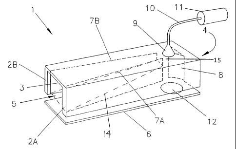
Figure 1 shows a perspective view,

Figure 2A shows a diagrammatic cross section view of waves in the chamber
prior
to air being compressed, and

Figure 2B shows a diagrammatic cross section view of waves in the chamber with
air compressed.

Referring to Figure 1 there is shown an apparatus for deriving energy from
waves.
The apparatus has an elongate chamber I adapted to float in water. Chamber 1
is formed
from a pair of side walls 2A, 2B spaced apart by a top plate 3. One end of the
side walls

are joined by an end wall 4 and the other end of side walls are spaced to
provide an inlet
port 5. A bottom plate 6 may span the edges of the side walls opposite the top
plate 3.
Chamber 1 includes a pair of internal tapering side plates 7A, 7B (shown in
dotted

lines) adjacent each side wall 2A, 2B to compress laterally the air in a wave
trough and
deliver the compressed air to a manifold 15. The bottom of the channel may be
the plate 6
or an inclined ramp 14.


CA 02368554 2001-10-30
WO 01/65112 PCT/GBOI/01012
-4-
A baffle 8 has the double function of restricting egress of air from the
compression

manifold 15 and dispersing remnant wave energy so that it is not reflected
back along the
chamber to interfere with the next incoming wave. The tapered sides of the
baffle may be
curved as shown.

An air outlet port 9 is mounted on the top plate 3 to which is attached an
airflow
pipe 10 connected to a prime mover 11. Outlet port 9 is in the compression
manifold 15
adjacent the baffle, and between the baffle and the inlet port. Wave water
outlets 12 are
provided in the side walls 2A, 2B adjacent the baffle 8.

Referring now to Figures 2A, 2B it will be seen that the chamber I may be
anchored to the sea bed by anchor and chain 13. The chamber is tethered from
the inlet
port so that the inlet port always faces the wavetrain.

Buoyancy for the chamber I is provided mostly by the side walls 2A, 2B, but
also
by the end wall 4. The side and end walls have a small water plane area such
that the
vertical oscillating movement of chamber 1 is substantially damped relative to
the height
of waves in the water in which it is floating,

In use waves travel through the inlet port and travel along the wave channel
created by the side plates 7A, 7B towards the compression manifold 15 and the
baffle 8.
As seen in Figure 2A a volume of air Z (in the trough behind a peak of wave X
hitting the

baffle and the following peak of wave Y) is fed into the manifold 15 under the
outlet port
9. As wave Y moves towards baffle 8, the volume of air Z is compressed into
the


WO 01/65112 CA 02368554 2001-10-30 PCT/GBOI/01012
-5-

manifold by the wave Y and forced out through the outlet port 9. Each wave
hitting the
baffle 8 is reflected normal to the direction of the wave train to disperse
the wave energy,
and excess water under pressure passes through water outlet 12.

It will be appreciated that the air between any two waves entering the chamber
I
will be compressed in the manifold 15 and expelled through the aperture 9. The
compressed air may be used to drive a prime mover 1 1 designed to generate
energy. A

non-return valve (not shown) may be positioned in the pipe 10 to take off air
when it
reaches a designated compression.

The invention may take a form different to that specifically described above.
In
particular the apparatus may be adjustable to suit different wave conditions.
For example
means may be provided to adjust the buoyancy of the chamber to adjust its
height in the
water to suit different wave heights, or means may be provided to adjust the
angle of taper
of the side plates 7A, 7B. It is thought that the taper of the side plates 7A,
7B may help to
compress the air to increase the peak pressure of air driven out through the
outlet port 9,

and adjustment of the taper of plates 7A, 7B may serve to give compression
ratios of e.g.
between 2:1 to 6:1. The position of baffle 8 may be adjustable along the
length of chamber
1, e.g. to suit different wavelengths. The bottom plate 6, or the ramp 14, may
also be
angled, and possibly adjustable like the side plates, to help compress the
air.

Also the apparatus may be of a simpler construction. For example the side
walls
2A, 2B may serve as a wave channel guide and the side plates 7A, 7B may not be
required.
The bottom plate 6 may not be required and the end wall 4 may serve as the
baffle instead
of there being a separate baffle.


WO 01/65112 CA 02368554 2001-10-30 pCT/GBO1/01012
-6-

It is envisaged that the apparatus of the invention may be produced in
different
sizes to suit different types of conditions, e.g. for estuary use or for ocean
use. The prime
mover 11 may generate electricity. Also two or more such apparatus may be
interconnected to supply a single source of compressed air to a prime mover.
The prime
mover may be positioned on or remote from any chamber 1.

It is also envisaged that two similar apparatus may be connected back to back,
possibly with a baffle unit in common, so that one delivers compressed air to
a reservoir
and the other extracts air to create a partial vacuum in a second reservoir. A
prime mover
may then be powered by the difference in pressure between the two reservoirs.

Because the chamber 1 may be anchored to the sea bed, the force on the chamber
I
is greatly reduced compared to hitherto known fixed constructions.

Representative Drawing
A single figure which represents the drawing illustrating the invention.
Administrative Status

For a clearer understanding of the status of the application/patent presented on this page, the site Disclaimer , as well as the definitions for Patent , Administrative Status , Maintenance Fee  and Payment History  should be consulted.

Administrative Status

Title Date
Forecasted Issue Date 2009-01-06
(86) PCT Filing Date 2001-02-28
(87) PCT Publication Date 2001-09-07
(85) National Entry 2001-10-30
Examination Requested 2005-02-14
(45) Issued 2009-01-06
Deemed Expired 2015-03-02

Abandonment History

There is no abandonment history.

Payment History

Fee Type Anniversary Year Due Date Amount Paid Paid Date
Application Fee $150.00 2001-10-30
Maintenance Fee - Application - New Act 2 2003-02-28 $50.00 2003-02-07
Maintenance Fee - Application - New Act 3 2004-03-01 $50.00 2004-02-13
Maintenance Fee - Application - New Act 4 2005-02-28 $50.00 2005-02-11
Request for Examination $400.00 2005-02-14
Registration of a document - section 124 $100.00 2005-02-14
Maintenance Fee - Application - New Act 5 2006-02-28 $100.00 2006-02-14
Maintenance Fee - Application - New Act 6 2007-02-28 $100.00 2007-01-17
Maintenance Fee - Application - New Act 7 2008-02-28 $100.00 2008-02-08
Final Fee $150.00 2008-10-17
Maintenance Fee - Patent - New Act 8 2009-03-02 $100.00 2009-02-17
Maintenance Fee - Patent - New Act 9 2010-03-01 $100.00 2010-01-08
Maintenance Fee - Patent - New Act 10 2011-02-28 $250.00 2011-02-17
Maintenance Fee - Patent - New Act 11 2012-02-28 $125.00 2012-02-27
Maintenance Fee - Patent - New Act 12 2013-02-28 $125.00 2013-01-30
Owners on Record

Note: Records showing the ownership history in alphabetical order.

Current Owners on Record
OFFSHORE WAVE ENERGY LIMITED
Past Owners on Record
KEMP, JOHN FREDERICK
Past Owners that do not appear in the "Owners on Record" listing will appear in other documentation within the application.
Documents

To view selected files, please enter reCAPTCHA code :


To view images, click a link in the Document Description column. To download the documents, select one or more checkboxes in the first column and then click the "Download Selected in PDF format (Zip Archive)" or the "Download Selected as Single PDF" button.

List of published and non-published patent-specific documents on the CPD .

If you have any difficulty accessing content, you can call the Client Service Centre at 1-866-997-1936 or send them an e-mail at CIPO Client Service Centre.


Document
Description 
Date
(yyyy-mm-dd) 
Number of pages   Size of Image (KB) 
Abstract 2001-10-30 1 60
Claims 2001-10-30 3 61
Description 2001-10-30 6 183
Drawings 2001-10-30 2 26
Representative Drawing 2001-10-30 1 12
Drawings 2007-07-10 2 25
Claims 2007-07-10 2 60
Cover Page 2002-04-19 1 41
Representative Drawing 2008-12-16 1 12
Cover Page 2008-12-16 2 45
Prosecution-Amendment 2007-01-17 3 107
Assignment 2005-02-14 2 62
PCT 2001-10-30 3 97
Assignment 2001-10-30 3 103
Fees 2003-02-07 1 33
Prosecution-Amendment 2007-07-10 8 283
Fees 2004-02-13 1 31
Prosecution-Amendment 2005-02-14 1 24
Fees 2005-02-11 1 26
Fees 2006-02-14 1 27
Fees 2007-01-17 1 29
Correspondence 2007-08-20 2 47
Fees 2008-02-08 1 35
Correspondence 2008-10-17 1 38
Fees 2009-02-17 1 34
Fees 2010-01-08 1 35
Fees 2012-02-27 1 163