Language selection

Search

Patent 2368603 Summary

Third-party information liability

Some of the information on this Web page has been provided by external sources. The Government of Canada is not responsible for the accuracy, reliability or currency of the information supplied by external sources. Users wishing to rely upon this information should consult directly with the source of the information. Content provided by external sources is not subject to official languages, privacy and accessibility requirements.

Claims and Abstract availability

Any discrepancies in the text and image of the Claims and Abstract are due to differing posting times. Text of the Claims and Abstract are posted:

  • At the time the application is open to public inspection;
  • At the time of issue of the patent (grant).
(12) Patent: (11) CA 2368603
(54) English Title: FUEL TANK WITH LID
(54) French Title: RESERVOIR A CARBURANT MUNI D'UN COUVERCLE
Status: Expired
Bibliographic Data
(51) International Patent Classification (IPC):
  • B60K 15/03 (2006.01)
(72) Inventors :
  • PALVOELGYI, SANDOR (Austria)
  • POZGAINER, GUNTHER (Austria)
(73) Owners :
  • TESMA MOTOREN- UND GETRIEBETECHNIK GMBH (Austria)
(71) Applicants :
  • TESMA MOTOREN- UND GETRIEBETECHNIK GMBH (Austria)
(74) Agent:
(74) Associate agent:
(45) Issued: 2010-03-23
(22) Filed Date: 2002-01-18
(41) Open to Public Inspection: 2002-07-19
Examination requested: 2007-01-17
Availability of licence: N/A
(25) Language of filing: English

Patent Cooperation Treaty (PCT): No

(30) Application Priority Data:
Application No. Country/Territory Date
GM 044/2001 Austria 2001-01-19

Abstracts

English Abstract

A fuel tank with an opening, on which a lid is mounted in a removable manner by means of thread or bayonet, is intended to provide a sustained and sealed closure under all conditions. For this purpose, two sealing rings are arranged between the sealing surfaces, the inner one being liquid-tight and the outer one being made of an elastomer with high permeation resistance. The sealing surfaces within the outer sealing ring have a narrow gap leading as far as the outer sealing ring, and the fuel tank has a reinforcement surrounding the opening.


French Abstract

Réservoir à carburant ayant un orifice, sur lequel est fixé un couvercle de manière amovible au moyen d'un fil ou d'une baïonnette, dans le but d'assurer une fermeture soutenue et étanche dans toutes les conditions. € cette fin, deux anneaux d'étanchéité sont placés entre les surfaces de scellement, celui à l'intérieur étant étanche aux liquides et celui à l'extérieur étant à base d'élastomère à haute résistance à la perméation. Les surfaces de scellement dans l'anneau d'étanchéité externe ont un écart étroit allant aussi loin que l'anneau de scellement externe, et le réservoir de carburant a un renforcement autour de l'orifice.

Claims

Note: Claims are shown in the official language in which they were submitted.


Claims

What is claimed is:


1. A fuel tank assembly comprising:
a wall for enclosing a fluid;
said wall having an upper wall and an inwardly flanged lip extending
downwardly
from said upper wall into said fuel tank forming an opening extending through
a portion of
said wall and defining a first sealing surface along the circumferential
periphery of said
lip;
a removable lid for closing said opening in said wall, said lid having an
outer
peripheral part defining a second sealing surface along the circumferential
periphery
thereof facing said first sealing surface when said lid is seated in said
opening;
first and second spaced apart radial grooves formed in at least one of said
first and
second sealing surfaces;
first and second sealing rings seated in said first and second grooves
respectively
for sealing engagement between said first and second sealing surfaces when
said lid is
closed against said opening;
a sealing gap formed between said first sealing surface and the part of said
second
sealing surface extending between said spaced apart radial grooves for
limiting the contact
surface area of fuel vapours with said second sealing ring and thereby
increase the
permeation resistance of said sealing engagement between said lid and said
opening; and
a reinforcement member including a planar portion fixedly secured to the
inside of
said upper wall and a shoulder portion extending downwardly from said planar
portion
forming a surrounding shoulder which supports said circumferential periphery
of said
inwardly flanged lip defining said opening for conically supporting said lip
against the
sealing forces between said first and second sealing surfaces from said lid
closing against
said opening.


-7-


2. A fuel tank assembly as set forth in claim 1 wherein said first and second
sealing
surfaces extend substantially parallel and conically inwardly into said
opening.


3. A fuel tank assembly as set forth in claim 2 wherein said first and second
grooves
extend radially around the circumference of said second sealing surface
defined by said
lid.


4. A fuel tank assembly as set forth in claim 3 wherein said reinforcement
member
includes an inwardly flanged collar and said peripheral part of said lid
includes an
outwardly flanged collar for overlapping engagement with said collar of said
reinforcement member to secure said lid against said opening.


5. A fuel tank assembly as set forth in claim 4 wherein said first sealing
ring is a liquid
seal seated in said first groove adjacent said opening of said fuel tank for
sealing liquid
fuel in said fuel tank.


6. A fuel tank assembly as set forth in claim 5 wherein said second sealing
ring is a fuel
vapour seal made of an elastomer with high permeation resistance seated in
said second
groove and spaced from said first sealing ring by said sealing gap for sealing
fuel vapour
in said fuel tank.


7. A fuel tank assembly comprising:
a wall for enclosing a fluid;
said wall having an inwardly flanged lip forming an opening extending through
a
portion of said wall and defining a first sealing surface along the
circumferential periphery
of said lip;
a removable lid for closing said opening in said wall, said lid having an
outer
peripheral part defining a second sealing surface along the circumferential
periphery
thereof facing said first sealing surface when said lid is seated in said
opening;
first and second spaced apart radial grooves formed in at least one of said
first and
second sealing surfaces;


-8-


first and second sealing rings seated in said first and second grooves
respectively
for sealing engagement between said first and second sealing surfaces when
said lid is
closed against said opening;
a sealing gap formed between said first sealing surface and the part of said
second
sealing surface extending between said spaced apart radial grooves for
limiting the contact
surface area of fuel vapours with said second sealing ring and thereby
increase the
permeation resistance of said sealing engagement between said lid and said
opening; and
a reinforcement member fixedly secured to the inside of said wall forming a
surrounding shoulder which supports said circumferential periphery of said
inwardly
flanged lip defining said opening for supporting said lip against the sealing
forces between
said first and second sealing surfaces from said lid closing against said
opening;
wherein said reinforcement member includes an inwardly flanged collar and said

peripheral part of said lid includes an outwardly flanged collar for
overlapping
engagement with said collar of said reinforcement member to secure said lid
against said
opening.


-9-

Description

Note: Descriptions are shown in the official language in which they were submitted.


CA 02368603 2002-01-18

FUEL TANK WITH LID
1. Field of the Invention

[0001] The present invention relates to a fuel tank for motor vehicle having
an
opening on which a lid is mounted in a removable manner by way of threads or
bayonet
wherein the opening and lid each have a sealing surface.

2. Background of the Invention

[0002] Fuel tank openings with lids can be used for different purposes, for
example, for filling the tank, but in particular for carrying out maintenance
work on
components situated inside the tank, for example, on liquid level indicators
or fuel pumps.

[0003] The lid is intended to seal the opening in a reliable manner, even
after
a lengthy period of operation, and to be easily removable. Irrespective of
whether the tank is
made of metal or plastic, it has a relatively thin wall, so that there is a
risk of the closing force
causing deformation of the edge. This leads to leakages. Sealing is a
particular problem is
these types of closures because light fuels are volatile and, as vapors, can
also diffuse through
solid bodies such as sealing rings. The available structural height is also
limited.

SUMMARY OF THE INVENTION

[0004] The present invention is intended to remedy these disadvantages and to
make available a fuel tank closure which provides sustained sealing under all
conditions.
[0005] According to one aspect of the invention, this is achieved by the fact

that a) two sealing rings are arranged between the sealing surfaces of the
opening and lid, an
inner sealing ring being liquid-tight and an outer sealing ring being made of
an elastomer
with high permeation resistance, b) the sealing surfaces within the outer
sealing ring have a
-1-


CA 02368603 2002-01-18

narrow gap leading as far as the outer sealing ring, and c) the fuel tank has
a reinforcement
surrounding the opening.

[0006] The liquid seal is provided by the inner sealing ring, while the outer
sealing ring provides a vapor barrier. For this purpose, the outer sealing
ring is not only
made of a suitable material, but, because of the narrow gap leading up to it,
also has a small
contact surface with the vapor waiting on its inner side. Since the permeation
begins on the
surface of the sealing ring, the small contact surface means a further
reduction in permeation.
The reinforcement ensures that the sealing surfaces are not deformed by the
closure forces
and do not loose their leak tightness.

[0007] According to one embodiment of the invention, the sealing surfaces
extend substantially conically inward, and the sealing surface of the lid has
grooves for
receiving and seating the sealing rings. The conical shape affords sufficient
sealing forces at
low clamping forces and saves space since the cone can project into the inside
of the tank.

[0008] According to another embodiment of the invention, the sealing
surfaces extend inward with their axes substantially normal, and the sealing
surface of the
fuel tank has grooves for receiving and seating the sealing rings. In this
position of the
sealing surfaces, the contact pressures on the two sealing rings can be
particularly finely
matched to one another and the sealing rings can be fitted and inspected
without risk of
darnage.

[0009] The reinforcement is preferably a part which is welded onto the wall of
the tank, surrounds the opening and includes one half of the thread or
bayonet. The closure
forces are thus taken up directly by the reinforcement and not via the tank
wall. The stiffness
thereby obtained in the area around the opening contributes to the leak
tightness.

[00010] In one configuration, the reinforcemerit is arranged on the inside of
the
wall of the tank, and the edge of the opening is designed as a sealing
surface. Thus, the leak
-2-


CA 02368603 2002-01-18

tightness is not dependent on the nature of the connection between the
reinforcement and the
tank wall. The forces are particularly favorable, especially in the case of
conical sealing
surfaces, when the edge of the opening for forming the sealirig surface is
flanged inward, and
the reinforcement forms a surrounding shoulder which supports the inwardly
flanged edge of
the opening, especially when the reinforcement inwardly adjoining the
surrounding shoulder
also forms one half of the thread or bayonet closure.

[00011] In another configuration, the reinforcement is arranged on the outside
of the wall of the tank and a sealing surface is formed on it. This variant is
simpler from the
production point of view and ensures the shape stability of the one sealing
surface, which fact
contributes to sustained leak tightness. In a refinement thereof, the
reinforcement has a
surrounding rectangular profile whose vertical surfaces are connected to the
tank and whose
lid surface has grooves for receiving the sealing rings. This affords a
particularly stiff
bearing of the sealing rings and thus particularly good sealing. In order to
avoid excessive
pressing of the sealing rings, a contact bead can also be provided.

[00012] In order to avoid the penetration of moisture or dirt, and thus
corrosion,
the lid can also be provided with a lip seal on its outer edge.

BRIEF DESCRIPTION OF THE DRAWINGS

[00013] Other advantages of the present invention will be readily appreciated
as the same becomes better understood by reference to the following detailed
description
when considered in connection with the accompanying drawings wherein:

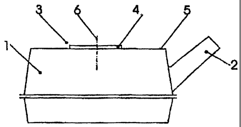
[00014] Figure 1 is a side view of a conventional fuel tank with an opening
and
lid;

[00015] Figure 2 is a cross-sectional view of the fuel tank opening and lid;
and
-3-


CA 02368603 2002-01-18
` 5.

[00016] Figure 3 is a cross-sectional view of an alternative embodiment of the
fuel tank opening and lid.

DETAILED DESCRIPTION OF THE INVENTION

[00017] Referring to Figure 1, a fuel tank for storing fuel is generally shown
at
1. The fuel tank 1 has a filler attachment 2 and, in its upper wall 5, an
opening 3 which is
closed by a lid 4. The lid 4 may have measuring or pumping elements on its
inside and may
be removed for repair or maintenance purposes. Tn plan view, the lid 4 is
symmetrical, in
particular circular, as is indicated by broken line showing the axis of
symmetry or axis of
rotation 6.

[00018] In the embodiment shown in Figure 2, the upper wall 5 of the fuel tank
1 has a raised portion 10 which surrounds the opening 3 which, further to the
inside, is
substantially conically inwardly flanged forming a lip 11 presenting the edge
of the opening
3. The surface of the conically inwardly flanged lip 11 directed toward the
center axis of
rotation 6 forms the first sealing surface 12. A reinforcement 13 similarly
surrounding the
opening 3 is welded to the upper wall 5 via a planar portion 14. For this
purpose, any
suitable welding method can be used, for example, resistance welding or spot
welding.
Adjoining the planar portion 14 toward the inside, the reinforcement 13 forms
a shoulder 15
which can support the conically inwardly flanged lip 11 of the wall 5 against
the sealing
forces acting on the latter. Further inward still, the reinforcement 13 is
flanged inward to
form a collar 16 which forms the first half of a bayonet closure.

[00019] The lid 4 has a peripheral part 18 which in its lower part is flanged
outward to form a collar 17 which forms the second half of the bayonet closure
and
cooperates with the first half thereof. The peripheral part 18 further forms a
conical second
sealing surface 19. Conical should be understood as both conically in the
exact geometric
-4-


CA 02368603 2002-01-18
4

sense and also in general as an inwardly and downwardly extending narrowing.
In this
second sealing surface 19 there is provided a first groove 20 for receiving
and seating a first
sealing ring 22 and a second groove 21 for receiving and seating a second
sealing ring 23.
When the lid 4 is closed, these sealing rings 22, 23 bear tightly on the first
sealing surface 12
of the conically inwardly flanged lip 11.

[00020] The first sealing ring 22 provides the liquid seal and the second
sealing
ring 23, which is arranged downstream of the first sealing ring 22 in the
direction of flow, or
below, provides the seal against permeation of fuel vapors. The second sealing
ring 23 is
made of an elastomer with high permeation resistance. In addition, the
peripheral part 18 of
the lid 4 between the two grooves 20, 21 forms a narrow sealing gap 24 with
the conically
inwardly flanged lip 11. The narrowness of this sealing gap 24 has the effect
that fuel vapors
come into contact only with a very small surface of the second sealing ring
23, and the
permeation entry surface is thus very small, by which means the permeation
resistance of the
second sealing ring 23 is further increased. Finally, a lip seal. 25 is also
provided on the upper
edge of the peripheral part 18, which lip seal 25 bears on the raised portion
10 of the wall 5
and thus prevents penetration of dirt and moisture into the opening 3 and
between the sealing
surfaces 12, 19.

[00021] In the alternative embodiment of Figure 3, the wall 5 forms an
inwardly flanged edge 30 which surrounds the opening 3 and onto which a
reinforcement 31
is externally applied and welded. The reinforcement 31 has a substantially
rectangular profile
extending around the center axis 6 and with an inner vertical surface 32 which
is welded
tightly to the flanged edge 30, and with an outer vertical surface 33 which is
likewise
cylindrical and ends in an outwardly flanged edge with weld bosses 34 which
are likewise
welded to the wa115. The approximately rectangular profile of the
reinforcement 31 forms, at
the top, a stop bead 35 and, adjoining the latter toward the inside, a first
sealing surface 36
-5-


CA 02368603 2002-01-18

which has a substantially normal axis, but can also be slightly conical. In
this first sealing
surface 36, there is once again a first groove 37 for receiving a first
sealing ring 39 and a
second groove 38 for receiving a second sealing ring 40.

[00022] On its radius corresponding to the radius of the first sealing surface
36,
a lid 41 is drawn downward to a second sealing surface 42. This second sealing
surface 42
again forms, with the first sealing surface 36, a narrow gap 47, as was
described with
reference to the previous embodiment. The lid 41 is further welded to a lid
flange 43 and
forms a reinforcing rib 44 over the second sealing surface 42. These together
form a closed
profile which gives the lid 41 the stiffness required for an exact fitting of
the sealing surfaces
36, 42. The lid flange 43 continues downward to a first threaded part 45, of
which only one
thread is shown. With this, the lid is screwed onto the second threaded part
46 in the outer
vertical surface 33 of the reinforcement 31.

[00023] The invention has been described in an illustrative manner, and it is
to
be understood that the terminology, which has been used, it intended to be in
the nature of
words of description rather than of limitation.

[00024] Many modifications and variations of the present invention are
possible in light of the above teachings. It is, therefore, to be understood
that within the
scope of the appended claims, the invention may be practiced other than as
specifically
described.

-6-

Representative Drawing
A single figure which represents the drawing illustrating the invention.
Administrative Status

For a clearer understanding of the status of the application/patent presented on this page, the site Disclaimer , as well as the definitions for Patent , Administrative Status , Maintenance Fee  and Payment History  should be consulted.

Administrative Status

Title Date
Forecasted Issue Date 2010-03-23
(22) Filed 2002-01-18
(41) Open to Public Inspection 2002-07-19
Examination Requested 2007-01-17
(45) Issued 2010-03-23
Expired 2022-01-18

Abandonment History

There is no abandonment history.

Payment History

Fee Type Anniversary Year Due Date Amount Paid Paid Date
Registration of a document - section 124 $100.00 2002-01-18
Application Fee $300.00 2002-01-18
Maintenance Fee - Application - New Act 2 2004-01-19 $100.00 2003-12-22
Maintenance Fee - Application - New Act 3 2005-01-18 $100.00 2004-12-23
Maintenance Fee - Application - New Act 4 2006-01-18 $100.00 2005-12-20
Maintenance Fee - Application - New Act 5 2007-01-18 $200.00 2006-12-20
Request for Examination $800.00 2007-01-17
Maintenance Fee - Application - New Act 6 2008-01-18 $200.00 2007-12-21
Maintenance Fee - Application - New Act 7 2009-01-19 $200.00 2008-12-12
Final Fee $300.00 2009-11-12
Maintenance Fee - Application - New Act 8 2010-01-18 $200.00 2009-12-11
Maintenance Fee - Patent - New Act 9 2011-01-18 $200.00 2010-12-17
Maintenance Fee - Patent - New Act 10 2012-01-18 $250.00 2011-12-13
Maintenance Fee - Patent - New Act 11 2013-01-18 $250.00 2013-01-07
Maintenance Fee - Patent - New Act 12 2014-01-20 $250.00 2014-01-06
Maintenance Fee - Patent - New Act 13 2015-01-19 $250.00 2015-01-05
Maintenance Fee - Patent - New Act 14 2016-01-18 $250.00 2016-01-04
Maintenance Fee - Patent - New Act 15 2017-01-18 $450.00 2017-01-09
Maintenance Fee - Patent - New Act 16 2018-01-18 $450.00 2018-01-08
Maintenance Fee - Patent - New Act 17 2019-01-18 $450.00 2019-01-07
Maintenance Fee - Patent - New Act 18 2020-01-20 $450.00 2020-01-06
Owners on Record

Note: Records showing the ownership history in alphabetical order.

Current Owners on Record
TESMA MOTOREN- UND GETRIEBETECHNIK GMBH
Past Owners on Record
PALVOELGYI, SANDOR
POZGAINER, GUNTHER
Past Owners that do not appear in the "Owners on Record" listing will appear in other documentation within the application.
Documents

To view selected files, please enter reCAPTCHA code :


To view images, click a link in the Document Description column. To download the documents, select one or more checkboxes in the first column and then click the "Download Selected in PDF format (Zip Archive)" or the "Download Selected as Single PDF" button.

List of published and non-published patent-specific documents on the CPD .

If you have any difficulty accessing content, you can call the Client Service Centre at 1-866-997-1936 or send them an e-mail at CIPO Client Service Centre.


Document
Description 
Date
(yyyy-mm-dd) 
Number of pages   Size of Image (KB) 
Representative Drawing 2002-04-08 1 5
Cover Page 2002-07-15 1 31
Abstract 2002-01-18 1 18
Description 2002-01-18 6 288
Claims 2002-01-18 3 85
Drawings 2002-01-18 1 30
Office Letter 2021-05-25 2 194
Office Letter 2021-05-26 2 200
Claims 2009-05-07 3 113
Representative Drawing 2010-02-22 1 5
Cover Page 2010-02-22 1 32
Assignment 2002-01-18 4 178
Correspondence 2009-07-15 1 31
Prosecution-Amendment 2007-01-17 1 24
Prosecution-Amendment 2007-02-27 1 27
Correspondence 2008-10-08 17 613
Correspondence 2008-11-13 1 18
Prosecution-Amendment 2008-11-14 2 47
Correspondence 2008-11-14 1 26
Prosecution-Amendment 2009-05-07 5 169
Correspondence 2009-08-18 2 72
Correspondence 2009-11-12 1 28
Assignment 2002-01-18 5 222
Correspondence 2012-01-11 1 18
Correspondence 2012-01-13 1 19
Correspondence 2011-12-13 19 698