Note: Descriptions are shown in the official language in which they were submitted.
CA 02368736 2001-11-05
WO 01/00973 PCT/US00/40174
SYSTEM AND METHOD FOR ENHANCED
ENGINE MONITORING AND PROTECTION
TECHNICAL FIELD
The present invention relates to a system and method for monitoring
engine operation and providing information to the operator or controlling the
engine
based on engine operating conditions.
BACKGROUND ART
In the control of internal combustion engines, the conventional
practice utilizes electronic control units, volatile and non-volatile memory,
input and
output driver circuitry, and a processor capable of executing a stored
instruction set,
to control the various functions of the engine and its associated systems. A
particular
electronic control unit communicates with numerous sensors, actuators, and
other
control units necessary to effect various control and information functions of
the
engine and/or vehicle.
Various sensors are used to detect engine operating conditions which
may affect control of the engine and/or vehicle. To provide information to the
operator relative to engine operating conditions and/or control the engine
based on
current engine operating conditions, conventional practice utilizes an engine
operating parameter such as a coolant temperature or pressure, and compares
the
engine operating parameter with a limit which may vary as a function of a
different
engine operating parameter, such as throttle position, engine speed, or engine
torque.
If the engine operating parameter drops below the limit, the engine may
automatically shut down, without first informing the operator, to protect the
engine
from damage.
Depending upon the particular engine or vehicle operating conditions,
it may be undesirable to shut down the engine without first providing the
vehicle
-1-
CA 02368736 2001-11-05
WO 01/00973 PCT/US00/40174
operator an opportunity to take corrective action, or to override the
requested engine
shutdown. Furthermore, it is desirable to have sufficient confidence in the
accuracy
of sensor signals and other indicators which provide signals indicative of
current
engine operating conditions so that operator information or subsequent engine
control
is reliably performed.
Some prior art control systems provide a pressure limit or threshold
as a function of engine speed. However, such systems may experience false
alarms
shortly after engine start-up or during other transient conditions where
engine fluid
pressures vary rapidly.
DISCLOSURE OF INVENTION
It is therefore an object of the present invention to provide a method
and system for improving engine operating information relative to at least one
engine
fluid pressure.
Another object of the present invention is to provide a system and
method for providing information and/or controlling the engine based on at
least one
fluid pressure selected from the group including engine coolant pressure and
engine
oil pressure.
An additional object of the present invention is to provide information
relative to engine operating conditions prior to engine shutdown so the
operator has
an opportunity to take corrective action.
Another object of the present invention is to provide a customer
configurable fluid pressure parameter.
In carrying out the above objects and other objects and features of the
present invention a method for monitoring engine operating fluid pressures
and/or
controlling the engine based on at least one fluid pressure include measuring
an
engine fluid pressure, determining a value of an engine operating parameter,
and
-2-
CA 02368736 2001-11-05
WO 01/00973 PCT/US00/40174
determining whether the engine fluid pressure has crossed a first threshold
corresponding to the determined value of the engine operating parameter. The
method further determines whether the engine fluid pressure has crossed a
second
threshold corresponding to the current value of the engine operating
parameter. An
operator information display or device is activated when the fluid pressure
crosses
the first threshold but has not yet crossed the second threshold. An engine
shut-
down sequence is activated when the engine fluid pressure crosses the second
threshold. In one embodiment of the present invention, the second threshold is
determined based on a fixed offset from the first threshold.
In further carrying out the above objects and other objects, features
and advantages of the invention, a computer readable storage medium is
provided.
The computer readable storage medium has information stored thereon
representing
instructions executable by a computer for monitoring engine operating fluid
pressures
and/or controlling the engine based on at least one fluid pressure. The
computer
readable storage medium includes instructions for measuring an engine fluid
pressure, determining a value of an engine operating parameter, and
determining
whether the engine fluid pressure has crossed a first threshold corresponding
to the
determined value of the engine operating parameter. The computer readable
storage
medium also includes instructions for determining whether the engine fluid
pressure
has crossed a second threshold corresponding to the current value of the
engine
operating parameter and instructions for activating an operator information
display
or device when the fluid pressure crosses the first threshold but has not yet
crossed
the second threshold. In addition, the computer readable storage medium
includes
instructions for performing an engine shut-down sequence when the engine fluid
pressure crosses the second threshold.
The present invention further includes a system for monitoring engine
operation and providing enhanced engine protection. The system includes at
least
one engine fluid pressure sensor for providing an indication of a
corresponding
engine fluid pressure. Preferably, the pressure sensors include an engine
coolant
pressure sensor for measuring an engine coolant pressure and an engine oil
pressure
sensor for measuring an engine oil pressure. The system also includes a
-3-
CA 02368736 2001-11-05
WO 01/00973 PCT/US00/40174
microprocessor in communication with the pressure sensors for determining
whether
at least one of the pressures has crossed a corresponding pressure threshold.
The
electronic control unit includes control logic for generating an engine
warning signal
if any of the fluid pressures have crossed corresponding pressure threshold,
and for
shutting down the engine when certain fluid pressures cross a corresponding
second
threshold to reduce the potential for significant engine damage.
The advantages accruing to the present invention are numerous. For
example, the present invention provides improved engine monitoring which
provides
the operator with a warning before engine operating conditions indicate the
engine
should be shut down. In one embodiment, the present invention provides a
second
threshold while minimizing memory consumption and calibration time by
utilizing
a fixed offset from the first threshold. The present invention is applicable
to any
engine fluid pressure monitoring and control based on the engine fluid
pressure(s).
For example, engine coolant pressure, innercooler coolant pressure, oil
pressure, and
the like.
The above objects and other objects, features, and advantages of the
present invention are readily apparent from the following detailed description
of the
best mode for carrying out the invention when taken in connection with the
accompanying drawings.
BRIEF DESCRIPTION OF DRAWINGS
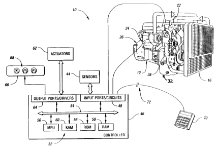
FIGURE 1 is a schematic diagram of one embodiment for an engine
monitoring and protection system based on engine fluid pressure according to
the
present invention;
FIGURE 2 is a graph depicting the warning pressure threshold and the
engine shut-down pressure threshold curves, according to the present
invention; and
FIGURE 3 is a block diagram illustrating operation of a system or
method according to the present invention for engine monitoring and
protection.
-4-
CA 02368736 2001-11-05
WO 01/00973 PCT/US00/40174
BEST MODE FOR CARRYING OUT THE INVENTION
Referring now to Figure 1, a system for monitoring engine operation
based on at least one fluid pressure according to the present invention is
shown.
Preferably, the at least one fluid pressure includes the coolant pressure and
oil
pressure. The system, generally indicated by reference numeral 10, includes an
engine 12 having a plurality of cylinders. In a preferred embodiment, engine
12 is
a multi-cylinder compression ignition internal combustion engine, such as a
four, six,
eight, twelve, sixteen or twenty-four cylinder diesel engine, for example. The
system further includes an engine coolant heat exchanger 16.
As also illustrated in Figure 1, system 10 includes an engine coolant
pressure sensor 22, an oil pressure sensor 24, an engine coolant pump 28, and
an
engine oil pan 32.
Engine coolant heat exchanger 16 removes heat from the engine
coolant using a conventional heat exchanger configuration as well known in the
art.
Preferably, the engine coolant sensor 22 measures the engine coolant pressure
as the
coolant exits the engine and travels toward heat exchanger 16. This location
typically exhibits the maximum pressure of the engine coolant pressure
relative to all
other points within the cooling circuit. Engine coolant water pump 28
circulates the
engine coolant through engine block 26 and through engine coolant heat
exchanger
16. Oil pressure sensor 24 measures the oil pressure of the engine lubricating
oil.
Oil pressure sensor 24 is preferably located in the engine crankcase near the
crankshaft bearings.
System 10 may also include various other sensors 44 for generating
signals indicative of corresponding engine conditions or parameters of engine
12 or
of the vehicle (not shown). Sensors 44 may include appropriate sensors for
providing signals indicative of boost pressure, oil temperature, coolant
temperature,
oil level, fuel pressure, vehicle speed, and coolant level. Likewise, various
switches
connected to an operator interface may be provided to select various optional
engine
-5-
CA 02368736 2001-11-05
WO 01/00973 PCT/US00/40174
operating modes including stop engine override, selection and setting of
cruise
control, and the like. Engine and/or vehicle operating parameters or
conditions may
also be calculated, determined, or inferred based on one or more of the sensed
parameters for operating conditions indicated by sensors 44.
Sensors 22, 24, and 44 are in electrical communication with a
controller 46 via input ports and/or conditioning circuitry 48. A preferred
embodiment of controller 46 includes a DDEC controller available from Detroit
Diesel Corporation, Detroit, Michigan. Various other features of this
controller are
described in detail in U.S. Patent Nos. 5,477,827 and 5,445,128, the
disclosures of
which are hereby incorporated by reference in their entirety. Controller 46
preferably includes a microprocessor 50 in communication with various computer
readable storage media 52 via data and control bus 54. Computer readable
storage
media 52 may include any number of known devices which function as a read only
memory (ROM) 56, random access memory (RAM) 58, keep alive memory (KAM)
60 and the like. The computer readable storage media may be implemented by any
of a number of known physical devices capable of storing data representing
instructions executable via a computer such as controller 46. Known devices
may
include but are not limited to, PROM, EPROM, EEPROM, flash memory, and the
like in addition to magnetic, optical, and combination media capable of
temporary
or permanent data storage.
Computer readable storage media 52 include data representing
program instructions (software), calibrations, operating variables and the
like used
in conjunction with associated hardware to effect control of various systems
and
subsystems of the vehicle, such as engine 12. Controller 46 receives signals
from
sensors 22, 24, and 44 via input ports 48 and generates output signals which
may be
provided to various actuators 62 and/or components via output ports 64.
Signals may
also be provided to a display device 66 which may include various indicators
such
as lights 68 to communicate information relative to system operation to the
operator
of the vehicle. Of course, alphanumeric, audio, video, or other displays or
indicators may be utilized if desired.
-6-
CA 02368736 2001-11-05
WO 01/00973 PCT/US00/40174
With continuing reference to Figure 1, control logic implemented by
controller 46 and associated hardware and/or software is used to provide
engine
monitoring and protection according to the present invention. In a preferred
embodiment, the control logic implemented by controller 46 monitors engine
operation based on at least one fluid pressure and corresponding programmable
or
selectable pressure thresholds. Preferably, controller 46 determines whether
the
coolant pressure as indicated by the coolant pressure sensor 22 and the oil
pressure
as indicated by oil pressure sensor 24 have crossed respective pressure
thresholds.
As will be appreciated by one of ordinary skill in the art, control logic
according to
the present invention is preferably implemented by a programmed microprocessor
operating as described in detail below. However, various alternative hardware
and/or software may be used to implement the control logic without departing
from
the spirit or scope of the present invention.
A data, diagnostics, and programming interface 70 may be selectively
connected to controller 46 via a connector 72 to exchange various information
between controller 46 and the operator and/or service personnel. Interface 70
may
be used to change values within the computer readable storage media 52, such
as
configuration settings, calibration variables, look-up table values, control
logic, and
the like. For example, interface 70 may be used to program or select pressure
thresholds for each of the monitored fluid pressures according to the present
invention.
With reference to Figure 2, a chart of engine fluid pressure as a
function of an engine operating parameter (for example engine speed) is shown.
In
particular, a first pressure threshold 60 and a second pressure threshold 62
which
vary as a function of engine speed are illustrated. The first pressure
threshold 60 as
well as the second pressure threshold 62 are developed through empirical
testing
and/or simulated computer testing of the engine, as well known in the art. In
one
embodiment, first threshold 60 represents a warning pressure threshold which
is
determined based on a constant offset 64 relative to the second threshold 62
which
represents an engine shut-down pressure threshold. In this embodiment, the
offset
pressure is typically 5 PSI. Offset pressure 64 in combination with engine
shutdown
_7_
CA 02368736 2001-11-05
WO 01/00973 PCT/US00/40174
pressure represented by threshold 62 provides a threshold over a range of
engine
speeds from idle to the maximum rated engine speed, where an engine warning
signal will be asserted.
As will be appreciated by one of ordinary skill in the art, the first and
second thresholds may represent minimum or maximum thresholds used to monitor
engine operation. For the embodiment of the invention illustrated in Figure 2,
thresholds 60 and 62 represent minimum thresholds such that the normal
operating
conditions for engine fluid pressures would be above first threshold 60.
Depending
on the particular application, first and second thresholds 60 and 62 may
represent
maximum or upper thresholds such that the normal operating conditions would be
below second threshold 62. According to one preferred embodiment of the
present
invention, at least one of the thresholds is generated using a fixed offset
from one of
the other thresholds which includes values corresponding to various engine
operating
conditions, preferably stored in a look-up table referenced or indexed by
another
engine operating parameter.
In one embodiment of the present invention, a timer or counter is used
to provide an averaging function and/or hysteresis in determining whether to
activate
a warning or initiate an engine shut down sequence. Depending upon the
particular
application, various types of timers and/or counters may be utilized. For
example,
an integrating timer/counter may be utilized which provides an averaging
function
for the pressure signal. When controller 46 determines that a pressure signal
has
crossed a corresponding threshold, such as threshold 60, the timer/counter
begins
incrementing and accumulating time. When the pressure signal crosses the
threshold
in the opposite direction, the timer/counter begins decrementing (to a minimum
value
of zero). The warning signal or shutdown sequence is not triggered unless the
timer/counter reaches some predetermined time or value. Alternatively, a
count/reset timer/counter may be used which begins incrementing when the
threshold
is crossed in one direction and resets to zero when the threshold is crossed
in the
opposite direction. Of course, for either timer/counter, the behavior of the
timer/counter depends on whether the threshold is an upper/maximum or
lower/minimum threshold.
_g_
CA 02368736 2001-11-05
WO 01/00973 PCT/US00/40174
In a preferred embodiment of the present invention, engine monitoring
includes determining when any one of the monitored fluid pressures is below
its
associated pressure threshold for the current engine operating conditions. For
example, if either the engine coolant pressure or the engine oil pressure is
below its
associated first threshold corresponding to the current engine speed for a
certain
time, an appropriate signal is generated to activate a warning device or
message.
While calibrations will vary by application, typical threshold values for
coolant
pressure and oil pressure are 75 PSI and 150 PSI, respectively. However, in
one
embodiment of the present invention, each of the pressure thresholds may be
set to
any value between 0 PSI and 255 PSI since one byte of memory is allocated to
each
calibration and scaled accordingly. In this embodiment, when controller 46
determines that all of the monitored fluid pressures are above the warning
pressure
threshold 60, engine malfunction is no longer indicated and the respective
signals are
not asserted.
Referring now to Figure 3, a flow chart illustrating operation of a
system or method for detecting an engine malfunction according to the present
invention. As will be appreciated by one of ordinary skill in the art, the
flow chart
represents control logic which may be implemented or effected in hardware,
software, or a combination of hardware and software. The various functions are
preferably effected by a programmed microprocessor such as the DDEC
controller,
but may include one or more functions implemented by dedicated electric,
electronic,
or integrated circuits. As will also be appreciated, the control logic may be
implemented using any one or a number of known programming and processing
techniques or strategies, and is not limited to the order or sequence
illustrated here
for convenience only. For example, interrupt or event driven processing is
typically
employed in real-time control applications, such as control of the vehicle
engine or
transmission. Likewise, parallel processing, multitasking, or multithreaded
systems
and methods may be used to accomplish the objectives, features, and advantages
of
the present invention. The present invention is independent of the particular
programming language, operating system, processor, or circuitry used to
implement
the control logic illustrated.
-9-
CA 02368736 2001-11-05
WO 01/00973 PCT/US00/40174
With continuing reference to Figure 3, an engine fluid pressure (EFP)
is measured as represented by block 200. The engine fluid may be engine
coolant,
engine oil, or other engine fluid indicative of engine operating conditions.
An
engine operating parameter such as engine speed, throttle position, or the
like is
determined as represented by block 202. EFP is compared to a first threshold
60
which represents the engine warning pressure threshold in this embodiment, as
represented by block 204. If EFP has crossed the first threshold, i.e. if EFP
is
below the engine warning pressure threshold, control passes to block 206 where
controller 46 determines whether EFP has crossed second threshold 62 as
represented
by block 206. If EFP is below the engine shut-down pressure threshold, the
engine
shut down signal is asserted as represented by block 208. Depending upon the
particular application and the particular fluid pressure being monitored,
engine
shutdown may be performed by an external device as represented by block 210 or
by the engine controller. For example, the engine controller may ramp down the
available engine torque and then cut off fuel supplied to the cylinders to
stall the
engine. The operator may be provided an opportunity to override the engine
shut-
down using an appropriate switch or appropriate actuation of the accelerator
pedal.
The engine signal may also be recorded as a code in non-volatile memory to
assist
maintenance personnel in diagnosing any unusual engine operating conditions.
In
one embodiment, diagnostic information including the number of engine hours,
the
most recent reset, total time of warning/shutdown signal, and most extreme
value of
monitored fluid pressure are also stored for subsequent troubleshooting.
If EFP has crossed the first threshold but has not crossed the second
threshold, an engine warning signal is asserted as represented by block 212
which
activates an associated indicator represented by block 214. The process
repeats at
predetermined periodic time intervals while the engine is running as the
microprocessor continues to execute the instructions and re-evaluate the
engine
operating conditions.
As such, the present invention provides improved engine monitoring
which provides the operator with a warning before engine operating conditions
indicate the engine should be shut down. The present invention provides first
and
-10-
CA 02368736 2001-11-05
WO 01/00973 PCT/US00/40174
second thresholds which may function as either upper/maximum or lower/minimum
thresholds. In one embodiment, the present invention provides a second
threshold
while minimizing memory consumption and calibration time by utilizing a fixed
offset from the first threshold.
While embodiments of the invention have been illustrated and
described, it is not intended that these embodiments illustrate and describe
all
possible forms of the invention. Rather, the words used in the specification
are
words of description rather than limitation, and it is understood that various
changes
may be made without departing from the spirit and scope of the invention.
-11-