Note: Descriptions are shown in the official language in which they were submitted.
CA 02368783 2001-09-26
WO 00/60340 PCT/KR00/00313
1
ELECTROCHEMICAL BIOSENSOR TEST STRIP, FABRICATION METHOD
THEREOF AND ELECTROCHEMICAL BIOSENSOR
TECHNICAL FIELD
The present invention relates to an electrochemical biosensor test strip for
quantitative analysis of analytes of interest, a method for fabricating the
same, and
an electrochemical biosensor using the same.
BACKGROUND ART
In the medical field, electrochemical biosensors are extensively used to
analyze biomaterials, including blood. Of them, enzyme-utilizing
electrochemical biosensors are most predominant in hospital or clinical
laboratories because they are easy to apply and superior in measurement
sensitivity, allowing the rapid acquisition of test results. For
electrochemical
biosensors, electrode methods have recently been extensively applied. For
example, in an electrode system established by screen printing, the
quantitative
measurement of an analyte of interest can be achieved by fixing a reagent
2 0 comprising an enzyme onto the electrodes, introducing a sample, and
applying an
electric potential across the electrodes.
An electrochemical biosensor using such an electrode method may be
referred to U. S. Pat. No. 5,120,420, which discloses an electrochemical
biosensor
test strip taking advantage of a capillary space for the introduction of
analytes,
teaching the use of a spacer between an insulating substrate and a cover to
form the
capillary space.
Another electrochemical biosensor test strip can be found in U. S. Pat. No.
5,437,999, in which a patterning technique, typically used in the PCB
industry, is
newly applied for the fabrication of an electrochemical biosensor, leading to
an
achievement of precisely defined electrode areas. This electrochemical
biosensor
test strip is allegedly able to precisely determine analyte concentrations on
a very
small sample size.
With reference to Fig. 1, there is an opposing electrode type of an
electrochemical biosensor test strip described in U. S. Pat. No. 5,437,999,
specified
by a disassembled state in an exploded perspective view of Fig. lA and by an
assembled state in a perspective view of Fig. 1B. Typically, these sensors
CA 02368783 2001-09-26
WO 00/60340 PCT/KR00/00313
2
perform an electrochemical measurement by applying a potential difference
across
two or more electrodes which are in contact with a reagent and sample. As seen
in the figure, the electrochemical biosensor test strip comprises two
electrodes: a
working electrode on which reactions occur and a reference electrode which
serves
as a standard potential.
There are two ways of arranging such working and reference electrodes.
One is of an opposing electrode type just like that shown in Fig. 1 A, in
which a
working electrode formed substrate is separated from a reference electrode by
a
spacer in a sandwich fashion. The other is of an adjacent type in which a
working
and a reference electrode both are fabricated on the same substrate side-by-
side in
a parallel fashion. U. S. Pat. No. 5,437,999 also discloses an adjacent
electrode
electrochemical biosensor, adopting a spacer that separates an insulating
substrate,
on which the electrodes are fabricated, from another insulating substrate,
which
serves as a cover, forming a capillary space.
In detail, referring to Fig. 1, a reference electrode-formed substrate, that
is, a reference electrode element 10, is spatially separated from a working
electrode-formed substrate, that is a working electrode element 20 by a spacer
16.
Normally, the spacer 16 is affixed to the reference electrode element 10
during
fabrication, but shown separate from the reference electrode element 10 in
Fig. lA.
2 0 A cutout portion 13 in the spacer 16 is situated between the reference
electrode
element 10 and the working element electrode 20, forming a capillary space 17.
A first cutout portion 22 in the working electrode element 20 exposes a
working
electrode area, which is exposed to the capillary space 17. When being affixed
to
the reference electrode element 10, a first cutout portion 13 in the spacer 16
2 5 defines a reference electrode area 14, shown in phantom lines in Fig. 1,
which is
also exposed to the capillary space 17. Second cutout portions 12 and 23
expose
a reference electrode area 11 and a working electrode area 21 respectively,
serving
as contact pads through which an electrochemical biosensor test strip 30, a
meter
and a power source are connected to one another.
30 In an assembled state as shown in Fig. 1B, the electrochemical biosensor
test strip 30 has a first opening 32 at its one edge. Further, a vent port 24
in the
working electrode element 20 may be incident to a vent port 15 in the
reference
electrode element 10 so as to provide a second opening 32. In use, a sample
containing an analyte may be introduced into the capillary space 17 via either
the
3 5 opening 31 or 32. In either case, the sample is spontaneously drawn into
the
electrochemical biosensor test strip by capillary action. As a result, the
CA 02368783 2001-09-26
WO 00/60340 PCT/KR00/00313
3
electrochemical biosensor test strip automatically controls the sample volume
measured without user intervention.
However, preexisting commercially available electrochemical biosensor
test strips, including those described in the patent references supra, suffer
from a
serious problem as follows: because electrodes are planarity fabricated on
substrates and reagents, including enzymes, are immobilized on the electrodes,
liquid phases of the reagents are feasible to flow down during the
immobilization,
so that they are very difficult to immobilize in certain forms. This is highly
problematic in terms of the accuracy of detection or measurement because there
is
a possibility that the reagent immobilized on the electrodes might be
different from
one to another every test strip. In addition, the electrode area exposed to
the
capillary space is limitedly formed in the planar substrates which the
electrodes
occupy. In fact, a narrower electrode area is restricted in detection
accuracy.
U. S. Pat. No. 5,437,999 also describes methods for the fabrication of
electrodes for electrochemical biosensor test strips, teaching a technique of
patterning an electrically conducting material affixed onto an insulating
substrate
by use of photolithography and a technique of screen printing an electrically
conducting material directly onto a standard printed circuit board substrate.
Photolithography, however, usually incurs high production cost. In
2 0 addition, this technique fords difficulty in mass production because it is
not highly
successful in achieving fine patterns on a large area.
As for the screen printing, it requires a liquid phase of an electrically
conducting material. Although suitable as electrically conducting materials
for
electrodes by virtue of their superiority in detection performance and
chemical
2 5 resistance, liquid phases of noble metals, such gold, palladium, platinum
and the
like, are very expensive. Instead of these expensive noble metals, carbon is
accordingly employed in practice. The electrode strip obtained by the screen
printing of carbon is so significant uneven in its surface that its detection
performance is low.
3 0 There is also suggested a method for fabricating an electrode for an
electrochemical biosensor test strip, in which a thick wire, obtained by
depositing
palladium onto copper, is bonded on a substrate such as plastic film by
heating.
This method, however, suffers from a disadvantage in that it is difficult for
the
electrode strip to be of a narrow, thin shape owing to its procedural
characteristics.
35 As the electric charges generated by the reaction between reagents and
samples are
nearer to the electrodes, they are more probable to be captured and detected
by the
CA 02368783 2001-09-26
WO 00/60340 PCT/KR00/00313
4
electrodes. Hence, the bonding of a thick wire onto a plastic film brings
about a
decrease in the detection efficiency of the electrochemical biosensor test
strip.
Further, detachment easily occurs between the thick wire and the plastic film
owing to a weak bonding strength therebetween and the thick electrode requires
high material cost.
DISCLOSURE OF THE INVENTION
Therefore, it is an object of the present invention to provide an
electrochemical biosensor test strip which can firmly fix appropriate reagents
in a
certain pattern and secure a maximal effective area of an electrode to detect
charges, thereby enabling the precise quantitative determination of analytes
of
interest.
It is another object of the present invention to provide a method for
fabricating such an electrochemical biosensor test strip, which is
economically
favorable as well as gives contribution to the precise detection of analytes
by
forming an electrode of a uniform surface.
In accordance with an embodiment of the present invention, there is
provided an electrochemical biosensor test strip, comprising a first
insulating
2 0 substrate having a groove in a widthwise direction; a pair of electrodes
parallel in a
lengthwise direction on the first insulating substrate; a reagent for reacting
with an
analyte of interest to generate a current corresponding to the concentration
of the
analyte, the reagent being fixed in the groove of the first insulating
substrate; and a
second insulating substrate bonded onto the first insulating substrate, the
second
2 5 insulating substrate forming a capillary space, along with the groove.
In accordance with another embodiment of the present invention, there is
provided a method for fabricating an electrochemical biosensor test strip,
comprising the steps of forming a groove in a first insulating substrate in a
widthwise direction; sputtering a metal material onto the first insulating
substrate
3 0 with the aid of a shadow mask to form a pair of electrodes parallel in a
lengthwise
direction on the first insulating substrate; fixing a reagent within the
groove of the
first insulating substrate across a pair of the electrodes, the reagent
reacting with an
analyte of interest to generate a current corresponding to the concentration
of the
analyte; and bonding a second insulating substrate onto the first insulating
3 5 substrate, the second insulating substrate forming a capillary space,
along with the
groove in which the reagent is fixed.
CA 02368783 2001-09-26
WO 00/60340 PCT/KR00/00313
In accordance with a further embodiment of the present invention, there is
provided a method for fabricating an electrochemical biosensor test strip,
comprising the steps o~ sputtering a metal material onto a first insulating
substrate
with the aid of a shadow mask to form a pair of electrodes parallel in a
lengthwise
5 direction on the first insulating substrate; fixing a reagent on the first
insulating
substrate across a pair of the electrodes, the reagent reacting with an
analyte of
interest to generate a current corresponding to the concentration of the
analyte; and
bonding a second insulating substrate having a groove in a widthwise direction
onto the first insulating substrate, the groove being positioned across the
electrodes
and forming a capillary space, along with the groove, at an area corresponding
to
the reagent fixed.
BRIEF DESCRIPTION OF THE INVENTION
The above and other objects, features and other advantages of the present
invention will be more clearly understood from the following detailed
description
taken in conjunction with the accompanying drawings, in which:
Fig. 1 shows an opposing electrode type of a conventional electrochemical
biosensor test strip, specified by a disassembled state in an exploded
perspective
2 0 view of Fig. 1 A and by an assembled state in a perspective view of Fig. 1
B;
Fig. 2 schematically shows a structure of an electrochemical biosensor test
strip according to the present invention in perspective views;
Fig. 3 shows a process for fabricating a test strip in accordance with a first
embodiment of the present invention;
2 5 Fig. 4 is a schematic illustration of an process room in which electrodes
of
a test strip are fabricated by sputtering with the aid of a shadow mask, in
accordance with the present invention;
Fig. 5 shows a sputtering process with the aid of an adhesive-type shadow
mask in schematic cross sectional views; and
3 0 Fig. 6 shows a process for fabricating a test strip in accordance with a
second embodiment of the present invention.
BEST MODES FOR CARRYING OUT THE INVENTION
3 5 The application of the preferred embodiments of the present invention is
best
understood with reference to the accompanying drawings, wherein like reference
CA 02368783 2001-09-26
WO 00/60340 PCT/KR00/00313
6
numerals are used for like and corresponding parts, respectively. The
preferred
embodiments are set forth to illustrate, but are not to be construed to limit
the
present invention.
With reference to Fig. 2, there is schematically shown a structure of an
electrochemical biosensor test strip according to the present invention in
perspective views. As seen, the electrochemical biosensor test strip of the
present
invention comprising an insulating substrate 41 or 42 on which a groove 45 or
46
is formed by embossing with a pressing or a vacuum molding technique (Fig. 2A)
or by engraving (Fig. 2B). An electrode 44 is installed on the insulating
substrate
41 or 42. The groove 45 or 46, whether embossed or engraved, has a function of
making sure of the fixation of appropriate reagents (not shown) thereonto.
In such a structure of the electrochemical biosensor test strip according to
the present invention, therefore, the reagents do not flow over the substrate
41 or
42 while being fixed onto the groove 45 or 46. In other words, the
electrochemical biosensor test strip shown in Fig. 2 allows reagents to be
immobilized in a certain pattern, thereby making them constant enough to
precisely detect or measure analytes of interest.
In addition, as shown in Fig. 2, the electrode installed in the test strip
according to the present invention has a three-dimensional structure, so that
the
2 0 electrode area exposed to a capillary space can be further increased as
much as an
area corresponding to the groove depth (deviant line). This indicates an
increase
in the electrode area capable of capturing the charges generated by a reagent,
resulting in an improvement in detection efficiency.
As illustrated above, the conventional techniques such as screen printing
2 5 methods and thick-wire bonding methods cannot establish such a precise
three
dimensional structure of an electrode in an electrochemical biosensor test
strip.
Below, a detail description will be given of a novel method which is able
to establish such a precise three-dimensionally structural electrode in an
electrochemical biosensor test strip, taking advantages over the conventional
3 0 methods.
With reference to Fig. 3, there is illustrated a method for fabricating an
electrochemical biosensor test strip in accordance with a first embodiment of
the
present invention.
First, two metal electrode strips 52 and 54 a.re, in parallel, formed on an
35 insulating substrate 50, one metal electrode strip offering a site of
oxidation as a
working electrode 52, the other metal electrode strip serving as a
corresponding
CA 02368783 2001-09-26
WO 00/60340 PCT/KR00/00313
7
reference electrode 54.
For use in the insulating substrate 50, any material is possible if they are
of an electrically insulating property, but in order to produce the
electrochemical
biosensor test strip of the present invention on mass production, preferable
are
those which possess flexibility large enough to overcome roll processing as
well as
sufficient rigidity to be required for supports. Suggested as such insulating
substrate materials are polymers, examples of which include polyester,
polycarbonate, polystyrene, polyimide, polyvinyl chloride, polyethylene with
preference to polyethylene terephthalate.
The formation of the electrode strips 52 and 54 on the insulating substrate
50 is achieved by a sputtering technique with the aid of a shadow mask. In
detail,
after a shadow mask in which an electrode strip contour is patterned is
arranged on
the insulating substrate S0, a typical sputtering process is conducted, and
removal
of the shadow mask leaves the electrode strips 52 and 54 on the insulating
substrate 50. In this regard, a pre-treatment, such as arc discharging or
plasma
etching, over the insulating substrate brings about an improvement in the
bonding
strength between the insulating substrate and the electrode strips. In fact,
when
an electrode is formed of gold (Au) on an arc-treated plastic film, the
bonding
strength between the electrode and the insulating substrate was found to be
almost
2 0 perfect (100%) as measured by a taping test.
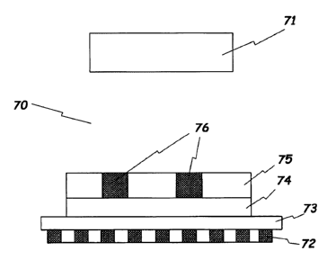
Referring to Fig. 4, there is shown an process room in which a test strip is
formed by sputtering with the help of a shadow mask. In this figure, a target
is
designated as reference numeral 71, a plurality of dot magnets as reference
numeral 72, an iron plate as reference numeral 73, an insulating substrate as
2 5 reference numeral 74, a shadow mask as reference numeral 75, and areas in
which
electrodes are to be formed as reference numeral 76. Upon sputtering, the mask
75 and the substrate 74 must be in close contact with each other. If there
exists a
gap therebetween, however small it is, the material to be deposited, e.g.,
gold,
penetrates the gap, thereby resulting in a collapsed pattern. In the present
3 0 invention, a plurality of dot magnets are employed to bring the shadow
mask into a
close contact with the insulating substrate 74. In this regard, if the shadow
mask
75 is thick, it cannot be affixed to the magnets owing to its own mass and
distortion. The experimental data obtained by the present inventors show that
a
preferable thickness of the shadow mask 75 falls into the range of 0.1 to 0.3
mm.
3 5 In accordance with the present invention, the magnets are preferably
arranged in an inverse dot pattern. That is, the iron plate 73 is placed on
the dot
CA 02368783 2001-09-26
WO 00/60340 PCT/KR00/00313
8
magnets 72. In this case, because the distortion of plasma hardly occurs, a
great
reduction can be brought about in the distance between the substrate 74 and
the
target 71, giving rise to a great increase in deposition efficiency.
Where plasma is generated, the process room is feasible to be heated to
the temperature at which commonly used plastic films are distorted. In this
case,
therefore, aluminum alloy, which shows high thermal transmission properties
and
paramagnetic properties, such as SUS 430, is used as the shadow mask.
Suitable for use in electrodes are noble metals. Examples of the noble
metals include palladium, platinum, gold, silver and so on by virtue of
superior
electrochemical properties in terms of stability on electrode surface regions,
electrochemical reproductivity, resistance to oxidation, etc. Particularly
preferable is gold which enjoys advantages of being relatively inexpensive,
simple
to process, superb in adhesiveness to plastic, and high in electrical
conductivity.
Although an electrode is formed of gold at as thin as 100 nm by sputtering, it
is
suitable as a disposable one because it has an electrically low resistance and
is
mechanically firmly affixed to an insulating substrate such as a plastic film.
Alternatively, rather than such noble metals only, metal materials which are
highly
adhesive to insulating substrates, such as plastics, and are inexpensive, may
be
used to form a primary electrode on which the noble metal is thinly covered,
for an
2 0 economical reason.
Returning to Fig. 3B, a reagent 56 reactive to analytes is affixed with a
suitable width across the two electrodes 52 and 54 on the insulating substrate
50.
The electrochemical biosensor test strip of the present invention can target a
broad
spectrum of analytes. Body materials, such as whole blood, blood serum, urine,
2 5 neurotransmitters and the like, as well as fermented or naturally
occurring
materials can be detected or measured by the electrochemical biosensor test
strip of
the present invention. The reagent 56 can be coated on the electrode area of
the
insulating substrate 50 with the aid of an automatic dispenser or by use of a
screen
printing, a roll coating, or a spin coating technique. When an electric
potential is
3 0 applied across the two electrodes after a sample is provided, the reagent
reacts with
the sample in a reaction time period to generate charges. Because these
charges,
which are generated through enzymatic reactions, relates to the concentration
of
the analyte of interest, the quantitative determination of the charges
provides
knowledge in regard to the concentration of the analyte.
3 5 Available as the reagent 56 are enzymes or redox mediators. A variety
of enzymes can be used in dependence on the analytes to be detected or
measured.
CA 02368783 2001-09-26
WO 00/60340 PCT/KR00/00313
9
For example, when glucose is to be detected or analyzed, glucose oxidase may
be
used. Useful redox mediators may be exemplified by potassium ferricyanide and
an imidazole osmium mediator which is disclosed in U. S. Pat. No. 5,437,999.
Besides enzymes and redox mediators, the reagent 56 may further comprise
buffers, hydrophilic macromolecules, surfactants, and/or film-forming agents.
During the reaction with a sample, a buffer in the reagent functions to keep a
pH
condition constant. On the other hand, the hydrophilic macromolecules are
useful
to fix other reagent components onto the electrode. Meanwhile, surfactants
facilitate the introduction of samples into a capillary space, which will be
explained later, by capillary action. Thus, the reagent for the detection or
measurement of glucose may comprise potassium ferricyanide, a potassium
phosphate buffer, cellulose, hydroxyethyl cellulose, a Triton X-100
surfactant,
sodium succinate, and glucose oxidase in combination. A detailed preparation
method of such reagents, and available enzymes and redox mediators can be
referred to U. S. Pat. No. 5,762,770.
With reference to Fig. 3C, an insulating plate 58 is fixed onto the
electrodes 52 and 54 and the insulating substrate by thermocompression bonding
or via a double-sided adhesive. Fig. 3D shows a profile of the structure of
Fig.
3C. As seen, the insulating plate 58 has a region to be in contact with the
2 0 electrodes 52 and 54 and the insulating substrate 50 and a protruded
region
corresponding to the area onto which the reagent 56 is affixed. Suitable as a
material for use in the insulating plate 58 may be the same as the material
for the
insulating substrate 50. Without being covered by the insulating plate 58, an
upper part of the insulating substrate 50 remains bared. The electrodes 52 and
54,
2 5 which are partially exposed at their upper parts, can serve as contact
pads through
which the electrochemical biosensor test strip, a meter and a power source are
electrically connected to one another.
As shown in Fig. 3D, the protruded region of the insulating plate 58, along
with the insulating substrate 50, forms a capillary space 64 which transverses
the
3 0 electrodes 52 and 54 in a widthwise direction. The capillary space needs
not be
completely as wide as, but may be wider or narrower than the reagent 56.
Likewise, the length of the capillary space also needs not be completely the
same
as, but may be greater or smaller than the width of the insulating substrate
50.
Only in order to reduce the error which occurs upon the introduction of a
sample
3 5 into the capillary space, the length of the capillary space preferably
agrees with the
width of the insulating substrate 50. The capillary space 64 thus formed is
where
CA 02368783 2001-09-26
WO 00/60340 PCT/KR00/00313
a sample such as blood is introduced. This introduction is facilitated by a
capillary action such that a precise determination can be done with even a
small
quantity of a sample.
Following is the principle of measuring the concentration of an analyte of
5 interest, that is, a matter to be detected and/or analyzed, by use of the
electrochemical biosensor test strip of the present invention. When a glucose
level in blood is assayed by use of a glucose oxidase with potassium
ferricyanide
as a redox mediator, for instance, the glucose is oxidized while the
ferricyanide is
reduced into ferrocyanide, both being catalyzed by the glucose oxidase. After
a
10 predetermined period of time, when an electrical potential from a power
source is
applied across the two electrodes, a current is passed by the electron
transfer
attributed to the re-oxidation of the ferrocyanide. The electrical potential
applied
across the two electrodes from a power source is suitably not more than 300 mV
and preferably on the order of around 100 mV when taking the properties of the
mediator into account.
By applying a stored algorithm to the current meter, the current thus
measured can be revealed as a dependent variable relative to the concentration
of
the analyte in the sample. In another mathematical method, by integrating the
current measured in a current-time curve against a certain period of time, the
total
2 0 quantity of charges generated during the time period can be obtained,
which is
directly proportional to the concentration of the analyte. In brief, the
concentration of an analyte in a sample can be quantitatively determined by
measuring the diffusing current which is generated by the enzymatic reaction-
based electrical oxidation of a redox mediator.
2 5 Now, turning to Fig. 5, there are stepwise illustrated processes of
fabricating electrodes by sputtering with the aid of a adhesive-type shadow
mask.
A plastic film 80 is provided onto which a plastic film 84 as a shadow
mask is attached via an adhesive layer 82, as shown in Fig. SA. The adhesive
layer 82 is in an interim attachment state to the plastic film 80, so they can
be
3 0 easily detached from each other.
Next, the plastic film 84 and the adhesive layer 82 are cut at
predetermined regions in the pattern of the electrodes to be formed, with the
aid of
a cutting plotter or an engraver, as shown in Fig. SB.
Subsequently, the cut regions are taken off, followed by vacuum
35 sputtering gold 88 wholly over the remaining structure to form electrodes
with the
plastic film 84 being used as a shadow mask, as shown in Fig. SC.
CA 02368783 2001-09-26
WO 00/60340 PCT/KR00/00313
11
Finally, the remaining plastic film 84 and adhesive layer 82 are removed
to bare the electrodes, as shown in Fig. SD.
Like this case, an adhesive-type shadow mask allows patterns to be
formed to the extent of the processing limit of a cutting plotter. Also, in
contrast
to typical iron shadow masks, such an adhesive-type shadow mask is flexible
and
attached to the film on which electrodes are to be formed, so that precise
patterns
can be established by sputtering without lateral diffusion.
Referring to Fig. 6, the method according to the present invention is
applied for the fabrication of an electrochemical biosensor test strip.
First, there is provided a plastic substrate 90 on which a structure of an
electrode strip is to be constructed, as shown in Fig. 6A.
Thereafter, a groove 92 is formed in a widthwise direction on the plastic
substrate 92, as shown in Fig. 6B. In this regard, it is preferred that both
side
banks 93 of the groove are slightly slanted lest gold electrodes, as will be
deposited
later, should be cut at their edges. For the formation of the groove 92, a
pressing
or a vacuum molding method may be used to emboss the surface of the plastic
substrate 90. Alternatively, the groove 92 can be formed by use of an
engraver.
The latter method is adapted to form the groove 92 of Fig. 6B. Since the
matter
for the plastic film 90 is usually wound around a roll, an engraver is more
2 0 preferably used to groove the plastim film in light of mass production.
This
procedure enables only two sheets of plastic film to be formed into an
electrochemical biosensor test strip which has a capillary space built-in,
without
additionally using a spacer as in U. S. Pat. No. 5,437,999.
Afterwards, electrode strips 94 and 95 are formed, as shown in Fig. 6C.
2 5 For this, gold is vacuum sputtered onto the plastic substrate 90 with the
aid of a
shadow mask, as previously mentioned. A reagent 98 is coated within the groove
92 across the working electrode and the reference electrode and dried, as
shown in
Fig. 6D.
For the purpose of establishing such a three-dimensional structure of an
3 0 electrode strip as shown in Fig. 6C, the adoption of a planar shadow mask
onto the
grooved substrate makes a gap as high as the capillary tube between the mask
and
the substrate, through which gold from the target 71 penetrates, resulting in
the
formation of dull-defined patterns. To avoid this problem, the following three
techniques are employed. First, the shadow mask is constructed so crookedly
that
35 it fits to the groove shape. By virtue of superb processability, SUS 430
can be
formed into such a three-dimensional structure of the shadow mask. Another
CA 02368783 2001-09-26
WO 00/60340 PCT/KR00/00313
12
solution is to control process parameters or the structure of the process
room.
The lower the pressure of the process room, the longer the mean free path of
the
gold atoms sputtered. Thus, the atoms incident in the perpendicular direction
onto the substrate become dense in number. In other words, fewer atoms run in
the lateral direction, resulting in the more precise definition of electrodes.
In
addition, lengthening the distance between the target 71 and the substrate 74
makes
a net flux of sputtered atoms perpendicular to the substrate 74. Where a five-
inch
circular target is employed, for example, almost no spread patterning is found
if
the distance from the substrate is over 7 cm. The last measure the present
invention takes to overcome the dull definition of electrode patterns is use
of a
collimator to block the atoms from running in a lateral direction. In contrast
to a
honeystructure of collimators, usually used in semiconductor processes, the
collimator used in the present invention is of a blind pattern because it can
restrict
the running of atoms only in a lateral direction.
Finally, an insulating plate 96 is bonded onto the plastic substrate 90 in
such a way that a major portion of the plastic substrate 90, including the
groove 92,
is covered with the insulating plate 96 while the other upper part remains
uncovered, as shown in Fig. 6E. In result, the groove forms a capillary space,
along with the insulating plate 96. Through the capillary space, a sample such
as
2 0 blood is introduced into the electrochemical biosensor test strip. A
profile of the
finished electrochemical biosensor test strip of Fig, 6E is shown in Fig. 6F
with an
exaggerated illustration of the capillary space 99.
INDUSTRIAL APPLICABILITY
As described hereinbefore, the test strip of the present invention is capable
of precise quantitative determination of analytes of interest by virtue of its
firm
fixation of appropriate reagents in a certain pattern and of its possessing of
a
maximal effective area of an electrode to detect charges.
3 0 In addition, the method for fabricating such a test strip according to the
present invention thin electrode is economically favorable owing to use of the
thin
electrode films and gives contribution to the precise detection of analytes by
forming an electrode of a uniform surface from gold, which is chemically
stable.
The present invention has been described in an illustrative manner, and it
is to be understood that the terminology used is intended to be in the nature
of
description rather than of limitation. Many modifications and variations of
the
CA 02368783 2001-09-26
WO 00/60340 PCT/KR00/00313
13
present invention are possible in light of the above teachings. Therefore, it
is to
be understood that within the scope of the appended claims, the invention may
be
practiced otherwise than as specifically described.