Note: Descriptions are shown in the official language in which they were submitted.
CA 02368857 2001-10-02
WO 00/60313 PCT/US00/08602
LOGISTICS SYSTEM AND METHOD WITH POSITION CONTROL
Background of the Invention
1. Field of the Invention
The present invention relates generally to the field of logistics, and more
particularly to a GPS-based system for controlling logistics in connection
with a
vehicle.
2. Description of the Prior Art
The field of logistics management is relatively broad and includes a wide
range of systems for tracking, controlling and reporting logistics operations
involving
various types of materials. For example, loading and unloading materials are
important logistics operations in the transportation field.
Automation is a primary goal of many logistics management systems. The
commercial availability of computer hardware and software for logistics
applications
has led to a relatively high degree of automation. For example, computerized
systems
are available for controlling material loading and unloading operations.
The global positioning system (GPS) is a significant recent development in the
field of vehicle navigation. GPS-based navigation systems are in widespread
use,
particularly in commercial vehicles. Current, state-of-the-art, GPS-based
navigation
systems provide positioning information with a relatively high degree of
accuracy.
Global position coordinates accurate to within a few centimeters can be
obtained with
current, commercially-available equipment.
The present invention applies the precise positioning features of current GPS
equipment to the logistics management field, and more particularly to material
loading and unloading operations. Heretofore there has not been available a
GPS-
based logistics system and method with the advantages and features of the
present
invention.
Summary of the Invention
In the practice of the present invention, a logistics system is provided for a
vehicle, such as a railcar. The disclosed embodiment of the logistics system
includes
a position control subsystem mounted on board the vehicle, an hydraulic
actuator
CA 02368857 2001-10-02
WO 00/60313 PCT/US00/08602
2
subsystem, a ballast discharge mechanism, and the global positioning system
(GPS).
The position control subsystem includes a microprocessor which associates
positioning data (e.g., GPS coordinates) for the vehicle with specific
logistics
operations, such as material loading and unloading. A control interface is
provided
for decoding signals from the microprocessor and for addressing them to
respective
components of the actuator subsystem for operating same. In the ballast
railcar
embodiment of the invention as shown, hopper doors are opened and closed to
direct
the flow of ballast therefrom onto a rail track. In the practice of the method
of the
present invention, the GPS is used for determining vehicle position. A
logistics
operation is perfonned at a predetermined location.
CA 02368857 2001-10-02
WO 00/60313 PCT/US00/08602
3
Objects and Advantages of the Invention
The principal objects and advantages of the present invention include:
providing a logistics management system and method; providing such a system
and
method which utilize the global positioning system (GPS); providing such a
system
and method which are adaptable to various vehicles; providing such a system
and
method which are adapted for use in conjunction with material loading and
unloading
operations; providing such a system and method which are adapted for
controlling
material discharge from railcars; providing such a system and method which are
adapted to utilize vehicle movement for positioning purposes; providing such a
system and method which are adapted for use with various positioning systems;
providing such a system and method which utilize commercially available GPS
equipment; providing such a system and method which utilize a computer mounted
on
board a vehicle for logistics management; providing such a system and method
which
can reduce the labor required for logistics operations; providing such a
system and
method which can be retrofit on existing vehicles; providing such a system and
method which can be installed on new vehicles; providing such a system and
method
which are adaptable for use with various discharge control means in connection
with
unloading operations; providing such a system and method which include data
storage
means and steps for storing data for use in conjunction with logistics
operations; and
providing such a system and method which are economical and efficient.
Other objects and advantages of this invention will become apparent from the
following description taken in conjunction with the accompanying drawings
wherein
are set forth, by way of illustration and example, certain embodiments of this
invention.
The drawings constitute a part of this specification and include exemplary
embodiments of the present invention and illustrate various objects and
features
thereof.
Brief Description of the Drawings
Fig. 1 is a schematic view of a logistics system with GPS positioning control
embodying the present invention, shown installed on a railcar for controlling
the
loading and unloading operations of same.
CA 02368857 2001-10-02
WO 00/60313 PCT/USOO/08602
4
Fig. 2 is a schematic diagram of an hydraulic actuating system for hopper door
assemblies on the railcar and a position control subsystem.
Fig. 3 is a perspective view of a railcar with a ballast discharge mechanism
controlled by the logistics system and method.
Fig. 4 is an enlarged, fragmentary, lower perspective view of the ballast
discharge mechanism, particularly showing a hopper door assembly thereof.
Fig. 5 is a schematic diagram of a logistics system comprising a first
modified
embodiment of the present invention with an alternative positioning control
subsystem.
CA 02368857 2001-10-02
WO 00/60313 PCT/US00/08602
Detailed Description of the Preferred Embodiments
5 I. Introduction and Environment
As required, detailed embodiments of the present invention are disclosed
herein; however, it is to be understood that the disclosed embodiments are
merely
exemplary of the invention, which may be embodied in various forms. Therefore,
specific structural and functional details disclosed herein are not to be
interpreted as
limiting, but merely as a basis for the claims and as a representative basis
for teaching
one skilled in the art to variously employ the present invention in virtually
any
appropriately detailed structure.
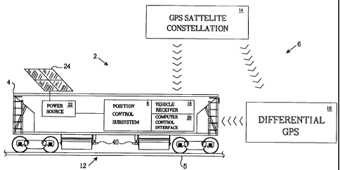
Referring to the drawings in more detail, the reference numeral 2 generally
designates a logistics system embodying the present invention. Without
limitation on
the generality of useful applications of a logistics system 2, it is shown
installed on a
railcar 4 for controlling unloading operations thereof.
The logistics system 2 generally comprises the global positioning system
(GPS) 6, an on-board position control subsystem 8, an hydraulic actuator
subsystem
10 and a ballast discharge mechanism 12.
II. GPS 6.
The GPS 6 (Fig. 1) includes a satellite constellation 14 comprising a number
of individual satellites whose positions are continuously monitored. The
satellites
transmit signals, including positioning data, which can be received by
differential
GPS stations 16 located in fixed positions and by GPS receivers, such as the
on-board
vehicle receiver 18, which are typically mobile. Various other configurations
and
arrangements of the GPS can be employed with the present invention. The
differential GPS station 16 receives signals from the satellite constellation
14 and
transmits signals to mobile GPS receivers.
III. On-Board Position Control Subsvstem 8.
The on-board position control subsystem 8 (Fig. 2) is mounted on the railcar
and includes the GPS vehicle receiver 18, which receives position data signals
(e.g.,
GPS coordinates) from both the satellite constellation 14 and the differential
GPS 16.
The vehicle receiver 18 can comprise any of a number of suitable, commercially-
CA 02368857 2001-10-02
WO 00/60313 PCT/USOO/08602
6
available, mobile receiver units. The vehicle receiver 18 is connected to a
microprocessor-based control interface/computer 20 which receives positioning
data
signals from the vehicle receiver 18, processes same and interfaces with the
actuator
subsystem 10. The control interface 20 can include any suitable microprocessor
and
preferably can be programmed to store data relating to logistics operations in
response
to GPS signals.
The control interface 20 includes a decoder 21 with inputs connected to the
microprocessor for receiving command signals addressed to specific piston-and-
cylinder units 32 in the actuator subsystem 10. The output of the decoder 21
is input
to a relay bank 26 with multiple relays corresponding to and connected to
respective
components of the hydraulic actuator subsystem 10. The position control
subsystem 8
is connected to a suitable, on-board electrical power source 22, which can
utilize a
solar photovoltaic collector panel 24 for charging or supplementing same.
IV. Hydraulic Actuator Subsystem.
The hydraulic actuator subsystem 10 (Fig. 2) includes multiple solenoids 28
each connected to and actuated by a respective relay of the relay bank 26.
Each
solenoid 28 operates a respective hydraulic valve 30. The valves 30 are
shifted
between extend and retract positions by the solenoids 28 whereby pressurized
hydraulic fluid is directed to piston-and-cylinder units 32 for respectively
extending
and retracting same. The piston and cylinder units 32 can comprise two-way
hydraulic units, pneumatic units or any other suitable actuators. An hydraulic
fluid
reservoir 34 is connected to the valves 30 through a suitable motorized pump
36 and a
pressure control 38.
V. Ballast Discharge Mechanism 12.
The ballast discharge mechanism 12 includes four hopper door assemblies 40
installed on the underside of the railcar 4 and arranged two to each side. The
hopper
door assemblies 40 discharge the railcar contents laterally and are adapted to
direct the
discharge inwardly (i.e. towards the center of a rail track 5) or outwardly
(i.e. towards
the outer edges of the rail track 5). The construction and function of the
hopper door
assemblies 40 are disclosed in the Bounds U.S. Patent No. 5,657,700, which is
CA 02368857 2001-10-02
WO 00/60313 PCT/US00/08602
7
incorporated herein by reference. As shown in Fig. 4, each hopper door
assembly is
operated by a respective piston-and-cylinder unit 32 for selectively directing
the flow
of ballast therefrom.
VI. Method of Operation.
In the practice of the method of the present invention, the on-board position
control subsystem 8 is preprogrammed with various data corresponding to the
operation of the logistic system 2. For example, discharge operations of the
ballast
discharge mechanism 12 can be programmed to occur at particular locations.
Thus,
ballast can be applied to a particular section of rail track 5 by inputting
its GPS
coordinates and programming the position control subsystem 8 to open the
hopper
door assemblies 40 in the desired directions and for predetermined durations.
The
GPS signals received by the on-board position control subsystem 8 can provide
relatively precise information concerning the position of the railcar 4.
VII. First Modified Embodiment Logistics System and Method 102.
The reference numeral 102 generally designates a logistics system 102
comprising a first modified embodiment of the present invention with a linear
movement-based position control subsystem 104. The position control subsystem
104
can comprise any suitable means for measuring the travel of a vehicle, such as
the
railcar 4, and/or detecting its position along the rail track 5 or some other
travel path.
The position control system 104 includes a computer 106 which interfaces
with an optional rough position detector 108 for detecting rough position
markers 110.
For example, the rough position markers 110 can be located alongside the rail
track 5
whereby the rough position detector 108 provides a signal to the computer 106
when
the railcar 4 is positioned in proximity to a respective rough position marker
110. The
position control subsystem 104 can also include a suitable linear distance
measuring
device for measuring travel. For example, an encoder/counter 112 can be
mounted on
the railcar 4 for measuring distances traveled by same or for counting
revolutions of a
railcar wheel 14. The encoder/counter 112 can be connected to a travel
distance
converter 116 which provides signals corresponding to travel distances to the
CA 02368857 2001-10-02
WO 00/60313 PCT/USOO/08602
8
computer 106. The computer 106 can interface with an hydraulic actuator
subsystem
10 such as that described above.
It is to be understood that while certain forms of the present invention have
been illustrated and described herein, it is not to be limited to the specific
forms or
arrangement of parts described and shown.