Note: Descriptions are shown in the official language in which they were submitted.
CA 02369586 2002-O1-29
CONTROL APPARATUS FOR HYBRID VEHICLE
BACKGROUND OF THE INVENTION
Field of the Invention
~'S~ //~ %
The present invention relates to a control apparatus for a hybrid vehicle, and
in
particular, relates to a control apparatus for a hybrid vehicle that can
improve fuel
consumption by a cylinder deactivated operation of an engine under certain
conditions.
Description of the Related Art
Conventionally, hybrid vehicles having an engine and a motor as a drive source
for a vehicle are known. One type of such a hybrid vehicles is a parallel
hybrid vehicle
in which the drive output from the engine is assisted by the motor.
In the parallel hybrid vehicle, at the time of acceleration the driving power
output
from the engine is assisted by the motor, while at the time of deceleration,
various
control is carried out such as performing battery charging by deceleration
regeneration,
so that the remaining charge (electrical energy) of the battery can be
increased while
satisfying the requirements of the driver. Furthermore, since the structural
mechanism is
such that the engine and the motor are arranged in series, the structure can
be simplified,
and the whole system can be reduced to a low weight. Therefore, there is an
advantage
in that there is a high degree of freedom in vehicle assembly .
In order to eliminate the influence of engine friction (engine braking) at the
time
of deceleration regeneration; several mechanisms have been proposed for the
aforementioned parallel hybrid vehicle, such as a mechanism which includes a
clutch
CA 02369586 2002-O1-29
2
between the engine and motor (for example, refer to Japanese Unexamined Patent
Application; First Publication No. 2000-97068) or the engine, motor and
transmission
are connected in series (for example, refer to Japanese Unexamined Patent
Application,
First Publication No. 2000-125405) in order to achieve maximum simplification.
However, in the former mechanism comprising a clutch between the engine and
motor, have drawbacks in that the structure becomes complicated by inserting
the clutch
and the assembly capability of the vehicle is reduced so that insertion of the
clutch
reduces transmission efficiency of the power transmission system. On the other
hand, in
the latter construction in which the engine, motor and transmission are
connected in
series, since the regeneration energy is reduced by the aforementioned
friction of the
engine, the electrical energy that could be conserved by regeneration is
reduced.
Therefore, there is a problem in that the assist amount by the motor is
limited.
A measure to reduce the friction loss during deceleration is proposed to
control
the throttle valve in the opening side in the deceleration mode of the vehicle
by
employing an electronic controlled throttle mechanism for sharply reducing the
pumping
losses and for increasing the deceleration regeneration. However, since a
large amount
of fresh air normally flows into the exhaust system, it reduces the
temperature of the
catalyst and an A/F (air/fuel) sensor, so that the optimum control of the
exhaust gas is
degraded.
SUMMARY OF THE INVENTION
Therefore, the present invention provides a control apparatus of a hybrid
vehicle,
capable of remarkably increasing the amount of regeneration without hurting
the
optimum control of the exhaust gas so that the fuel consumption can be
improved to a
large extent by the motor assist.
CA 02369586 2002-O1-29
To solve the above-described problems, a first aspect of the invention
provides a
control apparatus for a hybrid vehicle having an engine (for example, engine E
in the
embodiment) and a motor (for example, motor M in the embodiment) as the drive
source,
wherein a fuel supply to the engine is stopped by a fuel supply stop device
(for example,
step 5212 in the embodiment) at the time of deceleration, and performs
regenerative
braking by the motor depending on the deceleration state, wherein the engine
is a type of
engine capable of executing the all cylinders deactivated operation, and the
control
device comprises a cylinder deactivated operation determination device (for
example, an
all cylinders deactivated operation execution flag F ALCS in the embodiment)
for
determining whether the cylinders should be deactivated depending on the
nu~ning
conditions of the vehicle, and a cylinder deactivated operation execution
device (for
example, variable valve timing mechanism VT in the embodiment) for executing
the all
cylinders deactivated operation of the engine when cylinder deactivated
operation is
determined by the cylinder deactivated operation determination device, and
when the
fuel supply to the engine is stopped by the fuel supply stop device during
deceleration,
the cylinders are deactivaxed based on the cylinder deactivated operation
determination
device and the cylinder deactivated operation execution device.
By constituting the control apparatus of a hybrid vehicle as described above,
while fuel supply to the engine is stopped by the fuel supply stop device, if
the cylinder
deactivated operation determination device determines to execute the cylinder
deactivated operation, it becomes possible to execute the cylinders
deactivated operation
of the engine by the cylinder deactivated operation execution device.
According to the second aspect of the present invention, the control apparatus
comprises a cylinder deactivated operation detecting device (for example, all
cylinders
deactivated operation solenoid flag F ALCSSOL) for detecting the operation or
non-
CA 02369586 2002-O1-29
4
operation of the cylinder deactivated operation execution device, and when the
cylinder
deactivated operation determination device determines that the cylinder
deactivated
operation is released, and the cylinder deactivated operation detecting device
detects an
inoperative state of the cylinder deactivated operation execution device, the
fuel supply
stop to the engine by the fuel supply stop device is released.
By constituting the control apparatus of a hybrid vehicle as described above
in
the second aspect, when the cylinder deactivated operation determination
device
determines that the cylinder deactivated operation is released, and the
cylinder
deactivated operation detecting device detects an inoperative state of the
cylinder
deactivated operation execution device, the fuel supply stop to the engine by
the fuel
supply stop device is released, so that fuel supply can be restarted.
According to the third aspect of the present invention, the cylinder
deactivated
operation execution device closes both the intake valves (for example, intake
valve 1V in
the embodiment) and exhaust valves (for example, exhaust valve EV in the
embodiment)
of the cylinders.
By constituting the control apparatus of a hybrid vehicle as described above
in
the third aspect, when the cylinders enters into the deactivated operation,
engine
pumping losses and friction are reduced, and it is possible to prevent fresh
air from
flowing into the exhaust system.
According to the fourth aspect of the invention, when fuel supply is restarted
by
releasing the fuel supply stop to the engine by the fuel supply stop device,
fuel is
gradually increased to a predetermined amount (for example, an incremental
amount
DKAALCS in the embodiment) depending on the degree of the throttle opening
(for
example, throttle opening TH).
CA 02369586 2005-02-28
By constituting the control apparatus of a hybrid vehicle as described above
in the
fourth aspect, when fuel supply is restarted by releasing the fuel supply stop
to the engine
by the fuel supply stop device, it is possible to prevent the fuel supply
amount from
increasing rapidly.
According to an aspect of the present invention there is provided a control
apparatus for a hybrid vehicle comprising a driving power source composed of
an engine
and a motor, wherein fuel supply to the engine is stopped by a fuel supply
stop device
during deceleration, and the motor generates regenerative power during
deceleration
depending on a deceleration state; wherein the engine is a type of engine
capable of
executing a cylinder deactivated operation for at least one cylinder, the
control apparatus
comprising a cylinder deactivated operation determination device for
determining
whether it is appropriate for the engine to enter a cylinder deactivated
operation
depending on driving conditions of the vehicle, and a cylinder deactivated
operation
execution device for executing the cylinder deactivated operation of the
engine when the
cylinder deactivated operation is determined by the cylinder deactivated
operation
determination device, wherein when the fuel supply to the engine is topped by
the fuel
supply stop device during deceleration, the at least one cylinder is
deactivated based on
the cylinder deactivated operation determination device and the cylinder
deactivated
operation execution device closes both intake valves and exhaust valves of the
cylinders,
wherein the control apparatus further comprises a cylinder deactivated
operation
detecting device for detecting operation or non-operation of the cylinder
deactivated
operation execution device; and when the cylinder deactivated operation
determination
device determines that the cylinder deactivated operation is released, and the
cylinder
deactivated operation detecting device detects an inoperative state of the
cylinder
deactivated operation execution device, fuel supply stop to the engine by the
fuel supply
CA 02369586 2005-02-28
Sa
stop device is released, wherein the control apparatus further comprises a
variable valve
timing mechanism for changing timing to close or open the intake and exhaust
valves,
and when the cylinder deactivated operation determination device determines
that it is
appropriate for the engine to enter a cylinder deactivated operation, fuel
supply to the
engine is stopped first, and the cylinder deactivated operation execution
device then
closes both the intake valves and the exhaust valves of the at Least one
cylinder for
executing the cylinder deactivation operation, and, when the cylinder
deactivated
operation determination device determines that the cylinder deactivated
operation is
released, a variable timing mechanism changes timing to open both the intake
valves and
the exhaust valves of the at least one cylinder first, and the fuel supply is
then restarted in
order to absorb shock when resuming the fuel supply and switching from the
cylinder
deactivated operation to normal operation.
BRIEF DESCRIPTION OF THE DRAWINGS
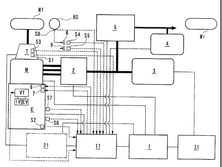
Fig. I is a block diagram showing a parallel hybrid vehicle according to one
embodiment of the present invention.
Fig. 2 is a front view of a variable valve timing mechanism of the embodiment
of
the present invention.
Fig. 3 shows the variable valve timing mechanism of the embodiment of the
present invention. Fig. 3A is a sectional view of the main parts of the
variable valve
timing mechanism in an all cylinders normal operation state, and 3B is a
sectional view
of the main parts of the variable valve timing mechanism in an all cylinders
deactivated
operation state.
Fig. 4 is a flow chart showing an MA (motor) basic mode of the embodiment of
the present invention.
CA 02369586 2005-02-28
Sb
Fig. 5 is a flow chart showing the MA (motor) basic mode of the embodiment of
the present invention.
Fig. 6 is a flow chart showing all cylinders deactivated operation switching
execution processing of the embodiment of the present invention.
Fig. 7 is a flow chart showing all cylinders deactivated operation previous
condition execution determination processing of the embodiment of the present
invention.
CA 02369586 2002-O1-29
6
Fig. 8 is a flow chart showing all cylinders deactivated operation release
condition determination processing of the embodiment of the present invention.
Fig. 9 is a flow chart showing fuel cut execution determination processing of
the
embodiment of the present invention.
Fig. 10 is a flow chart showing an fuel gradual incremental fuel addition
coefficient computation processing when restarting the fuel supply according
to one
embodiment of the present invention.
Fig. 11 is a graph showing the relationship between throttle opening TH and
incremental amount #DKAALCS.
Fig. 12 is a timing diagram of the embodiment of the present invention.
DETAILED DESCRIPTION OF THE INVENTION
Hereinafter; embodiments of the present invention are described with reference
to the attached drawings.
Fig. 1 shows a parallel hybrid vehicle of an embodiment of the present
invention,
in which an engine E, a motor M and a transmission T are connected in series.
The
driving forces from both the engine E and the motor M are transmitted to front
wheels
Wf serving as drive wheels via the transmission T comprising either an
automatic
transmission or a manual transmission. Furthermore, when a driving force is
transmitted
to the motor M side from the front wheels Wf, at the time of deceleration of
the hybrid
vehicle, the motor M functions as a generator to produce so called
regenerative braking,
and the kinetic energy of the vehicle is recovered as electrical energy. The
rear wheels
are designated as Wr.
The drive and regenerative braking of the motor M are controlled by a power
drive unit 2, which receives control instructions from the motor ECU 1. A
battery 3 of a
CA 02369586 2002-O1-29
7
high-tension system for transfernng electrical energy to and from the motor M
is
connected to the power drive unit 2. The battery 3 is constructed from
individual
modules wherein, for example, a plurality of cells is connected in series,
with a plurality
of these modules connected in series. Mounted on the hybrid vehicle is a 12
volt
auxiliary battery 4 for driving various auxiliary equipment. This auxiliary
battery 4 is
connected to the battery 3 via a down converter 5. The down converter 5, which
is
controlled by the FIECU I l, reduces the voltage of the battery 3 to charge
the auxiliary
battery 4.
The FIECU 1 l, in addition to the motor ECU 1 and the down converter 5,
controls the operation of a fuel supply amount control device 6 for
controlling the
amount of fuel supplied to the engine E, the operation of a starter motor 7,
and also the
ignition timing. Therefore, inputs to the FIECU 11 are: a signal from a speed
sensor S 1
for detecting the speed V based on the speed of rotation of a drive shaft in
the
transmission T, a signal from an engine rotation speed sensor S2 for detecting
engine
rotation speed NE, a signal from a gear shift position sensor S3 for detecting
the shift
position of the transmission T, a signal from a brake switch S4 for detecting
the
operation of a brake pedal 8, a signal from a clutch switch SS for detecting
the operation
of a clutch pedal 9, a signal from a throttle opening sensor S6 for measuring
the throttle
opening TH, and a signal from an inlet pipe negative pressure sensor S7 for
detecting
inlet pipe negative pressure PBGA. Numeral 31 denotes a battery ECU that
protects the
battery 3, and computes the remaining charge QBAT of the battery 3. Here, in
the case
of a CVT vehicle , a CVT control CVTECU 21 is installed as shown by broken
lines in
Fig. 1.
CA 02369586 2002-O1-29
8
BS denotes a brake servo connected to a brake pedal 8, and a negative pressure
sensor S8 for detecting the master power internal negative pressure (MPGA) of
the
brake is installed in this brake servo BS.
This negative pressure sensor S8 is connected to an engine ECU 11.
Here, the abovementioned engine E is a type of engine capable of switching
between all cylinders operating (normal operation) in which all cylinders
operate, and
all cylinders deactivated operation, in which all cylinders are deactivated.
As shown in
Fig. 1, typically the intake valve IV and exhaust valve EV of each cylinder of
the engine
E are constructed such that their operation can be deactivated by a variable
valve timing
system VT (cylinder deactivated operation execution device). Here, the
variable valve
timing system VT is connected to the engine ECU 11.
A specific description will be given using Fig. 2 and Fig. 3.
Fig. 2 shows an example in which a variable valve timing system VT for all
cylinders deactivated operation is applied in a SOHC type engine. An intake
valve IV
and an exhaust valve EV are installed in a cylinder, which is not shown in the
figure, and
the intake valve IV and exhaust valve EV are mounted at an angle such thax the
intake
and exhaust ports, which are not shown in the figure, are closed by valve
springs 51.
Also, numeral 52 denotes a lift cam installed on a cam shaft 53. Intake valve
and
exhaust valve cam lift rocker arms 54a and 54b are linked to this lift cam 52,
mounted so
as to rotate via intake valve and exhaust valve rocker arm shafts 53a and 53b.
Furthermore, valve drive rocker arms SSa and SSb are rotatably mounted on each
of the rocker arm shafts 53a and 53b, adjacent to the cam lift rocker arms 54a
and 54b.
The moving ends of the rotatable valve drive rocker arms SSa and SSb press the
top ends
of the intake valve IV and the exhaust valve EV in order to operate the
opening of the
intake valve IV and the exhaust valve EV. Here, the base ends (opposite ends
from the
CA 02369586 2002-O1-29
9
valve interface) of the valve drive rocker arms SSa and SSb are constructed
such that
they are able to slide on a perfect circle cam 531 installed on the cam shaft
53.
Fig. 3 shows the cam lift rocker arm 54b and the valve drive rocker arm SSb
using the exhaust valve as an example.
In Fig. 3 (a) and Fig. 3 (b), an oil pressure chamber 56 is formed on the
opposite
side from the lift cam 52, with the exhaust valve rocker arm shaft 53b in the
center, in
the cam lift rocker arm 54b and the valve drive rocker arm SSb, which extends
over both
the cam lift rocker arm 54b and the valve drive rocker arm SSb. Inside the oil
pressure
chamber 56, pins 57a and 57b are installed such that these can slide freely.
These pin
57a and 57b is urged toward the cam lift rocker arm 54b side via a pin spring
58.
Furthermore, an oil pressure supply path 59 is formed inside the exhaust valve
rocker arm shaft 53b. This oil pressure supply path 59 is communicated with
the oil
pressure chamber 56 via an opening 60 of the oil pressure supply path 59 and a
communication path 61 of the cam lift rocker arm 54b. Working fluid is
supplied from
an oil pump P to the oil pressure supply path 59 by switching a spool valve
SV. The
solenoid of this spool valve SV is connected to the engine ECU 11.
Here, in a case where oil pressure is not applied from the oil pressure supply
path
59, as shown in Fig. 3A, pins 57a and 57b are positioned by the pin spring 58
such that it
extends between the cam lift rocker arm 54b and the valve drive rocker arm
SSb. On the
other hand, if oil pressure is applied from the oil supply path 59 by a
cylinder
deactivated operation signal, as shown in Fig. 3 (b), the pin 57 slides to the
valve drive
rocker arm SSb side against the pin spring 58, and releases the link between
the cam Lift
rocker arm 54b and the valve drive rocker arm SSb. Here, the intake valve has
the same
construction.
CA 02369586 2002-O1-29
I
Accordingly, when the conditions for all cylinders deactivated operation as
mentioned later are satisfied, oil pressure is applied from the oil pressure
supply path 59
to the oil pressure chamber 56 on both the intake valve and exhaust valve via
an oil
pressure supply device (not shown in the figure) by a signal from the engine
ECU 11.
Then, the pins 57 which had linked the cam lift rocker arms 54a and 54b and
the valve
drive rocker arms SSa and SSb, slide toward the valve drive rocker arms SSa
and SSb
sides, and the links between the cam lift rocker arms 54a and 54b and the
valve drive
rocker arms SSa and SSb are released.
As a result, the cam lift rocker arms 54a and 54b are driven by the rotary
movement of the lift cam 52. However, the valve drive rocker arms SSa and SSb,
whose
links with the cam lift rocker arms 54a and 54b by the pins 57 were released,
are not
driven by either the idle running perfect circle cam 537 or the cam lift
rocker arms 54a
and 54b, and hence they do not contribute to the opening of the valves IV and
EV. As a
result, the valves IV and EV remain closed, which enables the all cylinders
deactivated
operation .
[MA (Motor) Basic Modes)
Next is a description of the MA (motor) basic modes based on the flow charts
shown in Fig: 4 and Fig. 5. This processing is repeated at a predetermined
cycle time.
Here, the MA (motor) basic modes are: "idle mode", "idle stop mode",
"deceleration mode", "cruise mode" and "acceleration mode". In the idle mode,
fuel
supply is restarted after fuel cut to maintain the engine E in an idle
condition, and in the
idle stop mode, for example at the time the vehicle is stopped, the engine is
stopped in a
defined condition. Furthermore, in the deceleration mode, regenerative braking
by the
motor M is performed. In the acceleration mode, the engine E is assisted by
the motor
CA 02369586 2002-O1-29
11
M, and in the cruise mode, the motor M is not driven so that the vehicle runs
only by the
driving force of the engine E. In the abovementioned deceleration mode, an all
cylinders
deactivated operation is executed.
In step SOS 1 of Fig. 4, it is determined whether an MT/CVT determination flag
F
AT is "1". When the determination is "YES" (indicating a CVT vehicle), the
flow
proceeds to step 5060. When the determination is "NO" (indicating a MT
vehicle), the
flow proceeds to step 5052.
In step 5060, for CVT it is determined whether an in gear determination flag
F ATNP is "1". When the determination is "YES" (1V or P position), the flow
proceeds
to step 5083, and when the determination is "NO" (in gear), the flow proceeds
to step
S060A.
In step S060A, it is determined whether the gearshift is being operated (shift
position cannot be determined due to the gear shift being operated) by
determining
whether a switch back flag F VSWB is "1". When the determination is "YES"
(being
shifted), the flow proceeds to 5085, shifts to "idle mode", and terminates. In
idle mode,
the engine E is maintained in an idle state. When the determination of step
S060A is
"NO" (not being shifted), the flow proceeds to step S053A.
In step 5083, it is determined whether an engine stop control execution flag
F FCMG is "1", When the determination is "NO", the flow proceeds to the "idle
mode"
in step 5085, and the control ends. When the determination of step 5083 is
"YES", the
flow proceeds to step 5084, shifts to the "idle stop mode", and the control
terminates. In
the idle stop mode, for example at the time the vehicle is stopped, the engine
is stopped
in a defined condition.
In step 5052, it is determined whether a neutral position determination flag
F NSW is "1". When the determination is "YES" (neutral position), the flow
proceeds
CA 02369586 2002-O1-29
12
to step S083; and when the determination is "NO" (in gear), the flow proceeds
to step
S053.
In step 5053, it is determined whether a clutch engagement determination flag
F CLS W is "1 ". When the determination is "YES" (clutch is disengaged), the
flow
proceeds to step 5083, and when the determination is "NO" (clutch is engaged),
the flow
proceeds to step S053A.
In step S053A, it is determined whether the remaining battery charge QBAT is
greater than or equal to the low speed start determination remaining battery
charge
QBJAM. When the determination is "YES", the flow proceeds to step 5054, and
when
the determination is "NO", the flow proceeds to step S053B.
In step S053B, it is determined whether a low speed start determination flag
F JAMST is "1 ". This iow speed start determination flag F JAMST is a flag
whose
setting becomes "1" when a vehicle start at a low speed and runs slowly. When
the
determination of step S053B is "YES", the flow proceeds to step 5083. When the
determination of step S053B is "NO", the flow proceeds to. step 5054. This is
because,
when a vehicle has a low remaining battery charge and departs slowly, and
since it
means that there is no intention to accelerate, idle mode or idle stop mode
(generated
either by the idle mode or stopping the engine by the abovementioned engine
stop
determination) is preferable in order to protect the battery.
In step 5054, it is determined whether an idle determination flag F THIDLMG is
"I". When the determination is "NO" (fully closed), the flow proceeds to step
5061, and
when the determination is "YES" (not fully closed), the flow proceeds to step
S054A.
In step S054A, an engine rotation speed increase flag F NERGNUP at the time
of partially engaged clutch determination is set to "0", and the flow proceeds
to step
SO55. Here, this engine rotation speed increase flag F NERGNUP at the time of
CA 02369586 2002-O1-29
13
partially engaged clutch determination is described later. In step SOSS, it is
determined whether a motor assist determination flag F MAST is "1". This flag
judges
whether the engine is to be assisted by the motor M. In the case of "1 ", it
means that
assist is required, and in the case of "0", assist is not required. Here, the
assist trigger
determination processing sets the motor assist determination flag.
When the determination of step SOSS is "NO", the flow proceeds to step 5061.
When the determination of step SOSS is "YES", the flow proceeds to step SOS6.
In step 5061, it is determined whether the MT/CVT determination flag F AT is
"1". When the determination is "NO" (MT vehicle), the flow proceeds to step
5063, and
when the determination is "YES" (CVT vehicle), the flow proceeds to step 5062.
In step 5062, it is determined whether a reverse position determination flag
F ATPR is "1". When the determination is "YES" (reverse position), the flow
proceeds
to step S08S, and when the determination is "NO" (position other than
reverse), the flow
proceeds to step S063.
in step SOS6, it is determined whether the MTICVT determination flag F AT is
"1". When the determination is "YES" (CVT vehicle), the flow proceeds to step
SOS7,
aad when the determination is "NO" (MT vehicle), the flow proceeds to step
S067A.
In step SOS7, it is determined whether a brake ON determination flag F BKSW
is "1". When the determination is "YES" (brake ON), the flow proceeds to step
5063,
and when the determination is "NO" (brake OFF), the flow proceeds to step
SOS7A.
In step 5063, it is determined whether a vehicle speed VP is "0". When the
determination is "YES", the flow proceeds to step 5083, and when the
determination is
"NO", the flow proceeds to step S064.
CA 02369586 2002-O1-29
14
In step S064, it is determined whether the engine stop control execution flag
F,FCMG is "1". When the determination is "NO", the flow proceeds to step 5065,
and
when the determination is "YES", the flow proceeds to step 5084.
In step S065, it is determined whether a shift change forced REGEN release
determination processing delay timer TNERGN is "0". When the determination is
"YES", the flow proceeds to step S066, and when the determination is "NO", the
flow
proceeds to step 5068.
In step 5066, it is determined whether the rate of change of engine rotation
speed
DNE is less than the negative value of a DNE REGEN cut determination engine
rotation
speed #DNRGNCUT. Here, the DNE REGEN cut determination engine rotation speed
#DNRGNCUT is the rate of change DNE of engine rotation speed NE which becomes
a
reference for determining whether the generation amount is to be subtracted,
depending
on the rate of change of engine rotation speed DNE.
When it is determined in step 5066 that the decrease (rate of fall) of the
engine
rotation speed NE is high (YES), the flow proceeds to step 5082. In step 5082,
the
engine rotation speed increase flag F NERGNUP for at the time of partially
engaged
clutch determination is set to "1 ", and the flow proceeds to step 5085.
This engine rotation speed increase flag F NERGNUP at the time of partially
engaged clutch is provided in order to prevent hunting of frequently switching
the
rotation speed NE in the determination in step S70, which will be mentioned
later, every
time when the engine rotation speed of the partially engaged clutch is
changed. The
engine rotation speed increase flag F NERGNUP for at the ime of partially
engaged
clutch determination is set in order to clarify this.
CA 02369586 2002-O1-29
When the determination of step S066 is that the engine rotation speed NE is
increasing (up), or the decrease (rate of fall) of the engine rotation speed
NE is low (no),
the flow proceeds to step 5067.
In step 5067, it is determined whether the MT/CVT flag F AT is "1". When the
determination is "NO" (MT vehicle), the flow proceeds to step S079, and when
the
determination is "YES" (CVT vehicle), the flow proceeds to step 5068.
In step 5079, it is determined whether a partially engaged clutch
determination
flag F NGRHCL is "1 ". When it is determined that the clutch is partially
engaged
(YES), the flow proceeds to step S082. In contrast, when it is determined that
the clutch
is not partially engaged (no), the flow proceeds to step S080.
In step 5080, the previous gear position NGR and the present gear position
NGRI are compared, and it is determined whether there has been a shift up by
comparison between the present and previous gear positions.
When the determination of step S080 is that the gear position has been shifted
up
(NO), the flow proceeds to step S082. When the determination of step S080 is
that the
gear position has not been shifted up between the previous and present times
(YES); the
flow proceeds to step S068. The reason that control shifts to step S082, and
afterwards
shifts to idle mode, in this manner when the clutch is partially engaged, is
that if
regeneration is performed in a partially engaged clutch state, there is a
possibility of
stalling the engine. Furthermore, the reason that the flow proceeds to step
S082, and
afterwards shifts to idle mode, in the case of shifting up, is that if
regeneration is
performed at the time of low engine rotation speed due to the shift up, there
is a
possibility of stalling the engine.
In step S068, it is determined whether the engine rotation speed increase flag
F NERGNUP for at the time that the partially engaged clutch determination is
"1 ".
CA 02369586 2002-O1-29
16
When the determination is that an increase in engine rotation speed is
required at the
time of partially engaged clutch and the flag is set (=1, YES); the flow
proceeds to step
5081, wherein a revolution speed increase #DNERGNUP for preventing hunting is
added to the charge engine rotation speed lower limit value #NERGNLx, which is
set for
each gear, this added value is set to the charge engine rotation speed lower
limit value
NERGNL, and the flow proceeds to step 5070. When the determination of step
SU68 is
that an increase in engine rotation speed is not required at the time of
partially engaged
clutch determination, and the flag is reset (~, NO), the flow proceeds to step
S069, and
the charge engine rotation sped lower limit value #NERGNLx, which is set for
each
gear, is set to the charge engine rotation speed lower limit value NERGNL, and
the flow
proceeds to step 5070.
Then, in step S070 it is determined whether the engine rotation speed NE is
less
than or equal to the charge engine rotation speed lower limit value NERGNL.
When the
determination is that it is rotating slowly (NE 5 NERGNL, YES ), the flow
proceeds to
step S082. When the determination is that the rotation speed is high (NE >
NERGNL,
no), the flowproceeds to step SO?l.
In step S057A, it is determined whether a scramble assist request flag
F MASTSCR is "I". This scramble assist is for improving the perceived feeling
of
acceleration by increasing the assist amount temporarily at the time of
acceleration:
Basically, when the rate of throttle change is high, the arrangement is such
that the
scramble assist request flag F MASTSCR is set to "1".
When the determination of step S057A is "NO", the acceleration REGEN
processing is performed in step S057B, and the flow proceeds to step S057D.
Furthermore, when the determination of step S057A is ''YES", subtraction
processing for
CA 02369586 2002-O1-29
i7
a final charge instruction value REGENF is performed instep S057C, and the
flow
proceeds to step S058.
In step S057D, it is determined whether an acceleration REGEN processing flag
F ACCRGN is "i ". When the determination is "YES" (processing has been
performed),
the flow proceeds to step 5058, and when the determination is "NO" (processing
has not
been performed), the flow proceeds to step S057C.
In step 5058, it is determined whether the final charge instruction value
REGENF is less than or equal to "0". When the determination is "YES", the flow
proceeds to "acceleration mode" in step S059. In acceleration mode, the engine
E is
assisted by the motor M, and the flow proceeds to step S059A. When the
determination
of step 5058 is "NO", the control ends.
In step S059A, it is determined whether an assist permit flag F ACCAST is "i
".
When the determination is "YES", the control ends, and when the determination
is "NO",
the flow proceeds to step S059B.
Instep S059B, it is determined whether a start assist permit flag F STRAST is
"1 ". When the determination is "YES", the control ends, and when the
determination is
"NO", the flow proceeds to step S059C.
In step S059C, it is determined whether a scramble assist permit flag F;SCRAST
is "1 ". When the determination is "YES", the control ends, and when the
determination
is "NO", the flow proceeds to step S059D.
In step S059D, it is determined whether a cylinder deactivation resumption
assist
permit flag F RCSAST is "i". When the determination is "YES", the control
ends, and
when the determination is "NO", the flow proceeds to step 5063. Here, when the
cylinder deactivated operation resumption assist permit flag F RCSAST is "1",
it means
CA 02369586 2002-O1-29
18
that an assist by the motor is permitted when shifting from the all cylinders
deactivated
operation to be described later to the all cylinder (normal) operation.
In step 5071, it is determined whether the vehicle speed VP is less than or
equal
to the deceleration mode brake determination lower vehicle speed limit
#VRGNBK.
Here, this deceleration mode brake determination lower vehicle speed limit
#VRGNBK
is a value with hysteresis. When the determination is that the vehicle speed
VP <_ the
deceleration mode brake deterniination lower vehicle speed limit #VRGNBK
(YES), the
flow proceeds to step 5074: When the determination in step 5071 is that the
vehicle
speed VP > the deceleration mode brake deterniination lower vehicle speed
limit
#VRGNBK (NO), the flow proceeds to step 5072.
In step 5072, it is determined whether a brake on determination flag F BKSW is
"1 ". When the determination is "YES", the flow proceeds to step 5073, and
when the
determination is "NO", the flow proceeds to step S074.
In step 5073, it is determined whether an idle deternunation flag F THIDLMG is
"1". When the determination is "NO" (throttle is fully closed), the flow
proceeds to
"deceleration mode" in step 5078, acceleration REGEN processing is performed
in step
S077A, and the control ends. Here; in deceleration mode, regenerative braking
(deceleration regeneration permit flag F DECRGN =1 ) is performed by the motor
M.
However, in deceleration mode, the all cylinders are deactivated, so that the
amount of
regeneration by the motor M can be increased by the amount that engine
friction is
reduced. When the determination of step 5073 is "YES" (throttle is not fully
closed), the
flow proceeds to step 5074.
In step 5074, it is determined whether a fuel cut flag F FC is "1 ". This flag
is a
fuel cut determination flag, which becomes "1" when regeneration by the motor
M is
performed in "deceleration mode" in step S078, and cuts the fuel. If the
result of the
CA 02369586 2002-O1-29
19
determination in step S074 is that deceleration fuel cut is in effect (YES),
the flow
proceeds to step S078. If the result of the determination in step 5074 is that
fuel cut is
not in effect (NO), the flow proceeds to step 5075, where the final assist
instruction
value ASTPWItF is subtracted, and then proceeds to step 5076:
In step 5076, it is determined whether the final assist instruction value
ASTPW1ZF is less than or equal to "0". When the determination is "YES", the
control
shifts to the "cruise mode" in step 5077, acceleration HEGEN processing is
performed in
step S077A, and the control ends. In the cruise mode, the motor M is not
driven and the
vehicle runs under the driving force of the engine E. Furthermore, the battery
3 may be
charged by regenerative operation of the motor M or by using the motor as a
generator
depending on the running conditions of the vehicle.
When the determination of step S076 is "NO", the control ends.
[All Cylinders Deactivated Operation Switching Execution Processing]
Next, an all cylinders deactivated operation switching execution processing
based on Fig. 6 is described.
Here, the all cylinders deactivated operation means an operation that closes
the
intake valves and exhaust valves by the aforementioned variable valve timing
system VT
at the time of deceleration regeneration under certain conditions; and is
performed in
order to reduce engine friction and to increase the amoiuit of deceleration
regeneration.
In the following flow chart, a flag (the all cylinders deactivation execution
flag
F ALCS) is set and reset to switch between the all cylinders deactivated
operation and
the normal operation that does not deactivate the cylinders, in a
predetermined cycle
time. The all cylinders deactivated execution flag F ALCS constitutes a
cylinders
deactivation determination device.
CA 02369586 2002-O1-29
In step 5101, it is determined whether assigned F/S (fail safe) detection is
completed.. When the determination is "NO", the flow proceeds to step S I02,
and when
the determination is "YES", the flow procxeds to step S 114. This is because
if there is
any abnormality, all cylinders deactivated operation should not be executed.
In step S 102, it is determined whether the all cylinders deactivated
operation is
active by determining whether the all cylinders deactivation execution flag F
ALCS is
"1". The all cylinders deactivation execution flag F ALCS is a flag set in
this flow chart.
When the flag is set to "1", the all cylinders deactivated operation is
performed, and in
the case of "0", all cylinders deactivated operation is not performed, but the
normal
operation is performed.
When the determination of step S 102 is "YES", and all cylinders deactivated
operation is in effect, the flow proceeds to step S 1 O5. Accordingly, if all
cylinders
deactivated operation is judged to be in effect (F ALCS =1) by an all
cylinders
deactivation execution previous condition determination to be mentioned later,
the all
cylinders deactivation previous condifion determination is not performed. When
the
determination of step S I 02 is "NO", and the all cylinders deactivation is
not in effect, in
step S 103 an all cylinders deactivation execution previous condition
determination
(F ALCSSTB_JIJD) is performed, and the flow proceeds to step S104. All
cylinders
are deactivated only when the previous condition is satisfied by the all
cylinders
deactivated execution previous condition determination .
In step S I04, it is determined whether the all cylinders deactivation standby
flag
F ALCSSTB is "I". This flag is set to "I" when the previous condition is
satisfied by
the determination in step S I03, and is "0" when it is not satisfied. When the
determination of step S 104 is "YES", since the previous condition is
satisfied, the flow
CA 02369586 2002-O1-29
21
proceeds to step S I O5. When the determination of step S 104 is ".NO", since
the previous
condition is not satisfied, the flow proceeds to step S 114.
In step S 1 O5, an all cylinders deactivation release condition determination
(FlALCSSTP JUD), to be described later, is performed, and the flow proceeds to
step
S 106. When the release condition is satisfied by this all cylinders
deactivated operation
release condition determination, the all cylinders deactivated operation is
not executed.
The all cylinders deactivated operation release condition determination is
always
performed when the processing of Fig. 6 is performed, which is different from
the all
cylinders deactivation previous condition determination .
In step S 106, it is determined whether an all cylinders deactivation release
condition satisfaction flag F ALCSSTP is "1". This flag is setto "1" when the
release
condition is satisfied by the determination in step S 1 O5, and is set to "0"
when not
satisfied. When the determination of step S 106 is "YES", since the release
condition is
satisfied, the flow proceeds to step S 1 I4. When the determination of step S
1 O6 is "NO",
since the release condition is not satisfied, the flow proceeds to step S 107.
In step S 107, a solenoid off delay timer TALCSDLY2 for the aforementioned
spool valve SV is set to a predetermined value #TMALCS2, and the flow proceeds
to
step S 108. This is to ensure a certain time period when the all cylinders
deactivated
operation is shifted to normal operation from the determination in step S 1 OS
is
completed until the solenoid of the spool valve SV finishes being turned off
in step S 116
to be mentioned later.
In step S108, it is determined whether a solenoid on delay timer TALCSDLY1 to
be described later is "0". When the determination is "YES", since a certain
time has
passed, the flow proceeds to step S 109. When the determination of step S 108
is "NO",
since a certain time has not passed, the flow proceeds to step S 116.
CA 02369586 2002-O1-29
22
In step S 109, an all cylinders deactivation solenoid flag F ALCSSOL is set to
"1" (all cylinders deactivation solenoid of the spool valve SV is turned on),
and the flow
proceeds to step S 110. This all cylinders deactivation solenoid flag F
ALCSSOL
constitutes a cylinder deactivated operation detecting device.
In step S l 10, it is determined by an oil pressure sensor whether oil
pressure is
actually generated by an ON actuation of the solenoid for executing the all
cylinder
deactivated operation. In practice, it is determined whether the engine oil
pressure
POIL is greater than or equal to an all cylinders deactivated operation
execution
determination oil pressure #POILCSH (for example, it is determined whether it
is
greater than or equal to 137kPa (=1.4kg / cm2)). When the determination is
"YES",
which means that the pressure is on the high pressure side, the flow proceeds
to step
S 111. When the determination is "NO" (with hysteresis), the flow proceeds to
step S I 18.
Here, it is also possible to determined using an oil switch instead of an oil
pressure
sensor.
In step S 111, it is determined whether the all cylinders deactivated
operation
execution delay timer TCSDLYl is "0" in order to ensure a certain time period
from the
time that the spool valve SV is switched on until the oil pressure is applied.
When the
determination is "YES", the flow proceeds to step S 112. When the
determination is
"NO", the flow proceeds to step S I20.
In step S 112, an all cylinders deactivated operation release delay timer
TCSDLY2 is set to a timer value #TMOCSDL2 retrieved from a look up table
showing
the relationship between the time value and the oil temperature TOIL measured
by an oil
temperature sensor. This is because the oil temperature has an influence on
the
operating speed. For instance, if the oil temperature is low, it takes longer
for the oil
CA 02369586 2002-O1-29
23
pressure to'rise. Therefore this timer value #TMOCSDL2 increases as the oil
temperature decreases.
Then, in step S 113 the all cylinders deactivation execution flag F ALCS is
set to
" 1 ", and the control ends. Note that in step S 112, the aforementioned timer
value may
be retrieved based on engine temperature instead of oil temperature.
In step S 114, the solenoid on delay timer TALCSDLYl is set to a predetermined
value #TMALCS 1, and the flow proceeds to step S 115. This is to ensure a
certain time
period between the time when the determination in step S 105 is completed and
the
solenoid of the spool valve SV is fumed on in step S109, when normal operation
changes to the all cylinders deactivated operation .
In step S 115, it is determined whether the solenoid off delay timer TALCSDLY2
is "0". When the determination is "YES", since a certain time has passed, the
flow
proceeds to step S 116. When the determination of step S 115 is "NO", since a
certain
time has not passed, the flow proceeds to step S 109.
In step S 116, the all cylinders deactivation soleu~oid flag F ALCSSOL is set
to
"1" (all cylinders deactivation solenoid of the spool valve SV is turned ofl],
and the flow
proceeds to step S 1 i?.
In step S 117, it is judged by the oil pressure sensor whether oil pressure is
actually generated by turning off the solenoid for the all cylinder
deactivated operation.
In practice, it is determined whether the engine oil pressure POIL is less
than or equal to
the all cylinders deactivated operation release deterniination oil pressure
#POILCSL (for
example, 98kPa (=l:Okg / cm2)). When the determination is "YES", which means
on the
low pressure side, the flow proceeds to step S 118. When the determination is
"NO"
(there is hysteresis), the flow proceeds to step S 111. In this case, it is
also possible o
use an oil switch instead of an oil pressure sensor.
CA 02369586 2002-O1-29
24
In step S 118, it is determined whether the all cylinders deactivated
operation
execution delay timer TCSDLY2 is "0" in order to ensure a certain time period
from the
time that the spool valve SV is switched off until the oil pressure is
released. When the
determination is "YES", the flow proceeds to step S 119. When the
determination is
"NO", the flow proceeds to step S 113.
In step S 119, the all cylinders deactivated operation execution delay timer
TCSDLY1 is set to a timer value #TMOCSDL1 retrieved from a look up table
showin
the relationship between the operation time and the oil temperature TOIL
measured by
an oil temperature sensor. This is because oil temperature has an influence on
the delay
of the operating time. For instance if the oil temperature is low, it takes
longer for the
oil pressure to operate the valve. Therefore this timer value #TMOCSDLl
increases as
the oil temperature decreases.
Then, in step S 120, the all cylinders deactivated operation execution flag
F ALCS is set to "0", and the control ends. Here, in step S 119 the
aforementioned timer
value may be retrieved based on the engine water temperature instead of oil
temperature.
[All Cylinder Deactivation Previous Condition Execution Determinarion
Processing]
Next, the all cylinders deactivation operation previous condition execution
determination processing in step S 103 of Fig, 6 is explained with reference
to Fig. 7.
This processing is repeated at a predetermined cycle time.
In step S 131, it is determined whether the sucction pipe negative pressure
PBGA
is greater than or equal to an all. cylinders deactivated operation execution
upper
negative pressure limit #PBGALCS (for example, -40kPa (_ -300mmHg)). This is
because if the engine load is high, it is not desirable to perform the all
cylinders
deactivated operation. When the determination of step S 131 is "YES" (low
load), the
CA 02369586 2002-O1-29
flow proceeds to step S 132, and when the determination is "NO", the flow
proceeds to
step S 13 8.
In step 5138, since the all cylinders deactivated operation previous condition
is
not satisfied, the all cylinders deactivation standby flag F ALCSSTB is set to
"0", and
the control ends.
In step S 132, it is determined whether an outside air temperature TA is
within a
predetermined range (all cylinders deactivated operation execution lower air
temperature
limit #TAALCSL (for example 0°C) <_ TA 5 all cylinders deactivated
operation
execution upper air temperature limit #TAALCSH (for example 50°C)).
When the
determination of step S 132 indicates that the outside air temperature TA is
within the
predetermined range, the flow proceeds to step S 133. When the determination
is that the
outside air temperature is outside of the predetermined range, the flow
proceeds to step
S138. This is because if the all cylinders deactivated operation is performed
in a case
that the outside air temperature TA is lower than the all cylinders
deactivated operation
execution lower air temperature limit #TAALCSL, or higher than the all
cylinders
deactivated operation execution upper air temperature limit #TAALCSH, the
engine
becomes unstable.
In step S 133, it is determined whether a cooling water temperature TW is
within
a predetermined range (all cylinders deactivated operation execution lower
cooling water
temperature limit #TWALCSL (for example 70°C) S TW < all cylinders
deactivated
operation execution upper cooling water temperature limit #TAALCSH (for
example
100°C)). When the determination of step S 133 is that the cooling water
temperature TW
is within the predetermined range; the flow proceeds to step S 134. When it is
outside of
the predetermined range, the flow proceeds to step S1~8. This is because if
the all
CA 02369586 2002-O1-29
26
cylinders deactivated operation is performed in a case where the cooling water
temperature TW is lower than the all cylinders deactivation execution lower
cooling
water temperature limit #TWALCSL, or higher than the all cylinders
deactivation
execution upper cooling water temperature limit #TWALCSH, the engine becomes
unstable.
In step S 134, it is determined whether atmospheric pressure PA is greater
than or
equal to an all cylinders deactivated operation execution upper atmospheric
pressure
limit #PAALCS (for example 77:3kPa (= 580mmHg)). When the determination of
step
S 134 is "YES" (high atmospheric pressure), the flow proceeds to step S 135,
and when
the determination is "NO", the flow proceeds to step S138. This is because
when
atmospheric pressure is low, it is not desirable to perform the all cylinder
deactivated
operation. (For example, because there is a possibility of not ensuring a
suiflcient level
of the brake master power negative pressure at the time of brake operation.)
In step S 135, it is determined whether the voltage VB of a 12 volt auxiliary
battery 4 is greater than or equal to an all cylinders deactivation execution
upper voltage
limit #VBALCS (for example 10.5V). When the determination is "YES" (high
voltage),
the flow proceeds to step S 136, and when the determination is "NO", the flow
proceeds
to step S 138. This is because if the voltage VB of the 12 volt auxiliary
battery 4 is less
than a predetermined value; the responsiveness of the spool valve SV
deteriorates. This
is to counter the possibility of the battery voltage falling or the battery
deteriorating in a
low temperature environment.
In step S 136, it is determined whether the oil temperature TOIL is within a
predetermined range (all cylinders deactivated operation execution lower oil
temperature
limit #TOALCSL (for example 70°C) 5 TOIL 5 all cylinders deactivated
operation
execution upper oil temperature limit #TOALCSH (for example 100°C)).
When the
CA 02369586 2002-O1-29
27
determination of step S 136 is that the oil temperature TOIL is within the
predetermined
range, the flow proceeds to step S 137. When it is outside of the
predetermined range,
the flow proceeds to step S 138. This is because if the all cylinders
deactivated operation
is performed when the oil temperature TOIL is lower tlhan the all cylinders
deactivation
execution lower oil temperature limit #TOALCSL, or higher than the all
cylinders
deactivated operation execution upper oil temperature limit #TOALCSH, the
response
for switching between the engine normal operation and the all cylinders
deactivated
operation would be unstable.
In step S137, since the all cylinders deactivation previous condition is
satisfied;
the all cylinders deactivation standby flag F ALCSSTB is set to "1", and the
control
ends.
[All Cylinder Deactivation Release Condition Determination Processing]
Next, the all cylinders deactivated operation release condition determination
processing in step S i OS of Fig. 6 is described with reference to Fig. 8.
This processing
is repeated at a predetermined cycle time.
In step S 141, it is determined whether the fuel cut flag F FC is "1 ". When
the
determination of step S 141 is "YES ", the flow proceeds to step S 142, and
when the
determination is "NO", the flow proceeds to step S 157. This determination is
because
the all cylinders deactivated operation is executed for reducing engine
friction at the
time of fuel cut during deceleration, and for increasing the amount of
regeneration power
corresponding to the power reduced by the all cylinders deactivated operation.
In step S 157, since the all cylinders deactivated operation release condition
is
satisfied, the all cylinders deactivation release condition satisfaction flag
F ALCSSTB is
set to "1 ", and the control ends.
CA 02369586 2002-O1-29
28
In step S 142, it is determined whether deceleration regeneration is in effect
{deceleration regeneration permit flag F DECRGN =1 ). When the determination
of
step S 141 is "YES", the flow proceeds to step S 143, and when the
determination is "NO",
the flow proceeds to step S 157.
In step S 143, it is determined whether the MT/CVT determination flag F AT is
"1 ". When the determination is "NO" (MT vehicle ), the flow proceeds to step
S 144.
When the determination is "YES" {an AT/CVT vehicle ), the flow proceeds to
step 5155.
In step S 155, it is determined whether the in gear determination flag F ATNP
is
"1 ". When the determination is "NO" (in gear), the flow proceeds to step S
156. When
the determination is "YES" (N or P position), the flow proceeds to step S 157.
In step S 156, it is determined whether the reverse position determination
flag
F ATPR is "1 ". When the determination is "YES" (reverse position), the flow
proceeds
to step S157. When the determination is "NO" (position other than reverse),
the flow
proceeds to step S 146.
The all cylinders deactivation operation in the N or P position and reverse
position is released by the processing of step 5155 and step S 156.
In step S 144, it is determined whether the previous gear position NGR is
higher
than the all cylinders deactivated operation continuation lower gear position
limit
#NGRALCS (including this position, for example third gear). When the
determination
is "YES" (higher gear), the flow proceeds to step S 145, and when the
determination is
"NO" (lower gear), the flow proceeds to step S 157. This is to avoid stopping
the
cylinders frequently due to a reduction in the regeneration rate, or traffic
congestion and
the like, in a low gear.
In step S 145, it is determined whether the partially engaged clutch
determination
flag F-NGRHCL is "1" (partially engaged clutch). When the determination is
"YES"
CA 02369586 2002-O1-29
29
(partially engaged clutch), the flow proceeds to step S 157, and when the
determination is
"NO"; the flow proceeds to step S 156. Accordingly, it is possible to prevent
unnecessarily deactivating the cylinders which causes errors such as, for
example,
stalling the engine by stopping the vehicle on a partially engaged clutch, or
changing
gear while accelerating on a partially engaged clutch.
In step S 146, it is determined whether the rate of change DNE of the engine
rotation speed is less than or equal to the negative value of an all cylinders
deactivation
execution upper engine rotation speed change range limit #DNEALCS (for example
-
I OOrpm). When the determination is "YES" (rate of decrease of the engine
rotation
speed is high), the flow proceeds to step S 157, and when the determination is
"NO", the
flow proceeds to step S 148. This is to prevent the engine from stalling when
all
cylinders deactivated operation is performed when the rate of decrease of the
engine
rotation speed is high.
In step S 148, it is determined whether the vehicle speed VP is within a
predetermined range (the all cylinders deactivated operation continuation
execution
lower vehicle speed limit #VPALCSL (for example 101cm/h) < VP <_ all cylinders
deactivated operation continuation execution upper vehicle speed limit
#VPALCSH (for
example 60kmlh)). As a result of the determination in step S 148, if it is
determined that
the vehicle speed VP is within the predetermined range, the flow proceeds to
step S149.
If the vehicle speed VP is outside of the predetermined range, the flow
proceeds to step
S 157. When the vehicle speed VP is lower than the all cylinders deactivated
operation
continuation execution lower vehicle speed limit #VPALCSL, or higher than the
all
cylinders deactivated operation continuation execution upper vehicle speed
limit
#VPALCSH; the all cylinders deactivated operation is released.
CA 02369586 2002-O1-29
In step S 149, it is determined whether the engine rotation speed is within a
predetermined range (all cylinders deactivated operation continuation
execution lower
engine rotation speed limit #NALCSL (for example 800 rpm) _< NE <_ all
cylinders
deactivated operation continuation execution upper engine rotation speed limit
#NALCSH (for example 3000rpm)). As a result of the determination in step S
149; if it
is determined that the engine rotation speed NE is within the predetermined
range, the
flow proceeds to step S 150. If the engine rotation speed NE is outside of the
predetermined range, the flow proceeds to step S 157. When the engine rotation
speed
NE is lower than the all cylinders deactivated operation continuation
execution lower
engine rotation speed limit #NALCSL, or higher than the all cylinders
deactivated
operation continuation execution upper engine rotation speed limit #NALC$H,
all
cylinders deactivated operation is released. This is because if the engine
rotation speed
NE is low, there is a possibility that the regeneration efficiency is low, and
that the oil
pressure required for switching between the all cylinders deactivated
operation and the
normal operation cannot be ensured. Furthermore, this is because if the engine
rotation
speed NE is too high, the oil pressure becomes too high due to high revolution
speed,
and there is a possibility that the switch to the all cylinders deactivated
operation cannot
be performed. Moreover, this is because there is a possibility of
deteriorating the
consumption of the hydraulic fluid for the all cylinders deactivated
operation.
In step Si50, it is determined whether the brake master power internal
negative
pressure MPGA is greater than or equal to an all cylinders deactivated
operation
execution continuation execution upper negative pressure limit #MPALCS (for
example
-26.7kPa (_ -200mmHg)). As a result of the determination in step S 150, if the
brake
master power internal negative pressure MPGA is greater than or equal to the
all
cylinders deactivated operation continuation execution upper negative pressure
limit
CA 02369586 2002-O1-29
31
#MPALCS (MPGA >_ #MPACLS, YES ), the flow proceeds to step S 151. As a result
of
the determination in step S 150, if the brake master power internal negative
pressure
MPGA is lower than the all cylinders deactivated operation continuation
execution
upper negative pressure limit #MPALCS (MPGA < #MPFCMG, NO), the flow
proceeds to step 5157. This is because it is not desirable to continue the all
cylinders
deactivated operation when a sufficient brake master power internal negative
pressure
MPGA cannot be obtained.
In step S 151, it is determined whether the remaining battery charge QBAT is
within a predetermined range (the all cylinders deactivated operation
continuation
execution lower remaining charge limit #QBALCSL (for example 30%) <_ QBAT <_
all
cylinders deactivated operation continuation execution upper remaining charge
limit
#QBALCSH (for example 80%)). As a result of the determination in step S151, if
the
remaining battery charge QBAT is determined to be within the predetermined
range; the
flow proceeds to step S152. If the remaining battery charge QBAT is outside of
the
predetermined range, the flow proceeds to step S 157. When the remaining
battery
charge QBAT is lower than the all cylinders deactivated operation continuation
execution lower remaining charge Limit #QBALCSL, or higher than the all
cylinders
deactivated operation continuation execution upper remaining charge limit
#QBALCSH,
the all cylinders deactivated operation is released. This is because if the
remaining
battery charge QBAT is too low, the energy required for motor assist, which is
performed when resuming from the all cylinder deactivated operation, cannot be
ensured.
Furthermore, this is because if the remaining battery charge QBAT is too high,
regeneration power cannot be obtained.
CA 02369586 2002-O1-29
32
In step S 152, it is determined whether the idle determination flag F THIDLMG
is "1". When the determination is "YES" (throttle is not fully closed), the
flow proceeds
to step S 157; and when the determination is "NO" (throttle is fully closed),
the flow
proceeds to step 5153. This is so that if the throttle opens even a little
from the fully
closed state, continuation of the all cylinders deactivated operation is
released, in order
thereby to enhance the drivability of the vehicle.
In step, S 153, it is determined whether the engine oil pressure POIL is
greater
than or equal to the all cylinders deactivated operation continuation
execution lower oil
pressure limit #POALCS (for example 98 to 137 kPa (1.0 to 1.4 kg/cm2) with
hysteresis).
When the determination is "YES", the flow proceeds to step S 154, and when the
determination is "NO", the flow proceeds to step S 157. This is because if the
engine oil
pressure POIL is lower than the all cylinders deactivated operation
continuation
execution lower oil pressure limit #POALCS, it is not possible to obtain a
sufficient oil
pressure (for example, oil pressure to operate the spool valve SV), to perform
the
cylinder deactivated operation.
In step 5154, since the all cylinders deactivated operation release condition
is not
satisfied, the all cylinders deactivated operation release condition
satisfaction flag
F ALCSSTP is set to "0" in order to continue all cylinder deactivated
operation, and the
control ends.
[Fuel Cut Execution Determination Processing]
Next, a fuel cut execution determination processing is described with
reference
to Fig. 9. This processing is repeated at a predetermined cycle time.
Normally, the fuel is cut when a certain condition is satisfied with an object
of
protecting the engine and improving the fuel consumption. However, a condition
related
CA 02369586 2002-O1-29
33
to all cylinders deactivated operation is added to the determination
processing for
determining whether this fuel cut, is to be performed.
In step 5201, high revolution fuel cut execution determination processing is
performed, and the flow proceeds to step 5202. This fuel cut is performed to
protect the
engine when the engine rotates at high speed (for example, when the engine
rotation
speed NE is greater than 6200 rpm), and the setting and resetting of a high
rotation fuel
cut flag F HNFC are performed by this processing.
In step 5202, it is determined whether the high rotation fuel cut flag F HNFC
is
"1 ". When the determination is "YES" (high revolution fuel cut satisfied),
the flow
proceeds to step S212, and when the deternunation is '"NO", the flow proceeds
to step
S203.
In step 5212, a fuel cut flag F FC is set to "1 ", and the control ends. Here,
when
the fuel cut flag F FC is "1 ", fuel injection is not performed. The fuel cut
flag F FC
constitutes a fuel supply stop device.
In step 5203; high vehicle speed fuel cut execution determination processing
is
performed, and the flow proceeds to step 5204. This fuel cut is performed from
the
viewpoint of limiting speed when the vehicle speed is high (for example,
greater than
180 lan/h), and the setting and resetting of a high vehicle speed fuel cut
flag F HVFC
are performed by this processing.
In step 5204, it is determined whether the high vehicle speed fuel cut flag
F HVFC is "1 ": When the determination is "YES" (high vehicle speed fuel cut
satisfied), the flow proceeds to step 5212, and when the determination is
"NO", the flow
proceeds to step S205.
In step S205, deceleration fuel cut execution determination processing is
performed, and the flow proceeds to step S206. This fuel cut is performed to
improve
CA 02369586 2002-O1-29
34
fuel consumption when the vehicle is in deceleration, and the setting and
resetting of the
fuel cut flag F FC is performed by this processing.
In step 5206, it is determined whether the fuel cut flag F FC is "1 ". When
the
determination is "YES", the flow proceeds to step S212, and when the
determination is
"NO", the flow proceeds to step 5207. Here, when the fuel cut flag F FC
becomes "I"
in the deceleration mode, the fuel is cut.
In step S207, it is determined whether the all cylinders deactivated operation
execution flag F ALCS is "1". When the determination is "YES" (during the all
cylinder deactivated operation), the flow proceeds to step S212, and when the
determination is "NO", the flow proceeds to step 5208.
In step 5208, it is determined whether the all cylinders deactivation solenoid
flag
F ALCSSOLis "1". When the determination is "YES" (all cylinders deactivation
solenoid on), the flow proceeds to step S212, and when the determination is
"NO", the
flow proceeds to step S208.
Accordingly, when the intake valve and exhaust valve are closed during all
cylinders deactivated operation (F ALCS =1 ) (step S247), and when the all
cylinders
deactivation solenoid flag F ALCSSOL is "1" (step S208), fuel cut is
continued.
Even if the all cylinders deactivated operation execution flag F ALCS becomes
"0" when resuming the normal operation from an the cylinders deactivated
operation,
during the time from when the all cylinders deactivation solenoid flag F
ALCSSOL is
"0", that is the all cylinders deactivation solenoid is off, until the
operation is restarted
completely, there is a possibility that the cylinders are deactivated.
Therefore, the
arrangement is such that a determination of the all cylinders deactivation
solenoid flag
F ALCSSOL is added in step S208, and when the all cylinders deactivation
solenoid
flag F ALCSSOL becomes "0", fuel cut is released (F FC = 0).
CA 02369586 2002-O1-29
In step S209, the fuel cut flag F FC is set to "0", that is; fuel cut is
released, and
the control ends.
[Gradual Fuel Addition Coefficient Computation Processing When Resuming Fuel
Supply]
Next, gradual fuel incremental coeflacient computation processing when
resuming fuel supply from the all cylinders deactivated operation F/C (fuel
cut) is
described with reference to Fig. 10. When resuming the normal operation after
the all
cylinders deactivated operation, if the normal amount of fuel is supplied
immediately
after resumption (for example, if an amount of fuel is supplied corresponding
to the
engine rotation speed and engine output is generated corresponding to the fuel
supply
amount), a shock occurs. Therefore, the fuel supply amount is gradually
increased to
ensure a smooth changeover to normal operation.
In the following specific process, the setting of a gradual fuel addition
coefficient
KAALCS atthe time of fuel resumption, and the setting and resetting of an
incremental
fuel flag F KAALCS that indicates whether the fuel is added are performed.
Here, the
gradual fuel addition coefficient at the tithe of fuel resumption indicates a
multiplication ,
factor for a normal amount of fuel, and teaches a maximum of 1Ø This
processing is
repeated at a predetermined cycle time.
In step 5301, it is determined whether the MT/CVT determination flag F AT is
"1". When the determination is "NO" (MT vehicle), the flow proceeds to step
5308.
When the determination is "YES" (AT/ CVT vehicle), the flow proceeds to step
S302.
In step S308, it is determined whether the neutral position determination flag
F
NSW is "I". When the determination is "YES" (neutral position), the flow
proceeds to
step 5310, and when the determination is "NO" (in gear), the flow proceeds to
step S309.
CA 02369586 2002-O1-29
36
In step 5309, it is determined whether the clutch engagement determination
flag
F CLSW is "1". When the determination is "YES" (clutch is disengaged), the
flow
proceeds to step 5310, and when the determination is "NO" (clutch is engaged),
the
flow proceeds to step S303.
In step 5310, the gradual fuel addition coefficient ICAALCS at the time of
fuel
resumption is set to "1 ", in step 5311 the gradual fuel addition caefficient
flag
F KAALCS is set to "0", and the control ends. In this manner, when the gearbox
is in
the neutral position, or the clutch is disengaged in an MT vehicle, then even
if the engine
rotation speed NE is increased, the engine output is not transmitted to the
driving wheels
as a driving force, and hence there is no shock to the driver, and an
unpleasant sensation
does not occur. Therefore, the arrangement is such that a normal amount of
fuel is
injected as soon as possible in order to resume.
Here, the gradual fuel addition coefficient KAALCS = 1.0 at the time of fuel
resumption means the normal fuel injection amount. Furthermore, the case when
the
gradual fuel addition flag F_KAALCS is "1" means that the fuel is gradually
increased,
and the case when the flag value is "0" means that the fuel is not increased.
In step S302, it is determined whether the in gear determination flag F ATNP
is
"1". When the determination is "NO" (in gear), the flow proceeds to sep S303.
When
the determination is "YES" (N or P position), the flow proceeds to step 5310.
Similarly
to an MT vehicle, in a CVT vehicle; in the case of N or P position, even if
the engine
rotation speed NE increases, there is no unpleasant sensation, and hence
additional
increasing processing of fuel is not performed.
In step 5303, it is determined whether the incremental fuel flag F ICAALCS is
"1 ". When the determination is "YES", that is, the fuel is being added, the
flow
proceeds to step 5312. When the determination is "NO", the flow proceeds to
step S304.
CA 02369586 2002-O1-29
37
In step S304, it is determined whether the previous all cylinders deactivated
operation execution flag F ALCS was "1 ". When the determination is "YES", the
flow
proceeds to step 5305, and when the determination is "NO", the flow proceeds
to step
5310.
In step S305, it is determined whether the all cylinders deactivated operation
execution flag F ALCS is "1 ". When the determination is "YES", the flow
proceeds to
step S310, and when the determination is "NO", the flow proceeds to step S306.
In step 5306, the gradual fuel addition coefficient KAALCS at the time of fuel
resumption is set to an initial value #KALCSINI. That is, in the case of "YES"
in step
S304, and "NO" in step S30~, that is, when the all cylinders deactivated
operation is
released, the initial value #KALCSINI is set. In step 5307, the gradual fuel
addition flag
F KAALCS is set to "1 ", and the control ends.
In step S312, the gradual fuel addition coefficient KAALCS at the time of fuel
resumption is set by adding a predetermined amount #DKA.ALCS, which is
retrieved
from a look-up table depending on the throttle opening, and the flow proceeds
to step
S313. Here, the gradual fuel addtion coefficient KAALCS at the time of fuel
resur~nption
is a numerical value that increases depending on the throttle opening TH as
shown in Fig.
11. Accordingly, when the throttle opening TH is large, a large gradual fuel
additional
amount #DKAALCS is set, and when the throttle opening TH is small, a small
gradual
fuel additional amount #DKAALCS is set. As a result, if the throttle opening
is large,
since the gradual additional amount #DKAALCS is large, it is possible to
provide the
driver with a driving sensation matching the throttle opening, that is, the
driver's
acceleration intention such as having a feeling of powerful acceleration.
In step S313, it is determined whether the gradual fuel additional coefficient
KAALCS at the time of fuel resumption is greater than or equal to "1.0". When
the
CA 02369586 2002-O1-29
38
determination is "YES", the flow proceeds to step 5310, and when the
determination is
"NO", the control ends.
The operation of the abovementioned embodiment will be described.
When the vehicle is traveling in a mode other than deceleration, the fuel cut
flag
F FC is "0" in step S 141 of Fig. 8, the all cylinders deactivated operation
release
condition is satisfied (F_ALCSSTP = 1 ), and the determination in step S 106
of Fig. 6 is
"YES". Accordingly, in step S 120 the all cylinders deactivated operation
execution flag
F ALCS is "0"; and all cylinders deactivated operation is not performed.
On the other hand, when the vehicle is traveling in the deceleration
regeneration
mode (deceleration regeneration permit flag F DECRGN = i ), the fuel cut flag
F FC is
"1" in step S 141 of Fig. 8, and the fuel cut flag F FC =1 in step 5212 of
Fig. 9. As a
result, when the previous condition of all cylinders deactivated operation is
satisfied in
step S 104 of Fig. 6, and the all cylinders deactivated operation release
condition is not
satisfied in step S 106, the solenoid of the spool valve S V is turned on
after a
predetermined time (TALCSDLYI) has passed from this point of time. Then, when
the
oil pressure (FOIL) becomes gmater than or equal to a predetermined value
(#POII,CSF~, the all cylinders deactivated operation execution flag F ALCS
becomes
"1" in step S 113 after a further predetermined time (TCSDLYl) has passed, and
the all
cylinders deactivated operation is performed.
As a result, after the fuel cut flag F FC and the deceleration regeneration
permit
flag F DECRGN become "1" in the timing diagram of Fig. 12, the all cylinders
deactivated operation execution flag F ALCS becomes "1 ".
Then, when the all cylinders deactivated operation release condition is
satisfied
during the all cylinders deactivated operation in step S 106 of Fig. 6, the
solenoid of the
spool valve SV is turned offafter a predetermined time (TALCSDLY2) has passed
from
CA 02369586 2002-O1-29
39
this point of time. Then, the oil pressure (POIL) becomes less than or equal
to a
predetermined value (#POILCSL), the all cylinders deactivated operation
execution flag
F ALCS becomes "0" in step S 120 after a further predetermined time (TCSDLY2)
has
passed, and the normal operation is performed. Accordingly, as shown in Fig.
9, after
the all cylinders deactivated operation execution flag F' ALCS and the all
cylinders
deactivated operation solenoid flag F ALCSSOL become "0", then as shown by the
timing chart of Fig. 12, the fuel cut flag F FC (and deceleration regeneration
permit flag
F DECRGN) become "0", that is, fuel cut is released, and normal operation is
performed. Here, when switching to this normal operation, since fuel is fed in
gradually,
normal operation is entered smoothly and without a shock.
In the abovementioned embodiment, when all cylinders deactivated operation is
determined by the all cylinders deactivated operation execution flag F ALCS
(=1 )
during deceleration fuel cut, it becomes possible to execute the cylinder
deactivated
operation by the variable valve timing system VT. Therefore, the all cylinders
deactivated operation is performed together with cutting the fuel to limit
fuel
consumption, so that fuel consumption can be improved.
Furthermore, when the release of the all cylinders deactivated operation is
determined by the all cylinders deactivated operation execution flag F ALCS
(~); and
an inoperative state of the variable valve timing system VT is determined by
the all
cylinders deactivated operation solenoid flag F ALCSSOL, it is possible to
cancel the
fuel supply to the engine and later resume it. Therefore, fuel is not supplied
during all
cylinder deactivated operation, and hence it is possible to switch from all
cylinders
deactivated operation to normal operation smoothly without wasting fuel.
Then, since the variable valve timing system VT closes both the intake valve
IV
and the exhaust valve EV, pumping losses of the engine and friction toss of
cylinders
CA 02369586 2002-O1-29
while executing the all cylinders deactivated operation are reduced, and it is
possible to
prevent fresh air from flowing into the exhaust system. Therefore, the
efficiency of the
power transmission is not reduced significantly, temperature drop in the
catalytic
converter is prevented compared with the.case when fresh air is introduced,
and hence
fuel consumption can be greatly improved while optimally controlling the
exhaust gas.
When the fuel supply to the engine is restarted from fuel supply stop release
by
the fuel supply stop device, by increasing the fuel gradually by an additional
amount
DKAALCS depending on the throttle opening TH, if is possible to prevent the
fuel
supply from increasing rapidly. As a result, there is no shock when resuming
fuel
supply, and it is possible to switch from the all cylinders deactivated
operation to the
normal operation smoothly.
Here, the present invention is not limited to the abovementioned embodiment.
For example, fuel maybe increased gradually by an incremental amount DKAALCS
depending on the accelerator p~al'position instead of the throttle opening TH.
As described above, according to the first aspect of the invention, when the
fuel
supply to the engine is stopped by the fuel supply stop device, if the
cylinder deactivated
operation determination device judges the cylinder deactivated operation, the
cylinder
deactivated operation execution device can execute deactivated operation of
the
cylinders. Therefore, the fuel consumption is controlled by deactivating the
cylinders
together with stopping the fuel supply, and hence there is an effect that an
improvement
of fuel consumption can be achieved.
According to the second aspect of the invention, in a case where the cylinder
deactivated operation determination device determined that the cylinder
deactivated
operation is released, and the cylinder deactivated operation detecting device
detects an
inoperative state of the cylinder deactivated operation execution device,
stopping the
CA 02369586 2002-O1-29
41
fuel supply to the engine by releasing the fuel supply stop device, so that
fuel supply can
be restarted. Therefore, fuel is not supplied during cylinder deactivated
operation, and
there is an effect that switching from an all cylinders deactivated operation
to normal
operation can be performed smoothly without wasting fuel.
According to the third aspect of the invention, while executing the all
cylinders
deactivated operation, engine pumping losses and friction are reduced, and it
is possible
to prevent fresh air from flowing into the exhaust system. Therefore, the
efficiency of
the power transmission is not reduced significantly, temperature drop in the
catalytic
converter is prevented compared with the case where flesh air is introduced,
and hence
there is an effect that fuel consumption can be greatly improved while
optimally
controlling the exhaust gas.
According to the fourth aspect of the invention; when fuel supply is restarted
by
canceling the fuel supply stop to the engine by the fuel supply stop device,
it is possible
to prevent the fuel supply from increasing rapidly. As a result; there is no
shock when
resuming fuel supply, and hence there is an effect that switching from the
cylinder
deactivated operation to the normal operation can be performed smoothly.