Note: Descriptions are shown in the official language in which they were submitted.
CA 02369640 2002-O1-28
BI-DIRECTIONAL TAl~ VALVE
Description of Drawings
Figure l, is a perspective view of the bi-directional tank valve of the
present invention;
Figure 2 is a side eXevation view of the bi-dixectional tank valve in Figure
1;
Figure 3 is a top plan view of the bi-directional tank valve in Fig. 1;
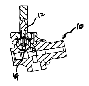
Figure 4 is a sectional side ele~~ation view of the bi-directional tank valve
in Fig_ 1;
Figure 5 is a detailed view of Detail B illustrated in Figure 4;
Figure 6 is a perspective view of the valve piston of of the bi-directional
tank valve in Fig. 1;
Figure 7 is a side elevation view of the valve piston in Fig~.ire 6; and
Figure 8 i,s a bottom plan view of tt~e valve piston in Figure 6.
Description of the Invention
Refexxing to Figures 1 - 5, the present invention provides a bi-directional
tank valve 10,
which is configured to uitigate lateral vibrational movement urged by the flow
of fluid past the
valvel0. In one embodiment, the Fluid is a gaseous fluid.
The tank ~al~e 10 includES a piston 12 disposed within a conduit 14 grad
characterized by a
longitudinal axis 16. The piston 12 includes a sealing surface 18 and a pilot
tip 20, wherein the
sealing surface 18 merges with the pilot tip 20. The sealing surface 18 is
disposed peripheeahy of
the pilot tip 20. 'fhe conduit 14 is characterized by a longitudinal axis 22
parallel to the longitudinal
axis 16 of the piston 12, and includes a valve seat 24 and an orifice 26
disposed within the valve sEat
24. In. this respect, the valve seat 24 is disposed peripherally of the
orifice 26.
The piston 12 is moveable relative to the valve seat 24, and is particularly
moveable along
the longitudinal axis 22 0~ the conduit 14. The piston 12 is characterized by
a first position and a
second position. in the first position, the sealing surface 18 of the piston
12 is sealingly engaged to
the valve seat 24, and the pilot tip 20 extends through the orifice 26. The
sealing surface 18 is
conf gored to close the orifice 26 rwhen sealingly engaged to the valve seat
24. As such, when the
piston 12 is in the first position, the orifice 26 is closed. In the second
position, the sealizxg surface
18 is spaced apart from the valve seat 24, and the orifice 26 is open to
facilitate fluid flow
therethrough. The pilot tip 20 instill disposed within the orifice 2b xz~ the
second position, but does
not cornpletelybloek the flow of gaseous fluid therethroufkx_
The pilot tip 20 extends to, terminates at, azad includes a t~ninal end 28.
The pilot tip 20
further includes an operative surface 30 ox deflector configured tp facilitate
application of a net force
CA 02369640 2002-O1-28
transverse to the longituclinal axis 16 of the piston 12 by fluid flowing
across the operative surface
30, and thereby biassing or urging the piston 12 in a radial or lateral
direction relative to the
longitudinal axis 22 of the condzut 14. In one embodiment, the operative
surface 30 or deflector is
configured in this manner in the case where the fluid is flowing in a
direction remote from the
terminal end ZB of the pilot tip 20 and as indicated by reference character
32. In this respect, the
operafiive surface 30 is configured to change the dir~tional component of the
flow field, such that
the directional component oftbe flow field changes from a directionparallel to
the longitudinal axis
22 ofthe conduit 14 to a direction which is angularly displaced from the
longitudinal axis 22 ofthe
conduit 14.
In one embodiment, the 'operative surface 30 of the pilot tip 20 is tapered or
flared in. a
radially or Laterally outward directiion relative to the longiiudiaal axis 16
of the piston ~2, and
extending in a direction remote ~rom the tenniaal end 28 of the pilot tip 20,
and is asymmetrically
dispQSed about the longitudinal axis 16 of the piston 12.
Referring to Figlzres 6- 8, in one embodiment, three scallops 34 are formed in
the pilot tip
20 of the piston. I2, presenting asy'zumetrically tapered surfaces about the
longitudinal axis 16 of the
piston 12. The asymmetric configuration is important to facilitate application
of a net force
transverse to the longitudinal axis I6 of the piston 12 as gas flows past the
piston 12. In this way,
the piston 12 is biassed in a direction. transverse to the longitudinal axis
22 ofthe conduit 14 and is,
therefore, less prone to vibrations caused by unbalanced fluid forces
generated by fluid flowing past
the piston 12.
In one embodiment, and as more clearly illustrated in Figuze 1, the bi-
directional tank valve
is a two-stage valve which is urged to seal the ori~xce by a resilient member,
such as a
compression spring. The two-stage valve is actuated to become unseated
relative to the valve seat
by a solenoid coil housed in the body of the valve_
