Language selection

Search

Patent 2369693 Summary

Third-party information liability

Some of the information on this Web page has been provided by external sources. The Government of Canada is not responsible for the accuracy, reliability or currency of the information supplied by external sources. Users wishing to rely upon this information should consult directly with the source of the information. Content provided by external sources is not subject to official languages, privacy and accessibility requirements.

Claims and Abstract availability

Any discrepancies in the text and image of the Claims and Abstract are due to differing posting times. Text of the Claims and Abstract are posted:

  • At the time the application is open to public inspection;
  • At the time of issue of the patent (grant).
(12) Patent: (11) CA 2369693
(54) English Title: REUSABLE RIVET
(54) French Title: RIVET REUTILISABLE
Status: Deemed expired
Bibliographic Data
(51) International Patent Classification (IPC):
  • F16B 19/10 (2006.01)
  • F16B 13/06 (2006.01)
  • F16B 13/08 (2006.01)
(72) Inventors :
  • EDLAND, DAVID W. (United States of America)
(73) Owners :
  • ILLINOIS TOOL WORKS INC. (United States of America)
(71) Applicants :
  • ILLINOIS TOOL WORKS INC. (United States of America)
(74) Agent: FINLAYSON & SINGLEHURST
(74) Associate agent:
(45) Issued: 2006-10-10
(22) Filed Date: 2002-01-30
(41) Open to Public Inspection: 2002-08-06
Examination requested: 2002-01-30
Availability of licence: N/A
(25) Language of filing: English

Patent Cooperation Treaty (PCT): No

(30) Application Priority Data:
Application No. Country/Territory Date
09/777,300 United States of America 2001-02-06

Abstracts

English Abstract


The rivet includes a screw element which rotates within a body element.
The body element includes an upper collar, integral with the body head, which
is
longitudinally stabilized with respect to the rotating screw element. The body
element
further includes a lower collar which is internally threaded and engages the
external
threads of the shank of the screw element. The lower collar therefore
traverses a
portion of the shank of the screw element as the screw element rotates.
Folding legs
join the upper collar and the lower collar. In the uninstalled position, the
folding legs are
parallel to and abut the screw shank. However, in the installed position, the
lower collar
approaches the upper collar and the legs fold so as to be substantially
perpendicular to
the screw shank.


Claims

Note: Claims are shown in the official language in which they were submitted.


What is claimed is:

1. A rivet comprising:
a screw element including a screwhead and a shank, said shank including
a threaded portion, said screw element rotating about a longitudinal axis;
a body element, including an aperture through which said screw element
extends, said body element further including a head and a lower collar,
wherein
said head and said lower collar are attached by a plurality of folding legs,
and said
lower collar longitudinally traverses a portion of said screw element during
rotation
of said screw element;
said screw element including a first longitudinally stabilizing element and
said
head including a second longitudinally stabilizing element, wherein said first
longitudinally stabilizing element engages said second longitudinally
stabilizing
element, whereby said screw element is longitudinally stabilized with respect
to
said head during rotation of said screw element;
said first longitudinally stabilizing element being a rotational disk and said
second longitudinally stabilizing element being a circular groove, and wherein
said
rotational disk is engaged within said circular groove.

2. The rivet of claim 1 wherein said body element further includes an upper
collar integral with said head, said screwhead abutting said head.

3. The rivet of claim 2 wherein said screwhead includes grooves for
engagement by an installing tool.

4. The rivet of claim 3 wherein said lower collar includes internal threads
which
threadably engage said threaded portion of said shank.

5. The rivet of claim 4 wherein the rivet has an uninstalled position and an
installed position, wherein said legs extend parallel to and abut said shank
in said
uninstalled position and wherein said legs fold and extend substantially
perpendicular from said shank in said installed position.

-6-


6. The rivet of claim 5 wherein said shank terminates in an enlarged portion
to
limit travel of said lower collar along said shank.

7. The rivet of claim 6 wherein said lower collar abuts said enlarged portion
in
said uninstalled position and wherein said lower collar is proximate to said
upper
collar in said installed position.

8. The rivet of claim 7 wherein said screw element is formed by a first shot
of
a two-shot molding process and said body element is formed by a second shot of
the two-shot molding process.

9. The rivet of claim 8 wherein said screw element is formed of glass filled
nylon 6/6 and said body element is formed of nylon 6/6.

10. A rivet comprising:
a screw element including a screwhead and a shank, said shank including
a threaded portion, said screw element rotating about a longitudinal axis;
a body element, including an aperture through which said screw element
extends, said body element further including a head and a lower collar,
wherein
said head and said lower collar are attached by a plurality of folding legs;
said screwhead abutting a top of said head in both an installed and an
uninstalled position; and
means for longitudinally stabilizing said screw element with respect to said
body element during rotation of said screw;
said lower collar longitudinally traversing a portion of said screw element
during rotation of said screw element; and
said shank terminating in an integral enlarged portion which has a diameter
substantially equal to that of said lower collar and is substantially free of
longitudinal movement during rotation of said screw elements.

-7-


11. The rivet of claim 10, wherein said means for longitudinally stabilizing
comprises a rotational disk on said screw element and a circular groove on
said
body element and, wherein said rotational disk is engaged within said circular
groove.

12. The rivet of claim 11 wherein said body element further includes an upper
collar integral with said head.

13. The rivet of claim 12 wherein said screwhead includes grooves for
engagement by an installing tool.

14. The rivet of claim 13 wherein said lower collar includes internal threads
which threadably engage said threaded portion of said shank.

15. The rivet of claim 14 wherein the rivet has an uninstalled position and an
installed position, wherein said legs extend parallel to and abut said shank
in said
uninstalled position, and wherein said legs fold and extend substantially
perpendicular from said shank in said installed position.

16. The rivet of claim 15 wherein said integral enlarged portion limits travel
of
said lower collar along said shank.

17. The rivet of claim 16 wherein said lower collar abuts said enlarged
portion
in said uninstalled position and wherein said lower collar is proximate to
said upper
collar in said installed position.

18. The rivet of claim 17 wherein said screw element is formed by a first shot
of a two-shot molding process and said body element is formed by a second shot
of the two-shot molding process.

19. The rivet of claim 18 wherein said screw element is formed of glass filled
nylon 6/6 and said body element is formed of nylon 6/6.

-8-


20. A rivet comprising:
a screw element including a screwhead and a shank, said shank including
a threaded portion, said screw element rotating about a longitudinal axis;
a body element further including a head and a lower collar, wherein said
head and said lower collar are attached by a plurality of folding legs;
said screwhead abutting a top of said head in both an installed and an
uninstalled position;
means for longitudinally stabilizing said screw element with respect to said
body element during rotation of said screw;
said lower collar longitudinally traversing a portion of said screw element
during rotation of said screw element; and
said shank terminating in an integral enlarged portion having a diameter
substantially equal to that of said lower collar and including rotationally
tapered
walls, said lower collar abutting said integral enlarged portion prior to a
folding of
the legs; and
said lower collar moving away from said integral enlarged portion during the
folding of said legs in response to rotation of said screw element.

21. The rivet of claim 20, wherein said means for longitudinally stabilizing
comprises a rotational disk on said screw element and a circular groove on
said
body element and, wherein said rotational disk is engaged within said circular
groove.

22. The rivet of claim 21 said body element further includes an upper collar
integral with said head.

23. The rivet of claim 22 wherein said screwhead includes grooves for
engagement by an installing tool.

24. The rivet of claim 23 wherein said lower collar includes internal threads
which threadably engage said threaded portion of said shank.

-9-


25. The rivet of claim 24 wherein the rivet has an uninstalled position and an
installed position, wherein said legs extend parallel to and abut said shank
in said
uninstalled position, and wherein said legs fold and extend substantially
perpendicular from said shank in said installed position.

26. The rivet of claim 25 wherein said screw element is formed by a first shot
of a two-shot molding process and said body element is formed by a second shot
of the two-shot molding process.

27. The rivet of claim 26 wherein said screw element is formed of glass filled
nylon 6/6 and said body element is formed of nylon 6/6.

-10-


Description

Note: Descriptions are shown in the official language in which they were submitted.


CA 02369693 2002-04-26
REUSABLE RIVET
BACKGROUND OF THE INVENTION
Field of the Invention
This invention pertains to a reusable rivet, which is formed by a two- shot
molding process, wherein a central rotatable screw element drives a lower
threaded
collar of a body element so that folding legs extend into an engaged position.
Description of the Prior Art
In the prior art, rivets of various kinds are known. However, the installed
position of many rivets includes the inelastic deformation of metal, so that
removal of
the rivet typically destroys the rivet so that subsequent use is not possible.
Similarly,
some rivets may include locking engagement which is not meant to be reversible
so that
the removal of the rivet requires that the rivet be torn or ripped in a way
such that
subsequent re-use is not possible.
Additionally, many rivets include two pieces which are manufactured and
even shipped separately and assembled immediately prior to installation. Such
a design
increases the manufacturing, shipping and assembly costs.
' Examples of prior art rivets may be found in U.S. Patent No. 5,690,454
entitled "Anchoring Retainer for Threaded Fasteners", issued on November 25,
1997
to Smith; U.S. Patent No. 4,776,737 entitled "Re-Usable Two-Piece Blind
Fastener",
issued on October 11, 1988 to Wollar; U.S. Patent No. 4,659,269 entitled
"Fastening
Dowel of Plastics", issued on April 21, 1987 to Stromiedel and U.S. Patent No.
4,274,324 entitled "Hollow Wall Screw Anchor", issued on June 23, 1981 to
Giannuzzi.
-1-


t CA 02369693 2005-04-22
SUMMARY OF THE INVENTION
Accordingly, the present invention seeks to provide a rivet which is reusable.
Further, the present invention seeks to provide a rivet which minimizes
inelastic deformations during installation.
Further still, the present invention seeks to provide a rivet which can be
removed from the installed position without damaging the rivet and which can
be
re-used.
Still further, the present invention seeks to provide a rivet which can be
manufactured and shipped as a single unit.
Moreover, the present invention seeks to provide a rivet which can be
installed and removed with standard tools, in an ergonomically intuitive
manner.
These and other aspects are attained by providing a rivet with a body
element with a head and a lower internally threaded collar which are joined by
foldable legs. A screw element includes a screwhead and is rotatable but
longitudinally stabilized within the head of the body. The screw element
further
includes a threaded shank with an enlarged lower end. The lower internally
threaded collar is threadably engaged with the threaded shank and moves
longitudinally bounded by the head of the body and the enlarged lower end of
the
threaded shank. When the lower internally threaded collar is against the
enlarged
lower end of the threaded shank, the legs of the body abut and are parallel to
the
threaded shank. This is the uninstalled position. However, as the internally
threaded collar is driven toward the head of the body, the legs fold so as to
be
perpendicular to the threaded shank and thereby form the installed position.
Still further, the present invention seeks to provide a rivet comprising a
screw element including a screwhead and a shank, the shank including a
threaded
portion, the screw element rotating about a longitudinal axis. A body element
further includes a head and a lower collar, the head and the lower collar
being
attached by a plurality of folding legs. The screwhead abuts a top of the head
in
both an installed and an uninstalled position. Means is provided for
longitudinally
stabilizing the screw element with respect to the body element during rotation
of
-2-


CA 02369693 2005-04-22
the screw, the lower collar longitudinally traversing a portion of the screw
element
during rotation of the screw element. The shank terminates in an integral
enlarged
portion and has a diameter substantially equal to that of the lower collar and
includes rotationally tapered walls. The lower collar abuts the integral
enlarged
portion prior to a folding of the legs and the lower collar moves away from
the
integral enlarged portion during the folding of the legs in response to
rotation of the
screw element.
The rivet is formed by a two-shot molding process, wherein the screw
element is first molded from a glass filled nylon 6/6 or similar material and
then the
body element is molded around the screw element from nylon 6/6 or similar
material.
-2a-


CA 02369693 2005-04-22
r .
BRIEF DESCRIPTION OF THE DRAWINGS
Further aspects and advantages will become apparent from the following
description and claims and from the accompanying drawings, wherein:
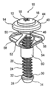
Figure 1 is a perspective view of the reusable rivet of the present invention,
shown in the uninstalled position.
Figure 2 is a cross-sectional view of the reusable rivet of the present
invention, shown in the uninstalled position.
Figure 3 is a perspective view of the reusable rivet of the present invention,
shown with the internally threaded collar moving toward the installed
position.
Figure 4 is a perspective view of the reusable rivet of the present invention
in the installed position with the internally threaded collar in the uppermost
position,
with the legs folded perpendicularly to the shank of the screw element.
Figure 5 is a cross-sectional view of the reusable rivet of the present
invention, shown in the installed position with respect to the primary and
secondary
panels.
DETAILED DESCRIPTION OF THE PREFERRED EMBODIMENT
Referring now to the drawings in detail wherein like numerals indicate like
elements throughout the several views, one sees from Figure 1 that rivet 10 of
the
present invention includes screw element 12 and body element 14.
Screw element 12 rotates about longitudinal axis 100 and includes
screwhead 16 which includes Phillips-head or similar grooves 18. Unthreaded
shank
portion 20 extends from screwhead 16 and includes disk-shaped locking ring 22
which,
as will be explained hereinafter, stabilizes the screw element 12
longitudinally with
respect to the head of the body element 14.
Threaded shank portion 24 extends from unthreaded shank portion 20. As
can be seen in Figures 3 and 4, the threads 26 of threaded shank portion 24
may be
segmented in intermediate longitudinal areas. Lower head 28, in the shape of
an
-3-


CA 02369693 2005-04-22
inverted truncated cone, is formed at the distal end 30 of threaded shank
portion 24.
Base 32 of lower head 28 forms a stop at the distal end 30 of threaded shank
portion
24. Likewise, inclined walls 34 of base 32 form a chamfered toroidal surface
for
guiding rivet 10 into an aperture of a panel or other structure.
Body element 14 includes disk-shaped head 40 with a tower surface 42
which serves as a stop against secondary panel 300 (see Figure 5). Likewise,
body
disk-shaped head 40 has an upper surface 44 against which head 16 of screw
element
12 abuts. Central aperture 43 passes through disk-shaped head 40 with
unthreaded
shank portion 20 of screw element 12 inserted therethrough. Upper square
collar 46
is formed integrally with disk-shaped head 40. As central aperture 43 passes
through
upper square collar 46, internal circular groove 48 is formed to rotationally
engage
disk-shaped locking ring 22 of unthreaded shank portion 20 of screw element
12. This
allows rotation of screw element 12 within body element 14, while
longitudinally
stabilizing screw element 12 with respect to upper square collar 44. The
square shape
of upper square collar 44 (other shapes can be chosen) is to engage the
complementary
square-shaped aperture 302 of primary panel 300 as shown in Figure 5.
Round portion 50 is formed below upper square collar 46 with four folding
legs 52, 54, 56, 58 extending therefrom. Four folding legs 52, 54, 56, 58, in
the initial
as-molded and uninstalled position as shown in Figures 1 and 2, extend
parallel and
outwardly adjacent from threaded shank portion 24 to lower internally threaded
collar
60. Lower internally threaded collar 60 is formed integrally with folding legs
52, 54,
56, 58'and extends circumferentially about threaded shank portion 24. The
revolution
or screwing movement of screw element 12 with respect to body element 14
causes
lower threaded collar 60 to travel longitudinally along threaded shank portion
24. In the
initial as-molded and uninstalled position shown in Figures 1 and 2, lower
internally
threaded collar 60 abuts lower head 28, the travel of lower internally
threaded collar 60
being stopped thereby.
Rivet 10 is typically molded by a two-shot process. The screw element 12
is molded in the first shot using a glass filled nylon 6/6 or similar
material. The mold
Inot shown) opens and the platen rotates 180 degrees. The mold closes on the
screw
-4-


CA 02369693 2005-04-22
element 12 and a second resin, such as nylon 6/6 or similar material, is
injected
into the mold cavity to form the body. The mold opens and a finished unitary
rivet
is ejected. The rivet 10 is then ready to be shipped as a single piece to the
customer.
To install rivet 10, the end customer typically inserts rivet 10 through a
square aperture 302 in the secondary panel 300 and into the aperture 202 in
the
primary panel 200. Upper square collar 46 is engaged by square aperture 302
and
lower surface 42 of head 40 of body element 14 is flush against secondary
panel
300. An air gun or similar tool is used to engage grooves 18 of screw element
12
and rotate screw element 12, typically in a standard clockwise direction. As
screw
element 12 is turned, lower internally threaded collar 60 moves longitudinally
upwardly toward head 40 of body element 14. As shown in Figures 3, 4 and 5,
legs 52, 54, 56, 58 buckle outwardly as collar 60 moves upwardly, until legs
52,
54, 56, 58 are substantially perpendicular to screw element 12. When the fully
installed position of Figures 4 and 5 is reached, the torque will increase
causing the
air gun to stop.
In order to subsequently remove rivet 10, screw element 12 is rotated in the
opposite, typically counterclockwise, direction. Screw element 12 will not
back
out of body element 14 due to locking ring 22 being engaged by circular groove
48. Therefore, lower internally threaded collar 60 will move down threaded
shank
portion 24 from the position shown in Figures 4 and 5 toward the position
shown
in Figures 1 and 2. The torque will increase when lower internally threaded
collar
60 abuts lower head 28, causing the air gun to stop. It is envisioned that
little or
no inelastic deformation will have occurred to rivet 10 during installation
and
subsequent removal, so that rivet 10 can be installed repeatedly.
Thus the several aforementioned objects and advantages are most effectively
attained. Although a single preferred embodiment of the invention has been
disclosed and described in detail herein, it should be understood that this
invention
is in no sense limited thereby and its scope is to be determined by that of
the
appended claims.
_5_

Representative Drawing
A single figure which represents the drawing illustrating the invention.
Administrative Status

For a clearer understanding of the status of the application/patent presented on this page, the site Disclaimer , as well as the definitions for Patent , Administrative Status , Maintenance Fee  and Payment History  should be consulted.

Administrative Status

Title Date
Forecasted Issue Date 2006-10-10
(22) Filed 2002-01-30
Examination Requested 2002-01-30
(41) Open to Public Inspection 2002-08-06
(45) Issued 2006-10-10
Deemed Expired 2010-02-01

Abandonment History

There is no abandonment history.

Payment History

Fee Type Anniversary Year Due Date Amount Paid Paid Date
Request for Examination $400.00 2002-01-30
Registration of a document - section 124 $100.00 2002-01-30
Application Fee $300.00 2002-01-30
Maintenance Fee - Application - New Act 2 2004-01-30 $100.00 2004-01-14
Maintenance Fee - Application - New Act 3 2005-01-31 $100.00 2005-01-07
Maintenance Fee - Application - New Act 4 2006-01-30 $100.00 2006-01-04
Final Fee $300.00 2006-07-28
Maintenance Fee - Patent - New Act 5 2007-01-30 $200.00 2007-01-02
Maintenance Fee - Patent - New Act 6 2008-01-30 $200.00 2008-01-02
Owners on Record

Note: Records showing the ownership history in alphabetical order.

Current Owners on Record
ILLINOIS TOOL WORKS INC.
Past Owners on Record
EDLAND, DAVID W.
Past Owners that do not appear in the "Owners on Record" listing will appear in other documentation within the application.
Documents

To view selected files, please enter reCAPTCHA code :


To view images, click a link in the Document Description column. To download the documents, select one or more checkboxes in the first column and then click the "Download Selected in PDF format (Zip Archive)" or the "Download Selected as Single PDF" button.

List of published and non-published patent-specific documents on the CPD .

If you have any difficulty accessing content, you can call the Client Service Centre at 1-866-997-1936 or send them an e-mail at CIPO Client Service Centre.


Document
Description 
Date
(yyyy-mm-dd) 
Number of pages   Size of Image (KB) 
Claims 2002-01-30 3 92
Abstract 2002-01-30 1 29
Abstract 2002-04-26 1 21
Description 2002-04-26 5 230
Description 2002-01-30 8 320
Drawings 2002-01-30 2 145
Representative Drawing 2002-05-02 1 23
Claims 2002-04-26 2 65
Cover Page 2002-08-02 1 52
Claims 2005-10-14 5 169
Description 2005-04-22 6 252
Claims 2005-04-22 5 169
Drawings 2005-04-22 2 48
Representative Drawing 2006-09-19 1 10
Cover Page 2006-09-19 1 40
Correspondence 2002-03-05 1 17
Assignment 2002-01-30 6 304
Correspondence 2002-04-26 9 342
Prosecution-Amendment 2005-10-14 5 126
Prosecution-Amendment 2004-11-02 2 80
Prosecution-Amendment 2005-04-22 18 586
Prosecution-Amendment 2005-09-12 1 33
Correspondence 2006-07-28 1 31