Note: Descriptions are shown in the official language in which they were submitted.
CA 02370009 2002-02-01
1
1 SURVEYING OF BOREHOLES
2
3 This invention relates to the surveying of
4 borehbles, and relates more particularly but not
exclusively to determining the true azimuth of a
6 borehole.
7
8 When drilling a well for exploration and recovery of
9 oil or gas, it is known to drill a deviated well,
which is a well whose borehole intentionally departs
11 from vertical by a significant extent over at least
12 part of its depth. When a single drilling rig is
13 offshore, a cluster of deviated wells drilled from
14 that rig allows a wider area and,a bigger volume to
be tapped from the single drilling rig at one time
16 and without expensive and time-consuming relocation
17 of the rig than by utilising only undeviated wells.
18 Deviated wells also allow obstructions to be by-
19 passed during drilling, by suitable control of the
deviation of the borehole as it is drilled.
21 However, to obtain the full potential benefits of
22 well deviation requires precise knowledge of the
CA 02370009 2002-02-01
2
1 instantaneous location and heading of the bottom-
2 hole assembly (including the drilling bit and
3 steering mechanisms such as adjustable stabilisers).
4 Depth of the bottom-hole assembly (or axial length
of the borehole) can be determined from the surface,
6 for example by counting the number of standard-
7 length tubulars coupled into the drill string, or by
8 less empirical procedures. However, determination
9 of the location and heading of the bottom-hole
assembly generally requires some form of downhole
11 measurement of heading. Integration of heading
12 with respect to axial length of the borehole will
13 give the borehole location relative to the drilling
14 rig.
16 In this context, the word "heading" is being used to
17 denote the direction in which the bottom-hole
18 assembly is pointing (ie. has its longitudinal axis
19 aligned), both in a horizontal and vertical sense.
Over any length of the borehole which can be
21 considered.as straight for the purposes of
22 directional analysis, the borehole axis in a
23 deviated well will have a certain inclination with
24 respect to true vertical. A vertical plane
including this nominally straight length of borehole
26 will have a certain angle (measured in a horizontal
27 plane) with respect to a vertical plane including a
28 standard direction; this standard direction is
29 hereafter taken to be true magnetic north, and the
said angle is the magnetic azimuth of the length of
31 the borehole under consideration (hereafter simply
32 referred to as "azimuth"). The combination of
a '= CA 02370009 2002-02-01
3
1 inclination and azimuth at any point down the
2 borehole is the heading of the borehole at that
3 point; borehole heading can vary with depth as might
4 be the case, for example, when drilling around an
obstacle.
6
7 Instrumentation packages are known, which can be
8 incorporated into bottom-hole assemblies to measure
9 gravity and magnetism in a number of orthogonal
directions related to the heading of the bottomhole
11 assembly. Mathematical manipulations of
12 undistorted measurements of gravitational and
13 magnetic vectors.can produce results which are
14 representative of the true heading at the point at
which the readings were taken. However, the
16 measurements of magnetic vectors are susceptible to
17 distortion, not least because of the masses of
18 ferrous materials incorporated in the drill string
19 and bottom-hole assembly. Distortion of one or
more magnetic vector measurements can give rise to
21 unacceptable errors in the determination of heading,
22 and undesirable consequences. Distortion of
23 magnetic vectors in the region of the
24 instrumentation arising from inherent magnetism of
conventional drill string and bottom-hole assembly
26 components can be mitigated by locating,the
27 instrumentation in a special section of drill string
28 which is fabricated of non-magnetic alloy.
29 However, such special non-magnetic drill string
sections are relatively expensive. Moreover, the
31 length of non-magnetic section required to bring
32 magnetic distortion down to an acceptable level
CA 02370009 2002-02-01
4
1 increases significantly with increased mass of
2 magnetic bottom-hole assembly and drill string
3 components, with consequent high cost in wells which
4 use such heavier equipment, e.g. wells which are
longer and/or deeper. Hence such forms of passive
6 error correction may be economically unacceptable.
7 Active error correction by the mathematical
8 manipulation of vector readings which are assumed to
9 be error-free or to have errors which are small may
give unreliable results if the assumption is
11 unwarranted.
12
13 Before describing the invention, several definitions
14 will be detailed with reference to Figs: 1 and 2 of
the accompanying drawings, wherein:-
16
17 Fig. 1 is a schematic elevational view of the
18 bottom-hole assembly of a drill string; and
19
Fig. 2 is a schematic perspective view of
21 various axes utilised for denoting directions
22 in three dimensions.
23
24 Referring first to Fig. 1, the bottom-hole assembly
of a drill string comprises a drilling bit 10
26 coupled by a non-magnetic drill collar 12 and a set
27 of drill collars 14 to a drill pipe 16. The drill
28 collars 14 may be fabricated of a magnetic material,
29 but the drill collar 12 is substantially devoid of
any self-magnetism.
31
CA 02370009 2002-02-01
1 During local gravity and magnetic field vector
2 measurements, the non-magnetic drill collar 12
3 houses a downhole instrumentation package
4 schematically depicted at 18. (In reality, the
5 package 18 would not be visible as is apparently the
6 case in Fig. 1 since the package 18 is utilised
7 within the interior of the collar 12). The
8 downhole instrumentation package 18 is capable of
9 measuring gravity vectors and local magnetic
vectors, for example by the use of accelerometers
11 and fluxgates respectively. The instrumentation
12 package 18 may be axially and rotationally fixed
13 with respect to the bottom-hole assembly, including
14 the drilling bit 10, whose heading is to be
determined; the instrumentation package 18 would
16 then be rigidly mounted in the bottom-hole assembly,
17 within the non-magnetic drill collar 12 which is
18 fabricated of non-magnetic alloy. Alternatively,
19 the package 18 could be lowered through the collar
12, either on a wireline or as a free-falling
21 package, with internal recording of the local
22 gravity vectors and the local magnetic vectors.
23 The alternative procedures for measurement
24 processing according to whether the instrumentation
package 18 is axially fixed or mobile will be
26 subsequently described.
27
28 Referring now to Fig. 2 for convenience of
29 conceptual presentation and calculation references,
a hypothetical origin or omni-axial zero point "0"
31 is deemed to exist in the centre of the
32 instrumentation package 18 (not shown in Fig. 2).
CA 02370009 2002-02-01
6
1 Of the three orthogonal axes OX, OY and OZ defining
2 the alignment of the instrumentation relative to the
3 bottom-hole assembly, the OZ axis lies along the
4 axis of the bottom-hole assembly, in a direction
towards the bottom of the assembly and the bottom of
6 a borehole 20 drilled by the drilling bit 10. The
7 OX and OY axes, which are orthogonal to the OZ axis
8 and therefore lie in a plane 0.N2.E1 (now defined as
9 the "Z-plane") at right angles to the bottom-hole
assembly axis OZ, are fixed with respect to the body
11 (including the collar 12) of the bottom-hole
12 assembly. As viewed from above, the OX axis is the
13 first of the fixed axes which lies clockwise of the
14 upper edge of the (inclined) bottom-hole assembly,
this upper edge lying in the true azimuth plane
16 0.N2.Nl.V of the bottom-hole assembly. The angle
17 N2ØX. in the Z-plane 0.N2.E1 (at right angles to
18 OZ axis) between the bottom-hole assembly azimuth
19 plane 0.N2.N1.V and the OX axis is the highside
angle "HS". The OY axis lies in the Z-plane
21 0.N2.E1 at right angles to the OX axis in a
22 clockwise direction as viewed from above. A
23 gravity vector-measuring accelerometer (or other
24 suitable device) is fixedly aligned with each of the
OX, OY and OZ axes. A magnetic vector-measuring
26 fluxgate (or other suitable device) is fixedly
27 aligned in each of the OX, OY and OZ axes. The
28 instrumentation package 18 may be energised by any
29 suitable known arrangement, and the instrumentation
readings may be telemetered directly or in coded
31 form to a surface installation (normally the
32 drilling rig) by any suitable known method, or
CA 02370009 2002-02-01
7
1 alternatively the instrumentation package 18 may
2 incorporate computation means to process
3 instrumentation readings and transmit computational
4 results as distinct from raw data, or the
instrumentation package 18 may incorporate recording
6 means for internal recording of the local axial
7 magnetic vectors for subsequent retrieval of the
8 package 18 and on-surface processing of the recorded
9 measurements.
11 Also notionally vectored from the origin 0 are a
12 true vertical (downwards) axis OV, a horizontal axis
13 ON pointing horizontally to true Magnetic North, and
14 an OE axis orthogonal to the OV and ON axes, the OE
axis being at right angles clockwise in the
16 horizontal plane as viewed from above (ie. the OE
17 axis is a notional East-pointing axis).
18
19 The vertical plane O.N2.Nl.V including the OZ axis
and OV axis is.the azimuth plane of the bottom-hole
21 assembly. The angle V.O.Z. between the OV axis and
22 the OZ axis, ie. the angle in the bottom-hole
23 assembly azimuth plane O.N2.N1.V, is the bottom-hole
24 assembly inclination angle "INC" which is the true
deviation of the longitudinal axis of the bottom-
26 hole assembly from vertical. Since the angles
27 V.O.N1 and Z.O.N2 are both right angles and also lie
28 in a common plane (the azimuth plane O.N2.,Nl.V), it
29 follows that the angle N1.O.N2 equals the angle
.30 V.O.Z, and hence the angle N1:O.N2 also equals the
31 angle "INC".
CA 02370009 2002-02-01
8
1 The vertical plane O.N.V including the OV axis and
2 the ON axis is the reference azimuth plane or true
3 Magnetic North. The angle N.O.N1 measured in a
4 horizontal plane O.N.NI.E.E1 between the reference
azimuth plane O.N.V. (including the OV axis and the
6 ON axis) and the bottom-hole assembly azimuth plane
7 O.N2.Nl.V (including the OV axis and the OZ axis) is
8 the bottom-hole assembly azimuth angle "AZ".
9
The OX axis of the instrumentation package is
11 related to the true Magnetic North axis ON by the
12 vector sum of three angles as follows:-
13
14 (1) horizontally from the ON axis round Eastwards
(clockwise as viewed from above) to a horizontal
16 axis O.N1 in the bottom-hole assembly azimuth plane
17 O.N2.Nl.V by the azimuth angle AZ (measured about
18 the origin 0 in the horizontal plane);
19
(2) vertically upwards from the horizontal axis
21 O.N1 in the azimuth plane O.N2.N1.V to an inclined
22 axis O.N2 in the Z-plane (the inclined plane O.N2.E1
23 including the OX axis and the OY axis) by the
24 inclination angle INC (measured about the origin 0
in a vertical plane including the origin 0); and
26
27 (3) a further angle clockwise/Eastwards (as defined
28 above) in the Z-plane from the azimuth plane to the
29 OX axis by the highside angle HS (measured about the
origin 0 in the inclined Z-plane O.N2.E1 which
31 includes the origin 0).
CA 02370009 2002-02-01
9
1 Borehole surveying instruments measure the two
2 traditional attitude angles, inclination and
3 azimuth, at points along the path of the borehole.
4 The inclination at such a point is the angle between
the instrument longitudinal axis and the Earth's
6 gravity vector direction (vertical) when the
7 instrument longitudinal axis is aligned with the
8 borehole path at that point. Azimuth is the angle
9 between the vertical plane which contains the
instrument longitudinal axis and a vertical
11 reference plane which may be either magnetically or
12 gyroscopically defined; this invention is concerned
13 with the measurement of azimuth defined by a
14 vertical reference plane containing a defined
magnetic field vector.
16
17 Inclination and azimuth (magnetic) are
18 conventionally determined from instruments which
19 measure the local gravity and magnetic field
components along the directions of the orthogonal
21 set of instrument-fixed axes (OX,OY,OZ);
22 traditionally, OZ is the instrument longitudinal
23 axis. Thus, inclination and azimuth are determined
24 as functions of the elements of the measurement set
(GX,GY,GZ,BX,BY,BZ), where GX is the magnitude of
26 the gravity vector component in direction OX,BX is
27 the magnitude of the magnetic vector component in
28 direction OX, etc. The calculations necessary to
29 derive inclination and azimuth as functions of
GX,GY,GZ,BX,BY,BZ are well known.
31
CA 02370009 2002-02-01
1 When the vertical magnetic reference plane is
2 defined as containing the local magnetic field
3 vector at the instrument location, the corresponding
4 azimuth angle is known as the raw azimuth; i.f the
5 vertical magnetic reference plane is defined as
6 containing the Earth's magnetic field vector at the
7 instrument location, the corresponding azimuth angle
8 is known as absolute azimuth.
9
10 In practice, the value of the absolute azimuth is
11 required and two methods to obtain it are presently
12 employed:
13
14 (i) The instrumentation package is contained
within a non-magnetic drill collar (NMDC)
16 which is sufficiently long to isolate the
17 instrument from magnetic effects caused by
18 the proximity of the drill string (DS)
19 above the instrument and the stabilizers,
bit, etc. forming the bottom-hole assembly
21 (BHA) below the instrument. In this case
22 the Earth's magnetic field is uncorrupted
23 by the DS and BHA and the raw azimuth
24 measured is equal to the absolute azimuth.
26 (ii) The corrupting magnetic effect of the DS
27 and BHA is considered as an error vector
28 along direction OZ thereby leaving BX and
29 BY uncorrupted (components only of the
Earth's magnetic field). The calculation
31 of the absolute azimuth can then be
32 performed as a function of
CA 02370009 2002-02-01
11
1 GX,GY,GZ,BX,BY,Be, where Be is some value
2 (or combination of values) associated with
3 the Earth's magnetic field.
4
The error in the measurement of absolute azimuth by
6 method (ii) is dependent on the attitude of the
7 instrument and may greatly exceed the error in the
8 measurement of the raw azimuth; the reasons for this
9 are summarised as follows:
11 (iii) the need to know the values of Earth's
12 magnetic field components in instrument-
13 magnetic-units to a high degree of'
14 accuracy:
(iv) an inherent calculation error due to the
16 availability of only the uncorrupted
17 cross-axis (BOXY) magnetic vector
18 component. [This is analogous to
19 measuring only the gravity component GZ
and then attempting to determine the
21 inclination (INC) from INC = ACOS (GZ),
22 with the magnitude of Earth's gravity = 1
23 instrument gravity-unit].
24
The foregoing text and Figs. 1 and 2 were extracted
26 from the introduction to GB2229273A, which
27 represents the state of the art over which the
28 present invention is an improved method of surveying
29 of boreholes, as will be detailed below.
31 Recent developments of lon.g-reach directional rotary
32 drilling systems make it desirable to be able to
CA 02370009 2002-02-01
12
1 perform accurate near-bit survey measurements.
2 While it is possible to make the relatively short
3 bottom-hole drilling system (comprising the drill
4 bit, downhole drill motor, and possibly also an
adjustable stabiliser) substantially non-magnetic,
6 the corruption of magnetic field measurements in a
7 near-bit survey instrument package can only be
8 eliminated by the use of long non-magnetic drill
9 collars, or through the use of calculation
correction methods which require measurements of
11 absolute magnetic fields (as described in
12 GB2229237A) and are unsatisfactory for some drilling
13 directions at high inclinations.
14
.15 The present invention allows the accurate
16 measurement
17 of azimuth at a near-bit location in a bottom-hole
18 assembly using only a standard-length non-magnetic
19 drill collar (ie. a non-magnetic drill collar with a
standard length of 30 metres).
21
22 According to a first aspect of the present invention
23 there is provided a method of surveying the magnetic
24 azimuth of a borehole penetrated by a bottom-hole
assembly comprising a magnetic drill string attached
26 to one end of a substantially non-magnetic drill
27 collar to the other end of which is attached a
28 substantially non-magnetic drilling bit assembly, by
29 deriving the true magnitude of the terrestrial
magnetic field BZe in the direction of the
31 longitudinal axis OZ of the borehole in the region
32 of the substantially non-magnetic drill collar, said
CA 02370009 2002-02-01
13
1 method comprising the steps of measuring the
2 longitudinal magnetic field BZ(a) (the component of
3 the magnetic field B in the direction OZ) at a
4 single predetermined point along the length of the
substantially non-magnetic drill collar, and
6 measuring the longitudinal magnetic field BZ(b) at a
7 single predetermined point along the length of the
8 substantially non-magnetic drilling bit assembly, to
9 provide a longitudinal-position-dependent pair of
longitudinal magnetic field measurements BZ(z), and
11 calculating BZe on the basis that BZ(z) = BZe +
12 E(z), where E(z) is the longitudinal-position-
13 dependent longitudinal magnetic field error induced
14 by magnetism of the drill string on the assumption
that the longitudinal magnetic field error E(z) is
16 induced by a single notional magnetic pole in the
17 magnetic drill string substantially at the
18 attachment of the magnetic drill string to the
19 substantially non-magnetic drill collar.
21 The foregoing magnetic azimuth surveying method may
22 optionally be extended to include the measurement of
23 gravity vector components Gx, Gy and Gz and solving
24 the function [Gx,Gy,Gz,Bx,By,BZe] to determine the
borehole heading.
26
27 Other aspects of the present invention provide
28 apparatus for use in the foregoing method, and
29 borehole drilling and surveying equipment
incorporating such apparatus.
31
CA 02370009 2002-02-01
14
1 Embodiments of the invention will now be described
2 by way of example, with reference to Fig. 3 of the
3 accompanying drawings, which is a schematic diagram
4 of a bottom-hole assembly to which the invention is
applied.
6
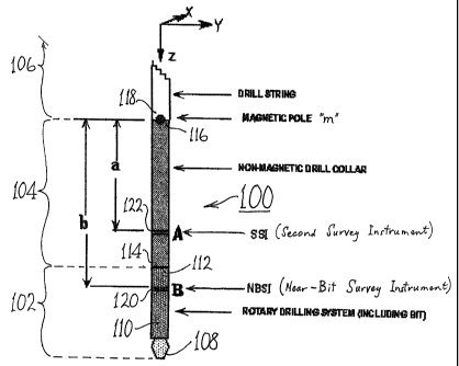
7 Referring to Fig. 3, a bottom-hole assembly 100
8 comprises a drilling bit assembly 102, a non-
9 magnetic drill collar 104, and a drill string 106.
11 The drilling bit assembly 102 comprises a drilling
12 bit 108 and a downhole drilling motor 110. The
13 assembly 102 is fabricated of non-magnetic
14 materials, and is therefore substantially free of
self-magnetism. A direction-controlling stabiliser
16 (not shown) which is also free of self-magnetism may
17 be incorporated in the drilling bit assembly 102 in
18 order to control the directional tendency of further
19 extensions of the borehole (not depicted per se)
drilled by the drilling bit 108, such directional
21 tendency being normally controlled or influenced by
22 the results of borehole surveying in conjunction
23 with intended borehole targets (with possible
24 directional modifications to mitigate unexpected
problems).
26
27 The non-magnetic drill collar 104 is a standard
28 component known per se, being fabricated of non-
29 magnetic materials and having a standard length of
ten metres.
31
CA 02370009 2002-02-01
1 The drill string 106 is a standard assembly of
2 hollow tubular steel pipes interconnected by tapered
3 screw-thread connections to form a mechanical and
4 hydraulic link with a drilling rig (not shown) on
5 the surface of land or sea above the borehole.
6 Since the drill string 106 is fabricated mainly or
7 wholly of ferrous materials, it has self-magnetism
8 which corrupts at least the longitudinal component
9 of magnetic field measurements performed in the
10 bottom-hole assembly 100 near the drilling bit 108.
11
12 The upper end 112 of the drilling bit assembly 102
13 is attached to the lower end 114 of the non-magnetic
14 drill collar 104. The upper end 116 of the non-
15 magnetic drill collar 104 is attached to the lower
16 end 118 of the drill string 106.
17
18 For the purpose of near-bit borehole azimuth
19 surveying in accordance with the invention, the
bottom-hole assembly 100 is fitted at mutually
21 spaced-apart locations with two separate survey
22 instruments, as will now be detailed.
23
24 A near-bit survey instrument ("NBSI") 120 is fitted
within the substantially non-magnetic drilling bit
26 assembly 102 at a location (designated "B") which is
27 at a known fixed distance "b" below the lower end
28 118 of the drill string 106. (The term "below" is
29 used to indicate that the location "B" is closer to
the drilling bit 108 and hence further along the
31 borehole from the surface than the lower end 118 of
32 the drill string 106 notwithstanding that the
CA 02370009 2002-02-01
16
1 borehole may have deviated so far from an initially
2 vertically downwards direction at the surface that
3 the borehole is now horizontal or even headed
4 upwards ) .
6 A second survey instrument ("SSI") 122 is fitted
7 within the non-magnetic drill collar 104 at a
8 location (designated "A") which is at a known fixed
9 distance "a" below the lower end 118 of the drill
string 106. (The term "below" is again used to
11 indicate that the location "A" is closer to the
12 drilling bit 108 and hence further along the
13 borehole from the surface than the lower end 118 of
14 the drill string 106, in the same way that "below"
was used in respect of location "B" as detailed
16 above ) .
17
18 The borehole surveying method in accordance with the
19 invention is based on the assumption that the
magnetic survey-corrupting effects of the drill
21 string 106 can be represented by a single notional
22 magnetic pole of longitudinal magnetic strength "m"
23 and which is located at the lower end 118 of the
24 drill string 106. Details of the method of the
invention, as based on this assumption, willnow be
26 given.
27
28 If the NBSI 120 and the SSI 122 each contain
29 conventional 3-orthogonal-axes gravity (G) and
magnetic (B) transducers then for this
31 configuration, the measured parameters set for the
32 NBSI 120 at position A can be defined by :-
CA 02370009 2002-02-01
17
1
2 {GXa,GYa,GZa,BXa,BYa,BZa} _ {GX,GY,GZ,BX,BY,BZa}
3
4 and that for the SSI 122 at position B by :-
6 {GXb,GYb,GZb,BXb,BYb,BZb} = {GX,GY,GZ,BX,BY,BZb}
7
8 In terms of the conventional Highside, Inclination
9 and Azimuth surveying angles, the corresponding
survey parameter sets are defined by :-
11
12 {HS,INC,AZa} and {HS,INC,AZb}
13
14 Conventional derivations for the Azimuth Angle (AZ)
lead to calculations of AZa and Azb from 16
17 sin(AZa)/cos(AZa) = K1/(K2*BZa + K3)
18
19 and sin (AZb) /cos (AZb) = Kl/ (K2*BZb + K3)
21 where Kl, K2, and K3 are functions of only INC, HS, BX,
22 and BY.
23
24 The corrected azimuth AZc is given by 25
26 sin(AZc)/cos(AZc) = Kl/(K2*BZ + K3)
27
28 where BZ = BZa - Ea = BZb - Eb
29 with Ea = m/a2 = the magnetic error at A due to pole m
and Eb = m/b2 = the magnetic error at B due to pole m
31
32
33 Thus, K2*BZ + K3 = Kl*cot (AZc)
34 K2*BZ + K3 + K2*Ea = K1*cot(AZa)
CA 02370009 2002-02-01
18
] K2*BZ + K3 + K2*Eb = K1*cot(AZb)
2
3 which yield :-
4
Ea = (K1/K2)*[cot(AZa) - cot(AZc)] = m/a2
6
7 and Eb =(K1/K2)*[cot(AZb) - cot(AZc)] = m/b2
8
9 Therefore 10
11 az * [cot (AZa) - cot (AZc) ] = b2 * [cot (AZb) - cot (AZc) ]
12
13 or cot (AZc) * (b2-a2 ) = b2 *cot (AZb) - a2*cot (AZa)
14
Thus it can be shown that the corrected azimuth AZc
16 can be derived from (for example)
17
18 sin(AZc)/cos(AZc) = (b2-a2)*sin(AZa)*sin(AZb)/
19 [b2*sin(AZa)*cos(AZb)-
2 0 aa*sin(AZb)*cos(AZa)]
21
22 or from other equivalent functions of a, b, AZa, and
23 Azb alone.
24
Modifications and variations of the above-described
26 surveying method., and of the instrumentation
27 therefor, can be adopted without departing from the
28 scope of the invention. For example, the survey.
29 instruments 120 and 122 could be simplified to
measure only the longitudinal (Z-axis) magnetic
31 fields at their respective locations "B" and "A",
32 with other instrumentation being utilised to measure
CA 02370009 2002-02-01
19
1 one or more of the omitted parameters if such
2 measurements are deemed necessary or desirable.
3
4 Another possible, although less practicable,
modification is to replace the two magnetic sensors
6 at fixed locations with a single sensor which is
7 transferred or reciprocated between these two
8 locations, with the magnetic field at each being
9 sampled for further processing. This would result
in two non-simultaneous readings, but the time
11 difference would not be significant to the method of
12 the invention provided it is small in relation to
13 movement of the drill string.
14
Other modifications and variations can be adopted
16 without departing from the scope of the invention as
17 defined in the claims.