Note: Descriptions are shown in the official language in which they were submitted.
CA 02370076 2006-07-05
WO 00/62678 PCT/US00/05963
UNITED STATES PATENT APPLICATION FOR:
ULTRASONIC TRANSDUCER WtTH
IMPROVED COMPRESSIVE LOADING
BACKGROUND OF THE INVENTION
The present invention relates generally to ultrasonic transducer
assemblies and, in particular to transducer assemblies of the composite or
sandwich type with a compression assembly for providing a more uniformly
compressive loading to the transducer assembly.
Ultrasonic transmission devices are well known for use in a variety of
applications, such as surgical operations and procedures. The ultrasonic
transmission devices usually include a transducer that converts electrical
energy
into vibrational motion at ultrasonic frequencies. The vibrational motion is
transmitted to vibrate a distal end of a surgical instrument. Such uses are
disclosed in representative U.S. Patent Nos. 3,636,943 and 5,746,756.
High-intensity ultrasonic transducers of the composite or sandwich type
typically include front and rear mass members with alternating annular
piezoelectric transducers and electrodes stacked therebetween. Most such high-
intensity transducers are of the pre-stressed type. They employ a compression
bolt that that extends axially through the stack to place a static bias of
about one-
half of the compressive force that the piezoelectric (PZT) transducers can
tolerate. Sandwich transducers utilizing a bolted stack transducer tuned to a
resonant frequency and designed to a half wavelength of the resonant frequency
are described in United Kingdom Patent No. 868,784. When the transducers
operate they are designed to always remain in compression, swinging from a
minimum compression of nominally zero to a maximum peak of no greater than
the maximum compression strength of the material.
CA 02370076 2001-10-12
WO 00/62678 PCT/US00/05963
-2-
As shown in FIG. 1, an acoustic or transmission assembly 80 of an
ultrasonic device generally includes a transducer stack or assembly 82 and a
transmission component or working member. The transmission component
may include a mounting device 84, a transmission rod or waveguide 86, and an
end effector or applicator 88. The transmission rod 86 and end effector 88 are
preferably part of a surgical instrument.
The transducer assembly 82 of the acoustic assembly 80 converts the
electrical signal from a generator (not shown) into mechanical energy that
results in longitudinal vibratory motion of the end effector 88 at ultrasonic
frequencies. When the acoustic assembly 80 is energized, a vibratory motion
standing wave is generated through the acoustic assembly 80. The amplitude
of the vibratory motion at any point along the acoustic assembly 80 depends on
the location along the acoustic assembly 80 at which the vibratory motion is
measured. The transducer assembly 82, which is known as a "Langevin
stack", generally includes a transduction portion 90, a first resonator or aft
end
bell 92, and a second resonator or fore end bell 94. The transducer assembly
82 is preferably an integral number of one-half system wavelengths (n~,/2) in
length.
The distal end of the first resonator 92 is connected to the proximal end
of transduction section 90, and the proximal end of the second resonator 94 is
connected to the distal end of transduction portion 90. The first and second
resonators 92 and 94 are preferably fabricated from titanium, aluminum, steel,
or any other suitable material. The first and second resonators 92 and 94 have
a length determined by a number of variables, including the thickness of the
transduction section 90, the density and modulus of elasticity of material
used
in the resonators 92 and 94, and the fundamental frequency of the transducer
assembly 82. The second resonator 94 may be tapered inwardly from its
proximal end to its distal end to amplify the ultrasonic vibration amplitude.
CA 02370076 2001-10-12
WO 00/62678 PCT/USOO/05963
-3-
The transduction portion 90 of the transducer assembly 82 preferably
comprises a piezoelectric section ("PZTs") of alternating positive electrodes
96
and negative electrodes 98, with piezoelectric elements 100 alternating
between the electrodes 96 and 98. The piezoelectric elements 100 may be
fabricated from any suitable material, such as, for example, lead zirconate-
titanate, lead meta-niobate, lead titanate, or ceramic piezoelectric crystal
material. Each of the positive electrodes 96, negative electrodes 98, and
piezoelectric elements 100 have a bore extending through the center. The
positive and negative electrodes 96 and 98 are electrically coupled to wires
102
and 104, respectfully. The wires 102 and 104 transmit the electrical signal
from
the generator to electrodes 96 and 98.
The piezoelectric elements 100 are energized in response to the
electrical signal supplied from the generator to produce an acoustic standing
wave in the acoustic assembly 80. The electrical signal causes disturbances in
the piezoelectric elements 100 in the form of repeated small displacements
resulting in large compression forces within the material. The repeated small
displacements cause the piezoelectric elements 100 to expand and contract in
a continuous manner along the axis of the voltage gradient, producing high
frequency longitudinal waves of ultrasonic energy. The ultrasonic energy is
transmitted through the acoustic assembly 80 to the end effector 88.
The piezoelectric elements 100 are conventionally held in compression
between the first and second resonators 92 and 94 by a bolt and washer
combination 106. The bolt 106 preferably has a head, a shank, and a threaded
distal end. The bolt 106 is inserted from the proximal end of the first
resonator
~ 92 through the bores of the first resonator 92, the electrodes 96 and 98,
and
piezoelectric elements 100. The threaded distal end of the bolt 106 is screwed
into a threaded bore in the proximal end of second resonator 94.
Other embodiments of the prior art utilize a stud that is threadedly
engaged with both the first and second resonators 92 and 94 to provide
CA 02370076 2001-10-12
WO 00/62678 PCTIUSOO/05963
-4-
compressive forces to the PZT stack. Threaded studs are also known in the
prior art for attaching and detaching transmission components to the
transducer
assembly. See, for example, U.S. Patent Nos. 5,324,299 and 5,746,756. Such
bolts and studs are utilized to maintain acoustic coupling between elements of
the sandwich type transducer or any attached acoustic assembly. Coupling is
important to maintain tuning of the assembly, allowing the assembly to be
driven in resonance.
The problem with the prior art is that the compression means is inadequate
and is unable to provide a uniform pressure across the inside diameter to the
outside diameter of each PZT and through the entire PZT stack, the "r" and "z"
axes as shown in Fig. 1 and graphically illustrated in Fig. 2. A Finite
Element
analysis shows that the ratio of the pressure in the r axis is of the order of
4:1.
Non-uniform pressure across the r and z axes reduces transducer
efficiency and leads to high heat generation. This limitation becomes acutely
is critical in temperature-limited applications. In temperature-limited
applications,
the reduced efficiency translates into higher heat generation in the
transducer and
reduced maximum output. Further, non-uniform pressure limits the magnitude of
compression and therefore limits the power capability of the transducer.
U.S. Patent 5,798,599 discloses an ultrasonic transducer assembly which
includes soft, aluminum foil washers disposed between facing surfaces of
adjacent members of the PZT stack. The washers deform under compressive
loading to follow the surface irregularities of the adjacent member surfaces.
There is a need therefore, for an ultrasonic transducer that exhibits
substantially uniform compressive stresses across each PZT and throughout the
PZT stack to reduce heat generation and increase power output efficiency. This
invention meets this need.
CA 02370076 2001-10-12
WO 00/62678 PCT/US00/05963
-5-
SUMMARY OF THE INVENTION
The invention is an ultrasonic device with increased efficiency as a result
of substantially increased pressure uniformity across individual PZTs and
through
the PZT stack. The invention comprises a transducer assembly adapted to
vibrate at an ultrasonic frequency in response to electrical energy, the
transducer assembly comprising; a stack of alternating positive and negative
electrodes and piezoelectric elements in an alternating relationship with the
electrodes; a mounting device having a first end and a second end, the
mounting device adapted to receive ultrasonic vibration from the stack and to
transmit the ultrasonic vibration from the first end to the second end of the
mounting device; and structural means for applying compression forces to the
stack, the stack being held together solely by said compression means, and the
compression means comprises a surface for applying compression forces, the
surface having a surface area substantially equivalent to the surface area of
an
individual piezoelectric element.
In a further embodiment the compression means comprises a spacer
element disposed between the surface area and the piezoelectric elements.
The spacer element is configured to comprise a first and second contact area
wherein the first contact area is in contact with the surface area and has a
smaller area than the second contact area, which is in contact with the
proximal
end of the piezoelectric stack.
In one embodiment, the PZT stack is uniformly compressed by way of a
threaded bolt that has a bolt head surface area roughly equal to the surface
area
of the individual piezoelectric elements. The bolt can be further combined
with a
selectively configured end bell that has a first contact surface in contact
with the
bolt head and a second contact surface in contact with the adjacent
piezoelectric
stack. The second contact surface has a greater surface area than the first
contact surface.
CA 02370076 2001-10-12
WO 00/62678 PCT/US00/05963
-6-
An advantage of the current invention is that the transducer thermal and
power efficiencies increase.
A further advantage of the current invention is that heat generation
decreases to a degree that active cooling systems are not necessary.
A still further advantage is that uniform pressure allows larger compression
magnitudes which in turn leads to larger actuation magnitude. A larger
actuation
magnitude results in an increase of the useable range of the PZT.
These and other features and advantages of the present invention will
become apparent from the following more detailed description, when taken in
conjunction with the accompanying drawings which illustrate, by way of
example,
the principles of the invention.
It is to be understood that both the foregoing general description and the
following detailed description are exemplary and explanatory and are intended
to provide further explanation of the invention as claimed.
BRIEF DESCRIPTION OF THE DRAWINGS
FIG. 1 is a cutaway view and in partial cross-section of an embodiment
of a prior art transducer for use in a surgical system;
FIG. 2 is an exemplary contour plot of the pressure loading across each
PZT and through the PZT stack of FIG 1 a;
FIG. 3 is a perspective view of a transducer in accordance with the
invention;
FIG. 4 is a perspective view of the bolt in accordance with the invention;
FIG. 5a is a perspective view of the aft end bell in accordance with the
invention;
FIGS. 5b-g are cross-sectional perspective views of alternate
embodiments of the aft end bell in accordance with the invention;
FIG. 6 is an exemplary contour plot of the pressure loading of each PZT
and through the PZT stack of a transducer in accordance with the invention;
CA 02370076 2001-10-12
WO 00/62678 PCT/USOO/05963
-7-
FIG. 7 is a perspective view of an alternate embodiment of the bolt in
accordance with the invention;
FIG. 8 is a cross-section of the bolt in Fig. 7;
FIG. 9 is a perspective view alternate embodiment of the aft end bell in
accordance with the invention;
FIG. 10 is an elevation view of the embodiment of FIG. 9;
FIG 11 is a perspective view of another alternate embodiment of the aft
end bell in accordance with the invention;
FIG. 12 is an elevation view of the embodiment of FIG. 12;
FIG. 13 is a perspective view of an alternate embodiment of the
invention with two aft end bells disposed on either end of the PZT stack; and
FIG. 14 is a cross-sectional elevation of an alternate means of
compressing the PZT stack in accordance with the invention.
DESCRIPTION OF THE PREFERRED EMBODIMENTS
Before explaining the present invention in detail, it should be noted that
the invention is not limited in its application or use to the details of
construction
and arrangement of parts illustrated in the accompanying drawings and
description. Rather, the illustrative embodiments of the invention may be
implemented or incorporated in other embodiments, variations and
modifications, and may be practiced or carried out in various ways.
Furthermore, unless otherwise indicated, the terms and expressions employed
herein have been chosen for the purpose of describing the illustrative
embodiments of the present invention for the convenience of the reader and
are not for the purpose of limiting the invention.
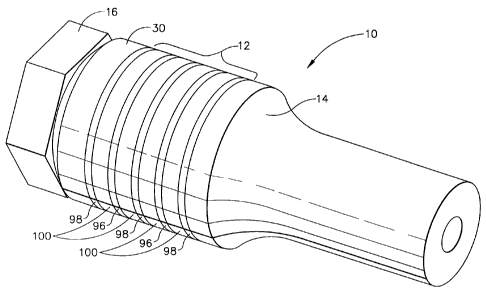
Referring now to Fig. 3, a transducer assembly 10 of the present
invention comprises a PZT stack assembly 12 in combination with a fore end
bell 14. The PZT stack is held in compression by a bolt 16 preferably in
CA 02370076 2006-07-05
WO 00/62678 PCT/US00/05963
-8-
combination with a specially configured aft end bell 30. Preferably, bolt 16
threadedly engages the fore end bell 14 as discussed above.
Figure 4 illustrates bo1t16, which consists of a shank 20 and head 22.
Shank 20 is threaded at its distal end 24 to engage a threaded portion (not
s shown) within the fore end bell 14, Shank 20 flares out at its proximal end
26
where shank 20 meets head 22 to reduce stress concentrations, increase
fatigue life and reduce viscoelastic damping. The geometry of the proximal end
26 is only limited by the design constraints of the associated PZT stack and
the
overall transducer assembly 10. The diameter of bolt head 22 is substantially
equal to the diameters of the individual PZTs. Preferably, bolt 16 is made
from
titanium. Utilizing boltl6"'alone to compressively load PZT stack 12, it was
observed that the pressure distribution across each PZT and through the PZT
stack substantially improved over the prior art compression means.
Specifically, for an equivalent torque applied to the compression means of the
invention and the prior art bolt compression means, an increased output
voltage is observed with the invention.
In an alternate embodiment, bolt 16 is combined with aft end bell 30,
shown in Fig. 5a. Aft end bell 30 has a first contact surface 32 and a second
contact surface 34. The surface area of contact surface 34 is less than the
surface area of contact surface 32. Contact surface 34 contacts with surface
18 of bolt 16, and contact surface 32 contacts the first element of PZT stack
12.
An inner chamfer or offset 36 and an outer chamfer or offset 38 define
contact surface 34. The specific dimension of contact surface 34 may be
optimized through a Finite Element analysis that provides for the greatest
uniform pressure across each PZT and through the PZT stack within the given
space limitations of the transducer assembly. Optimized or not, so long as the
area of contact surface 34 is less than the area of contact surface 32, the
pressure loading of the PZT stack will improve over that of the prior art. By
compressively loading the contact surface 34, stress concentrations uniformly
CA 02370076 2001-10-12
WO 00/62678 PCT/US00/05963
-9-
disperse in the r and z axes and within a short distance of the aft end bell
thickness, thereby reducing the necessary aft end bell thickness required to
evenly distribute the stress. The inner chamfer 36 also advantageously
accommodates the proximal end 26 of shank 20. Preferably, the bevel angle of
the inner and outer chamfer 36 and 38 are equal, but it is not required. An
exemplary bevel angle is 45 .
Utilizing the embodiment of Fig. 3, Fig. 6 illustrates that the ratio of the
pressure along the r axis is of the order of 1.3:1. It is also apparent that
the
compressive forces are more uniform in the z direction at the proximal end of
the PZT stack. Further, the invention also reduces the pressure variation in
the
z direction at the distal end of the PZT stack or at fore end bell surface of
the
stack as compared with the prior art.
Figs. 5b-g illustrate alternate embodiments of aft end bell 30. Each
embodiment defines a respective contact surface 34b-g smaller in surface area
than a respective contact surface 32b-g. A first and second offset 36b-g and
38b-g define each contact surface 34b-g respectively. As is readily apparent,
offsets 36b-g and 38b-g can take on any number of varying geometries to
define contact surface 34b-g.
Table 1, below, compares the measured transducer efficiency of the
present invention with the efficiencies of the prior art.
TABLE 1
PZT Compression Power (W) required for Efficiency Normalized to
Method 1 100 micron the Present Invention
Displacement
Bolt with Head 17.9 74
Stud 16.2 81
1 Present Invention 13.2 100
CA 02370076 2006-07-05 .
WO 00/62678 PCT/US00/05963
-10-
Although the present invention has been described in detail by way of
illustration and example, it should be understood that a wide range of changes
and modifications could be made to the preferred embodiments described
above without departing in any way from the scope and spirit of the invention.
For example, Figs. 7 and 8 illustrate an alternate embodiment of the invention
wherein the aft end bell configuration is an integral element of the bolt head
22.
Multiple aft end bells may be implemented in conjunction with bolt 16. In
this embodiment, a first aft end bell 30 is as shown in Fig. 5. A second aft
end
bell 30a, as shown in Figs. 9 and 10, may be inserted between end bell 30 and
the PZT stack 12. The addition of end beli 30a effectively smoothes out the
pressure variations along the r and z axes more so than with the use of end
bell
30 alone. End bell 30a comprises two contact surfaces 134 and 134a adjacent
to contact surface 32. Contact surface 132 in turn contacts the first
piezoelectric element of PZT stack 12. The specific dimensions of contact
surfaces 134 and 134a are determined by a Finite Element analysis that
provides for the greatest uniform pressure across each PZT and through the
PZT stack within the given space limitations of the transducer assembly.
A third end bell 30b may also be included. The addition of end bell 30b,
as shown in Figs. 11 and 12, between end bell 30a and PZT stack 12
effectively smoothes out the pressure variations along the r and z axes more
so
than with the use of just end bells 30 and 30a. End bell 30b comprises three
contact surfaces 234, 234a and 234b and are adjacent to contact surface 132.
Contact surface 232 in turn contacts the first piezoelectric element of PZT
stack
12. The specific dimensions of contact surfaces 234, 234a and 234b are
determined by a Finite Element analysis that provides for the greatest uniform
pressure across each PZT and through the PZT stack within the given space
limitations of the transducer assembly. As would be readily apparent to those
skilled in the art, additional aft end bells, with a corresponding number of
CA 02370076 2001-10-12
WO 00/62678 PCT/US00/05963
-11-
contact surfaces, may be added to further reduce pressure variations within
the
PZT stack 12.
Further, as would be appreciated by one skilled in the art, one or more
aft end bells may be incorporated between the PZT stack and fore end bell as
shown in Fig. 13. A transducer assembly 110 of the present invention
comprises a PZT stack assembly 112 in combination with a fore end bell 114.
The PZT stack is held in compression by a bolt 116 in combination with a
specially configured aft end bell 130 in accordance with the invention. Bolt
116
threadedly engages the fore end bell 114 as discussed above. Disposed
between fore end bell 114 and PZT stack 112 is a second aft end bell 130a in
accordance with the invention.
Means to hold the PZT stack in compression may include various other
embodiments other than a bolt or stud centrally located along the longitudinal
axis of the PZT stack. Fig. 14 illustrates an alternate embodiment where the
PZT stack 212 is held in compression by way of two end plates 200 and 202
held in place by threaded bolts. In this embodiment, aft end bells 204 and
206,
constructed in accordance with the invention, do not have an annular bore
since the bore is not required to accept a centrally positioned bolt or stud.
Thus, the described embodiments are to be considered in all aspects
only as illustrative and not restrictive, and the scope of the invention is,
therefore, indicated by the appended claims rather than the foregoing
description. All changes that come within the meaning and range of
equivalency of the claims are to be embraced within their scope.