Note: Descriptions are shown in the official language in which they were submitted.
CA 02370154 2001-10-30
Method of Determining the Salt Content of Liquids and
Device for Practicing the Method
Description
The invention relates to a method of determining the salinity of liquids by
standard
calibrated measurements of the electrical conductivity of a liquid sample of
predetermined
temperature in a measuring cell arranged within a cooled and mechanically
stirred as well as
heatable water bath which is insulated to the outside, under controlled
parametric
consideration of the thermal conditions in the water bath, and to a device for
practicing the
method.
State parameters in the thermodynamic sense unequivocally define the state of
a
liquid. Taking sea water in particular as a well-defined liquid, three state
parameters are
sufficient for the definition; all other parameters may be derived therefrom.
The set of
parameters of temperature, salinity and pressure are considered by classical
oceanography as
the simplest and most precisely measurable state parameters. Since about 1960
it has been
possible by using electrical sensors continuously to measure in situ
electrical conductivity,
temperature and pressure of the sea. Instead of the classical parameter
"salinity", "electrical
conductivity" is included in the set of the three measured characteristic
values defining the
state of sea water, because it can be measured more easily in situ and may be
converted into
salinity by means of an empirical normalized formula. Therefore, even though
nowadays the
salinity would no longer be required to define the fluid density, one would
have to have
recourse to it to understand oceanic processes. As a conservative value, the
salinity remains
constant at changes in temperature and pressure, and it is also not affected
by the metabolism
of plants and animals living in the sea. It is subject to simple rules
resulting from the
preservation of the water and salt masses, when sea water of different
salinities is mixed. For
that reason, the salinity is ideally suited for characterizing bodies of water
and as a tracer for
examining large volume currents. But the knowledge of given salinity may also
be important in
other fluids, such as, for instance, pharmaceutical chemistry or food
analyses.
Attomey Docket 010482-US _ 1 _
CA 02370154 2001-10-30
Various methods and apparatus for defining the salinity of fluids are known in
the prior art.
Japanese patent JP 63111457 (1988) discloses a method by which the salinity is
determined
on the basis of the parameters of temperature, pressure and speed of sound. To
this end,
ultra-sonic measuring paths are positioned in a submarine area and the time
lag between
transmitter and receiver of oscillator-generated sinusoidal ultrasound signals
is registered.
Japanese Patent JP 60161554 (1985) discloses another method of carrying out in
situ
measurements of salinity in sea water, in which a coil of appropriate winding
diameter and
length is lowered into the sea in a non-magnetic, non-metallic and waterproof
container and is
charged with an alternate voltage. The magnetic flux then permeates the
surrounding sea
water. The conductivity and, hence, the level of the induction current through
the water is
defined by the salinity. The induction current in the water generates a
counter induction in the
coil which weakens the current in the coil. The measured coil current is then
a direct value of
the salinity of the sea water. The indicated method was introduced as early as
1957 in the
paper "Gerat zur Schnellregistrierung in der Ozeanographie" (Apparatus for
Rapid Registration
in Oceanography) by H. Hinkelmann (Z. f. angewandte Physik einschl. Nukleonik,
Volume IX,
H10, pp. 505-513). The sea water resistance is used as an arm of an almost
balanced
alternate current bridge. By a complex bridge resistance, a phase angle which
depends upon
the sea water resistance is generated between the input and output voltages.
This phase
angle defines the frequency of an oscillator containing the alternate current
bridge. The
corresponding apparatus to carry out the two methods are laboratory devices
for the
calibration of in situ
devices. More detailed descriptions relating to these apparatus may be found
in the papers "A
conductivity bridge for measurement of the salinity of sea-water' (1956,
Schleicher, Bradshaw,
Journal Conseil Permanent International pour I'Exploration de la Mer, Volume
22, pp. 9-20); "A
modification of the Werner-Smith-Soule salinity bridge for the determination
of salinity in sea
water with details of construction, operation and maintenance (Paquette, 1958,
Univ. Of
Washington, Department of Oceanography, Technical Report No. 54-14, pp. 1-57);
"A new
automated laboratory salinometer" (1975, Dauphinee, Klein, Sea Technology,
Volume 16, pp.
23-25) or "Progress in the measurement of salinity and oxygen at the Woods
hole
Oceanographic Institution" (1987, Knapp, Stalcup, Technical Report, WHOI-87-4,
Woods Hole
Oceanographic Institution, pp. 27 seq.).
Attomey Docket 010482-US -2-
CA 02370154 2001-10-30
Japanese Patent JP 62085852 (1987) describes a method of measuring the
salinity in
liquids the temperature of which differs from a reference temperature. To this
end, the
measured conductivity voltage is divided by a temperature-dependent
compensation voltage.
In the apparatus known from the paper "An inductive salinometer" by Brown and
Hamon
(1961, Deep-Sea-Research, Volume 8, pp. 65-71) the temperature dependence is
balanced by
NTC (negative temperature coefficient) -thermistors.
A method of determining salinity is known from Canadian Patent CA 1,199,367 or
its
corresponding American patent US 4,511,845, which is based upon defining a
rate of
conductivity of sample water relative to standard sea water. The essential
contents of these
patents has also been published in the prospectus "Laboratory Salinometer -
Autosal - Model
8400 A" of Guildline Instruments, Ltd., P.O.Box 99, Smith Falls, Ontario, K7A
4S9, Canada.
The invention proceeds from this prospectus as the closest state of the art.
Since this is,
however, merely an apparatus pamphlet, the basic measurement method which has
also been
described in the patents will first be described.
The principle of the method of the Autosal (AS) 8400 is that the electrical
conductivity
of a sea water sample is measured after the form factor of the measuring cell
and the sample
temperature of sea water has been implicitly defined as normal. This assumes
that the form
factor and the temperature will remain constant until a following
standardization. The ratio of
the conductivity of a sample of sea water is defined at a predetermined
temperature relative to
a sample of standard sea water. The salinity is calculated in accordance with
the "Praktische
Salzgehaltsskala of 1978" (Practical Salinity Scale of 1978). The temperature
term of this
formula affects the result of the salinity calculation insignificantly, so
that the actual
temperature during the measurement need not be known precisely. It is,
however, important
that the temperature present at standardization remain stable. As the
conductivity of sea
water is strongly dependent upon temperature every temperature drift fully
affects the result.
For the intended accuracy of the salinity measurement the temperature between
two
standardizations must for this reason be kept constant with great accuracy. In
order to attain
this constancy, which puts great demands on the temperature control and upon
the
maintenance of ambient conditions, the method of operation for attaining the
best possible
accuracy should settle over the course of four days at least. The same applies
following every
Attomey Docket 010482-US -3-
CA 02370154 2001-10-30
disturbance in the operating sequence, for instance, by mistakes in the manual
operation. In
order for the water of the sample attaining the same temperature as the water
bath, the
sample is conducted through a metal capillary positioned in the water bath,
the capillary
functioning as a heat exchanger. Where as a result of too great a difference
in temperatures,
the heat exchanger is incapable of bringing about full temperature
equalization, the second
condition is not met. In case of a deviating sample temperature the heat
exchanger transmits
heats to the bath which may lead to a change in temperature which may exceed
permissible
tolerances.
Operational experience with the measuring method realized with the AS 8400 has
shown that even sample temperature differences permitted by the manufacturer
may lead to
impermissible temperature changes of the water bath. Any occurring
malfunctions cannot be
satisfactorily counteracted. In order to take accurate measurements, it is
thus necessary to
practice the known measuring method in a highly constant climatized room of
the kind for
purposes of field tests are available only on few research ships. In the case
of ships which
have no such complex laboratory equipment the samples must, therefore, be
examined in
institute (home-based) laboratories. However, the usual storage times of at
least four weeks
until the ship returns to its home base, the sample may suffer from
significant changes. In
summary, the known method and the apparatus for practicing it are subject to
too great a
dependence upon the ambient and operating conditions and upon the operating
person.
The problem upon which the present invention is based is thus to be seen in
avoiding
the difficulties arising in connection with the known method and additionally
markedly to
improve a corresponding apparatus for practicing the method by a number of
suitable technical
measures. The aim of the invention is to provide improved measuring precision
by a simple
and safe operation. Furthermore, consideration is also to be given to
automation and
economy.
In the method in accordance with the invention, the problem is solved by the
actual
temperature of the water bath being measured with high repetitive precision as
an equivalent
for the sample temperature, taking into consideration a maximum permissible
lag error
between the temperature of the water bath and the sample as demanded by the
accuracy of
Attomey Docket 010482-US -4-
CA 02370154 2008-03-10
52823-1
the salinity measurement and the control parameters for
considering the thermal conditions derivable from the drift
in time of the temperature of the water bath, the maximum
value of which is defined as the quotient of the maximum
permissible lag error and a time constant of the measuring
cell for balancing the temperature between the interior of
the cell and the water bath.
According to one aspect of the present invention,
there is provided method of determining the salinity of
liquids by standard calibrated measurements of the
electrical conductivity of a heated liquid sample in a
measuring cell arranged in a constantly cooled and
mechanically stirred as well as heatable water bath which is
insulated to the exterior under control parametric
consideration of thermal conditions in the water bath,
wherein an actual temperature ('B) is measured as an
equivalent of a temperature ('P) of the sample with a high
repetitive accuracy and inclusion of a maximum permissible
lag error (A'max) between the water bath and sample
temperature ('B,'P) set by the required accuracy of
determining the salinity (S), and that the control parameter
for taking into account the thermal conditions is a
time-wise drift (a = A 'B/t) of the temperature ('B)
derivable from the temperature measurements, a permissible
maximum value (amax) of which is defined as quotient
(amax - A'max/ T) of the maximum permissible lag error Wmax)
and a time constant (T) of the measuring cell (MC) for a
temperature equalization between the interior of the
measuring cell and the water bath (WB), whereby the
permissible maximum value of the time-wise drift (amax) of
the temperature ('B) of the water bath is maintained by a
low-lag and quickly controllable compensation of heat
-5-
CA 02370154 2008-03-10
52823-1
currents (P ) flowing into and out of the water bath (WB)
to such a degree that the resulting quantity of a residual
heat current (Prest) does not exceed a predetermined maximum
value (Prestmax)
-5a-
CA 02370154 2008-03-10
52823-1
The method in accordance with the invention dispenses with keeping constant
the
temperature of the water bath to accommodate the thermal conditions in the
water bath, the
control of which is extremely difficult primarily because of time lags
occurring in the control
loop. The temperature of the water bath may now adjust itself in accordance
with untouched
ambient conditions. In case of changes, the rate of change only has to stay
within
predetermined limits, otherwise a balance control will intervene. For this
reason, the method
may be practiced in a normal laboratory. The actual water bath temperatures
are measured at
a high repetitive accuracy, i.e. at a high resolution, and are put in
relation, as control
parameters, with the registered interval between individual measurements or
for purposes of a
standard calibration to determine the drift in temperature over time. The
standard calibration is
based upon the actual values of the actually used standard sea water sample,
and allowances
are made for possible calibration errors of the temperature sensor.
Accordingly, to define the
salinity of the liquid sample the indicated temperature of the water bath may
be used without
further consideration of any measuring error of the temperature sensor.
The basic condition for this approach is the assumption of equivalence between
the
sample temperature 'pi relevant to the salinity of the liquid sample liquid
and the water bath
temperature'a which can be measured without substantial influence. The sample
temperature
'P, cannot, however, be sufficiently accurately measured in the measuring cell
without
impermissibly impeding the measurement of the conductivity. In this
connection, the term
"equivalency" is to connote that the equality between the sample temperature
'p and the water
bath temperature 'B is postulated only up to a permissible difference. This
permissible
difference is, in fact, a "lag error" 0' ='e -'p which is caused by the fact
that bath and sample
have not at once the same temperature when the bath temperature 'e changes.
Its maximum
permissible value is determined as "maximum permissible lag error" 0'max:as a
function of the
desired accuracy of the result of the salinity.
-5b-
CA 02370154 2001-10-30
In the first CTD measurements the accuracy of the temperature measurement was
in
the range of 10 mK. However, more precise measurements were made possible as a
result of
progress in the measuring technique. These became mandatory as oceanographers
focussed
on polar regions. There, the present range of values is strongly reduced
relative to the main
ocean, and the range in the vicinity of the freezing point of water in
particular is relevant so that
a correspondingly higher measurement accuracy in the range of 1 mK should be
aimed at. In
order to achieve it, improved measurement processes and components immune from
cross
currents (transverse influences) are required as are reproducible calibration
processes and
more stable standards. The largest permissible error aimed at nowadays, should
be below 10-
3 in the salinity the measurement of which has no unit. This corresponds to a
maximum
relative error of 3=10-5. To this end the temperature or lag error must be
less than 1 mK.
In the method in accordance with the invention the regulation aims at
balancing the
positive and negative heat currents into the water bath so that its
temperature change in time
remains less than a predetermined limit value "maximum permissible drift"
O~õaX. If it is attained
or exceeded the measurements will stop. The control of a resulting heat
current is simpler
than the control of a rigidly determined temperature maintained within narrow
limits, and it
achieves its goal substantially faster than the latter. The control unit us
need now only
recognize a temperature drift and, except for a permissible residual error,
reduce the sum of
the heat currents to zero. A change in ambient conditions now no longer
necessitates
immediate action by the control which is also important as to the measuring
frequency and
evaluation.
To prove the accuracy of the assumption of equivalence of water bath and
sample
temperature and for defining limit values and numeric examples for the values
set forth supra
reference is made to the end of the general description.
An apparatus for practicing the invention is closely connected to the method
in
accordance with the invention and the principles practiced. In order clearly
to set forth these
connections, including different embodiments, and the differences relative to
the prior art, and
in order to prevent repetitions, a preferred apparatus in accordance with the
invention for
practicing the method in accordance with the invention will initially be
explained in greater
Attomey Docket 010482-US _(_
CA 02370154 2001-10-30
detail.
The prior art upon which the invention is based for realizing a corresponding
measuring apparatus is constituted by the generally acknowledged standard
apparatus
"Autosal (AS) 8400" referred to supra, of the Guideline company. This is an
apparatus in
which a liquid of predetermined temperature can be transferred from a sample
bottle to a
measuring cell arranged in a water bath equipped with a means for cooling,
stirring and
heating as well as with a heat exchanger, and which at its wall is provided
with an exterior
insulation, and which is provided with a control unit for adjusting the
thermal conditions in the
water bath. Further explanations of details of the known apparatus will be
given in connection
with corresponding embodiments of the invention.
With a view to distinguishing the apparatus in accordance with the invention
from the
known apparatus, the name "conductivity- reference-measuring-place" (LRM) has
been chosen
for the former. At the time the AS 8400 was conceived, thermometers with long-
time
measuring errors smaller than .3 mK were exceedingly expensive. For that
reason, the known
measuring method aimed to maintain a temperature constant rather than to
measure it.
Modern requirements, however, are no longer satisfied by a constant
temperature of the bath;
this technology is substantially exhausted whereas the present invention is
capable of meeting
substantially higher specifications.
The decisive improvement of the method in accordance with the invention is the
fact
that the temperature is no longer maintained constant; rather, its permissible
change is
measured taking into account the maximum permissible lag error. Errors of the
thermometer
used resulting from insufficient calibration or long-term drift are arrested
by the standardization,
so that the temperature of the water bath is measured directly. In terms of a
device for
practicing the inventive method, the solution to the problem referred to supra
may be seen in a
precision thermometer having a long-time drift of less than 1 mK per year and
a time constant
below .5 s. The precision thermometer may be provided with platinum resistors,
for instance,
and preferably, in a further embodiment of the invention, is provided with
temperature immune
semiconductor resistors. Such thermometers are extremely robust and
insensitive to shock
yet highly accurate. The semiconductor resistors are so-called "hot
conductors" (NTC
Attomey Docket 010482-US -7-
CA 02370154 2001-10-30
thermistors) the resistance values of which decrease with increasing
temperatures. A
temperature selection dial of the kind provided, for instance, in the known AS
8400 for fine-
tuning one of several different temperatures, is not required for the
inventive LRM.
In the method according to the invention, the control is realized in a control
circuit in
which the balanced heat currents constitute the control parameter and a
corresponding heat
current constitutes the setting parameter. In accordance with an improved
embodiment of the
inventive method it is advantageous to maintain the maximum permissible value
of the drift
over time of the water bath temperature by a low-delay and rapid balancing of
the heat
currents flowing into and out of the water bath such that the resultant value
of the heat current
does not exceed a predetermined maximum. Control of the residual heat current
P9es
composed of the heat current components for cooling PK, heating PH, ambience
Pi, stirring PR,
sample Pp, measuring PM and illumination PB may be easily provided , and
deviations may be
quickly and simply compensated. Details of individual components have been
described at the
end of the general description.
In accordance with a further embodiment, in this kind of residual heat control
it is
reasonable to maintain the bath temperature 'e at an approximate deviation of
1 K at the
mean temperature'L by means of the resulting residual heat current P9eS. This
leads to low
heat currents because of the insulation of the water bath. The goal is to use
the ambient
temperature 'L as the input for controlling the process sequence. The ambient
temperature
may occur automatically without complex measures such as, for instance,
providing
thermostats. All control and adjustment processes are thus based on a sure but
simple
support.
If it is assumed that the heat current PK extracted from the water bath by
constant
cooling is constant and the other heat currents are difficult to affect or
negligible, heat
balancing in accordance with the invention may in the simplest manner be
adjusted by
changing the heat current PH by controlled heating. By means of a mean heat
output Phm, the
sum of the heat currents Pges may be controlled to zero since the permissible
temperature drift
cwõax is not exceeded.
In accordance with a further embodiment of the invention it is of particular
advantage
Attorney Docket 010482-US -g_
CA 02370154 2001-10-30
also to utilize the input of energy into the water bath by stirring for rapid
and low-delay
controllable heating. To this end, in an advantageous embodiment of the
apparatus, the stirrer
for stirring and heating the water bath may be a rotation-controllable
stirring propeller similar to
a ship's propeller of high efficiency which may be driving by a continuously
controllable electric
motor arranged outside of the water bath.
Heating of the water bath is carried out by the stirrer by conversion of
mechanical
energy into thermal energy so that the cooling output PK must be compensated
by the stirring
output PR and the heating output PH is eliminated as an independent value. It
is reasonable to
select a cooling output which is equal to the sum of the minimum stirring
power necessary to
ensure minimum intermixing in the water bath and of the amplitude of the two
varying heat
currents. Heating of the water bath is accomplished by utilizing the
frictional heat of the stirrer
which is added proportionally to the water bath. Since heat is generated at
the exterior of the
stirrer and in the water by internal friction and since the heated water is
distributed directly by
the stirrer, a greater degree of distribution is now achieved with practically
no time delay in
view of the fact that there is no longer any heat capacity and no heat
resistance of an
additional heating element. For this purpose, a good hydrodynamic efficiency
of the stirring
wing is advantageous.
The ship's propeller used to this end as well as the kinetic energy of the
water provide
for the rapid and homogenous distribution in the bath of the energy converted
at the stirrer to
heat. Additional heat input from the heat of the motor is prevented by
arranging the electric
motor outside of the water bath. Such electric motors, as well as, for
instance, electrically
commutated direct current motors, are simple and robust. Control of their
rotations is
accomplished with low lag and quickly. In the known apparatus AS 8400 the
constant
temperature of the water bath is set at a great time delay by two heat lamps
using thick-walled
glass cylinders as sources of heat and controlled by two NTC sensors and a
dual point
control. For that reason, the heat lamps may be viewed as an unfavorable
structural element
for the control of temperature.
In the known AS 8400 the continuously running cooling of the water bath is
performed
by a Peltier element provided with an air heat exchanger at the warm side.
Such a cooling has
Attorney Docket 010482-US _9_
CA 02370154 2001-10-30
a relatively low heat resistance and is very sensitive to external temperature
changes. For that
reason, another embodiment of the method in accordance with the invention
provides for a
high heat resistance of the external insulation. To that end the apparatus in
accordance with
the invention is advantageously provided with at least one Peltier element in
the wall of the
water bath which at the cooling side provides for a thermal insulation in the
water bath. Owing
to the high heat resistance the heat current Pi is limited by the exterior
skin of the water bath.
An analysis of the bath insulation has shown, however, that it is of little
use simply to increase
the wall thickness of the insulation because of the heat resistance of the
insulated wall being
positioned in parallel to that of the water bath cooling. The latter is
composed of the resistance
of the Peltier element which in the usual size has a heat resistance of 1 K/W,
and of the
resistance of heat exchangers connected in series therewith. At the
surrounding side the heat
exchanger usually has a very low resistance. Therefore, changes in temperature
in the vicinity
bring about very strong changes in the heat flow into the bath which may
result in
impermissible temperature changes. By this way of low heat resistance the
effect, therefore,
remains largely independent of the remaining insulation of the bath.
In general, the heat exchangers at the side of the bath are connected with the
lowest
possible heat resistance to the Peltier element. In order to achieve as great
an effectiveness of
the cooling element as possible. In accordance with an advantageous further
embodiment of
the invention the heat resistance of the water bath cooling at the side of the
bath is high in
order further to improve the heat resistance of the water bath relative to its
environment.
Therefore, an insulation is deliberately provided, the reason for it being
that a predetermined
heat flow over a small heat resistance is obtained by a correspondingly low
temperature
difference. If the same heat flow is to be obtained over a greater heat
resistance which
provides improved insulation of the bath from the environment, the temperature
difference has
to be increased which is to say that the cold side has to be operated at a
lower temperature. If
the room temperature then changes by a predetermined value, the temperature at
the cold
side will change by about the same value. But in the case of a high heat
resistance the
change in the relative temperature difference is less than in the case of a
low heat resistance.
The heat flow will change correspondingly less, there will be less disturbance
of the bath at the
same change in temperature of the environment as is the case in the known
operation. That,
of course, the aim of the embodiments. An additionally improved external
insulation can only
Attomey Docket 010482-US _ 1 ~_
CA 02370154 2001-10-30
augment this effect. However, the useful heat pumping capacity (product of the
pumped heat
flow and the temperature difference improve above the cooling element) is then
reduced by
the greater return heat flow. This may be compensated, for instance, by
parallel operation of
two cooling elements. For improved clarity, a numeric example for explaining
these concepts
has been set forth at the end of the general description, where relevant
values,
interconnections and formulae as well as numeric examples have been explained
in greater
detail.
In the method known from the prior art, the samples and the standard sea water
are
stored, for raising them to the same bath temperature, in the same room during
the input
process. In the actual operating process, the samples are adjusted in a heat
exchanger in the
water bath to the temperature of the bath. At common temperature differences
between bath
and sample this is carried out with adequate accuracy. However, the heat
quantity which at
deviating temperatures is carried into the bath with the sample must not be
ignored. It is in the
rough field operation where greater temperature differences cannot be avoided.
For that
reason, it is advantageous in a further embodiment of the method in accordance
with the
invention to adjust the temperature of the liquid sample to the temperature of
the water bath in
a separately controlled advance bath. It is also possible quickly and highly
precisely to
perform measurements of fresh samples in the advance bath without long delays
for
compensating measures. The large heat exchanger in the water bath is divided,
and a portion
of it is arranged in a small advance bath the temperature of which may be
adjusted to the
temperature of the bath with a maximum deviation of t.3 K. Samples may then be
processed
the temperature of which may differ from the temperature of the bath up to the
range of 4 K.
When exiting from this advance bath the sample will have discharged almost its
entire excess
energy, and in the second portion of the heat exchanger in the water bath it
will be adjusted
precisely to the temperature of the bath without any significant flow of
energy. The demands
on the control may be easily satisfied. The advance bath is provided with a
cooling element of
low heat resistance as it need not be especially well insulated from the
environment. At the
low required control precision and the low required efficiency the cooling
element may also be
used for heating by flow reversal.
In order further to improve the known method a further embodiment of the
invention
Attomey Docket 010482-US _ i l_
CA 02370154 2001-10-30
provides for an automatic and computer-controlled measuring operation and for
calculating the
salinity of the liquid sample on the basis of the measured values for
temperature and
conductivity in accordance with the UNESCO formula. As a result, the temporal
measuring
operation is more substantially and more uniformly determined by the apparatus
which
improves the quality of the measurements. Errors in the operation of the
apparatus and in the
operating sequence may be substantially avoided. The reproducibility of the
results of the
measurements is improved. It is possible more economically to utilize the
required apparatus
in a permanent operation as monitoring and operating requires attention at
reduced
concentration.
An important value in connection with the heat flow balance of the water bath
is the
heat input by the sample itself. With the known AS 8400, there is no advance
heating, and the
volume of the measuring cell is about 15 ml. Continuous sequences of
measurements with
continually new fillings of the measuring cell lead to corresponding
disturbances of the
temperature of the water bath and, hence, to extended balancing times. For
that reason, it is
better to provide a measuring cell of a volume of about 2 ml and strip
electrodes, as is the
case in a further embodiment of the apparatus in accordance with the
invention. Such a small
volume, because of the small ratio of its volume relative to the water bath
allows for a greater
difference in temperature relative thereto. This means a further
simplification of the pre-
heating of the sample and an improvement in the processing rate. Instead of
the known glass
channels in the measuring electrode for the electrodes the apparatus in
accordance with the
invention utilizes simple strip electrodes applied and baked by a platinum
paste.
The possibility of preheating the sample in accordance with the invention may
be
realized, according to a further embodiment of the invention, by providing a
separate
controllable advance bath provided with a heat exchanger for heating the
liquid sample. Such
an advance bath, having a volume, for instance, of .5 I is of very simple
construction and may
be integrated into the LRM without any difficulties. Cooling is provided in a
known fashion by a
Peltier element in particular. Heating may be accomplished by the cooling
element by flow
reversal thus making use of the heat exchanger for cooling as well as for
heating.
At the beginning and at the end of the measuring sequence, but at least twice
daily,
Attorney Docket 010482-US _ 12-
CA 02370154 2001-10-30
the known AS 8400 is standardized. For this purpose a vial of standard sea
water is shaken,
opened and connected to the sample suction hose. The measuring cell is then
filled by means
of a peristaltik pump. The measuring cell may be observed through a window in
order to
prevent interfering air bubbles and to shut down the pump before the sample
water reaches
and plugs up the vent capillaries. For emptying the measuring cell one closes
with one's finger
an air hole in the front plate through which pressurized air escapes from the
measuring cell.
This leads to the generation of higher air pressure over the sample water in
the measuring cell
for pressing the sample water out of the cell by way of a siphon, thus
emptying the measuring
cell. The peristaltic pump still remains filled with sea water, however. This
filling and emptying
is repeated several times.
According to a further embodiment, the LRM is provided, for carrying out
standard
calibrations and measurements, with a four-way valve having channels leading
to a vial of
standard sea water, to a bottle of sample water as well as to a cleaning and
air channel. Such
a four-way valve allows simple selection between connected media. The
measuring cell is
evacuated by way of a capillary protected from plugging up; the cell may be
automatically filled
by simple actuation of the four-way valve. For evacuating the sample liquid
following a
measurement it is advantageous in accordance with a further embodiment to
provide a
diaphragm pump. This diaphragm, pump which may be of small dimensions, will
generate
pressurized air only when the cell vent is connected to the diaphragm pump by
way of a simple
two-way valve. By separating the air currents, pressurized air need be
generated only when it
is needed. When changing samples during rinsing the entire system including
the pump is
evacuated; the sample water is thus more thoroughly changed and measurement
errors are
reduced.
Heretofore, the use of a peristaltic pump has required visual inspection of
the filling
state of the measuring cell. The ability automatically completely to fill the
measuring cell is an
important step toward automation of the measurements. For that reason it is
advantageous to
provide, as proposed by a further embodiment of the invention, a dosage pump
which requires
no observation while the measuring cell is being filled. This may be a
peristaltic pump in view
of the fact that with the LRM venting is no longer as sensitive as it is with
the known AS 8400;
the measuring cell is no longer damaged if it is slightly overfilled. The use
of an optical level
Attorney Docket 010482-US -13 -
CA 02370154 2001-10-30
sensor is also possible.
Several measures may be realized in connection with the LRM in accordance with
the
invention to bring about further improvements, such as, in particular,
providing a personal
computer for regulating the water bath, for controlling the measuring sequence
and for storing
the results of measurements; conducting the measurement of the conductivity of
the sample
liquid with a fully automatically balancing precision bridge; and providing an
indicator to show
satisfaction of the measuring conditions. In the known AS 8400 the setting,
balancing and
standardizing operations are performed manually by appropriate devices,
buttons and
potentiometers. No Potentiometers are provided in the LRM. The so-called K,5-
value of the
standard sea water vial is input only once and three sufficiently conforming
measurements are
taken of the conductivity of the standard sea water. The K15-value connotes
the conductivity
ratio at 15 C and normal pressure of a predetermined solution of potassium
chloride the
concentration of which is set such that its conductivity is the same as that
of standard sea
water at 15 C. Bridge balancing is accomplished automatically at all
positions. The salinity is
calculated on the basis of the temperature measured in the water bath, the
equivalence with
the sample temperature of which is assumed, and the conductivity according to
the UNESCO
formula. During standardization the form error of the measuring cell and a
possible calibration
error of the precision thermometer are determined. The time-wise measuring
sequence is
defined much more by the apparatus and is thus more uniform than is the case
with the know
apparatus. This improves the quality of the measurements. The standard sea
water vial
remains in the apparatus, the sample hose is not changed and cannot pollute
the standard sea
water. An operating state unsuited for taking measurements, such as, for
instance, to great a
temperature drift in the water bath, is indicated in the LRM by an appropriate
display. In
general, the LRM may be constructed entirely of components readily available
on the market.
This is cost-efficient and maintenance-friendly.
Explanations of the Bases of the Invention, Numeric Examples
I) Proof of the assumption of equivalence between the temperatures of the
Sample and of the
Water Bath.
Attomey Docket 010482-US _ 14_
CA 02370154 2001-10-30
The temperature of the water bath changes as
Install Equation Editor and double-
~ click here to view equation.
wherein CB -+ heat capacity
PB ~ resulting heat flow
TB ~ temperature of the water bath
The temporal behavior of the temperature of the water bath at constant but not
wholly
balanced heat flow is
(2) TB=cd +To
Install Equation Editor and double-
wherein a = click here to view equation. -~ change over time of the bath
temperature: drift
To -~ temperature of the bath at time to
It is a precondition of the equivalence calculation the time-wise behavior of
the
measuring cell and of the thermometer may be represented as a first order
differential equation
Install Equation Editor and double-
(3) TM = TMclick here to view equation.
wherein TM = RT - CT --~ time constant of the thermometer
TM ~ measured temperature
RT ~ thermal resistance water bath - thermometer
CT ~ heat capacity of the thermometer
The differential equation, by adding a term for the calibration error, is
solved as
Attomey Docket 010482-US = _ i s-
CA 02370154 2001-10-30
Install Equation Editor and double-
(4) TM - To + at - arM click here to view equation.
wherein4TM -+ calibration error
For times t TM equals TM = TB - arM
The largest deviation between thermometer and the temperature of the measuring
cell
is
(5) Tm - TMC = a(TM - TMC) + d Tm
wherein TMc -+ temperature of the measuring cell
TMc -+ time constant of the measuring cell
The time-wise course of the difference of the temperatures of the thermometer
and
measuring cell is
Install Equation Editor and double-
(6) TM - TMC = aclick here to view equation.
wherein ti --> measuring time 1
The expression between brackets is always between o and 1.
The increase in water temperature be assumed to be at just
Install Equation Editor and double-
amax = click here to view equation.
with a denominator always <_ 1 results in an,ax <_ a
and substituted in (6)
Install Equation Editor and double-
(7) Tm - TMc = click here to view equation.
Attorney Docket 010482-US -16-
CA 02370154 2001-10-30
Since the time constant of the measuring cell is greater than that of the
thermometer
by a factor of about 100, with Tmc > TM the denominator of the fraction is
always smaller than
the numerator so that the temperature difference always remains below the
highest
permissible limit from (5). The equivalence precondition of the temperatures
between sample
and water bath has thus been demonstrated.
In the example, the temperature of the water bath increased more quickly than
stated
by aõ., but the indication of the quicker thermometer initially does not
exceed this limit value
and the measurement by the slower measuring cell will, therefore, not be
disturbed. Only if
this condition lasts for an extended period, the thermometer and, in the end,
the measuring cell
as well will reveal an impermissible temperature increase. Upon reversal of
the drift conditions
it will, of course, be necessary, following indication of permissible
conditions by the
thermometer, to wait for a definable time until measuring conditions of the
measuring cell have
also been restored. In automatic measurements, the controlling computer will
detect the
maintenance of the measuring conditions.
II) Lag Error, Temperature Drift
An increase in the temperature'e of the water bath under the influence of
temporally
constant set value always follows a linear time path (analogously to
capacitive control circuits
with set values of current and voltage). The time constant of the measuring
sensor (.1 s)
usually is very small and may be ignored by comparison with a time constant -r
of the
measuring cell, which in the AS 8400 is in the range of 28 s, even if a
measured value is
recorded, for instance, at intervals of 2 s only. The time constant T denotes
the product of heat
resistance of the glass body of the measuring cell and the heat capacity of
the filled-in sample.
As time lag it is measure of the longest permissible time interval between
filling of the
measuring cell and the first temperature measurement and constitutes a
characteristic of the
filled measuring cell and is experimentally defined during manufacture of the
apparatus.
The lag error may be calculated from
Attomey Docket 010482-US _ 1']-
CA 02370154 2001-10-30
0'=(d'eldt)=T
From this, the temperature drift may be derived as
a=d's/dt=0'/T
If, given the preconditions set forth supra, a maximum permissible lag error
of the
measuring cell is postulated as 0'max = .3 mK at a time constant of T= 28 s, a
maximum
permissible drift c4õ. = 0'max / T= 10 K/s may be derived from the second
equation. This is a
quantity statement which is valid for both positive and negative temperature
changes. A
maximum permissible temperature drift anax of 10 K/s of the water bath
temperature 'e may
be considered tolerable given the exemplary preconditions and does not lead to
a controlled
balancing. If the temperature drift a is only of short duration, the lag error
would, of course, be
smaller than .3 mK. At an exemplary maximum permissible lag error A'max of .1
mK and a time
constant of 15 s the resultant value for a maximum permissible temperature
drift aõax would be
about
7 K/S.
After a time tv following charging of the measuring cell with a sample liquid
preheated
for temperature equalization, the conductivity of the sample is measured. If
during this time
the temperature's of the bath has increased by the maximum permissible drift
cy-,ax, there will
be a lag error
A'v=(Ymax' Tv
between the bath and sample temperatures at the measuring time.
Hence, in pursuit of the first mentioned numeric example a maximum time
interval
Tvmax = A'max / aõax of 30 s will result between filling and measuring. This
time can easily be
adhered to. The error generated by this time lag is not added to the actual
lag error; but it
ought to be set to be smaller than the maximum permissible lag error.
III) Heat Currents
The heat current flowing in and out of the water bath are, in particular,
= the heat current PK pumped from the water bath by cooling;
Attomey Docket 010482-US _ 1 g_
CA 02370154 2001-10-30
= the heat current PH pumped into the water bath by heating;
= the heat current P, generated by the difference in temperature Pi =('s -'L)
/ RwI
between the environment and the water bath and applied by the heat resistance
of the
water bath insulation;
= the heat current PR input into the water bath by stirring;
= the heat current Pp input into the water bath by the sample which may be
continually
newly filled into the bath, if its temperature is different from the
temperature of the
water bath (Pp = Cw V/t('P -'s) (V/t = mean volume current during filling);
= the heat current PM input into the water bath by the electrical energy of
the measuring
sensor; and
= the heat current PB input into the water bath by the illumination. It may
generally be
ignored.
A cover on top of the bath prevents the occurrence of heat currents from
evaporation
or condensation of room air humidity which would have additionally to be
considered. The
cooling power PK is assumed to be constant at a constant flow through the
cooling element
even though its heat pumping ability depends somewhat from the temperature
difference
between the warm and the cold side. The heat current through the insulation of
the bath
container P, is proportional to the temperature difference between its
interior and the vicinity
and thus amounts to one of the variable parameters, like the heat, which are
input into the bath
by samples of different temperature. They develop into a pulsating heat
current by the uniform
renewed filling of the measuring cell at the mean volume flow V/t. The
temperature of the
electrical power entering the bath as a result of the measuring sensors may be
ignored.
Analogously to Ohm's law a heat resistance law describes the temperature
difference
A' over a heat resistor Rr through which a heat current is flowing as
0'=RT=Pw
If a heat current Pw is flowing in a body of heat capacity Cw the temperature
' thereof
will change as
d'/dt = Pw/Cw
Attomey Docke1010482-US _ 19-
CA 02370154 2001-10-30
The sum of the mentioned heat currents thus changes the temperature of the
water
bath to
d'B/dt =1/CW(PK + PH + PI + PR + PP + PM)
IV) Heat resistance
The heat resistance of a Peltier element measuring 40 mm x 40 mm does not
exceed
1 K/W. If the resistance of the insulation of the wall be 1.5 K/W, the total
resistance thus is in
the range of .6 K/W and can be increased to 1 K/W only regardless of the
quality of the
insulation of the wall. By contrast, the insulation of the Peltier element by
a plate of PVC 3 mm
thick and measuring 40 mm x 40 mm on the side of the bath, will raise its heat
resistance to 7
K/W. The side facing the room will, however, be maintained at room temperature
by a large
cooling body and an intensive ventilator. The total heat resistance will then
amount to 1.2
K/W. The additional insulation of the Peltier element will limited, however,
the heat current
pumped out of the bath to about 5 W because the temperature difference above
the insulation
plate amounts to 6 K/W = 5 W = 30 K. If the temperature in the bath is 20 C
the cold side of
the Peltier element will be at -10 C whereas its warm side, because of the
heat resistance of
the cooling body, will be at about 25 C. In order to be able to pump a heat
current of 5 W at a
temperature difference of 35 K parallel operation of two or more Peltier
elements may be
required.
Embodiments of the invention will be described in greater detail with
reference to the
schematic drawings to provide an improved understanding of the method in
accordance with
the invention of determining the salinity of liquids and of an apparatus for
practicing the
method. In the drawings:
Figure 1 depicts a flow diagram of the method in accordance with the
invention;
Figure 2 depicts an energy diagram for balancing a disturbance by the control
parameter here termed "temperature drift" and for comparison with the known
parameter "temperature"; and
Figure 3 depicts a block diagram of an apparatus for practicing the method in
accordance with the invention.
Attomey Docket 010482-US -20_
CA 02370154 2001-10-30
Figure 1 depicts the steps typical of the method in accordance with the
invention as a
flow diagram. Initially a standard calibration is performed with standard sea
water SSW by the
K15-value. In its sequence the calibration flow corresponds to the measuring
flow described
infra. If the results of three salinity measurements are So = SS2 = Ss3 the
calibration will have
been successfully concluded. Balancing of the bridge occurs automatically. A
status report
and the result are input into a PC. The form factor FF of the measuring cell
MC and a possible
calibration error KF of a utilized thermometer will be implicitly taken into
consideration during
calibration. As long as these measurement errors are small there compilation
in a form factor
is permissible.
In the ensuing measurement flow a sample PROBE is initially fed through a
heatable
and coolable advance bath PB to adjust the temperature'P to the temperature'e
of the bath.
Thereafter, it is conducted into a measuring cell MC arranged in a larger
water bath WB. In
the measuring cell MC the electrical conductivity rc is measured, and the
value is input in the
computer PC. Thereafter, the measuring cell MC is evacuated by pressurized
air, cleaned by
distilled water and filled with a new sample PROBE. The distribution of the
flow of the
individual media flows is carried out by a four-way valve FV controlled by the
computer PC.
The measuring flow may be continually repeated. New calibrations are
periodically interjected
at predetermined intervals.
During measurement of the electrical conductivity K the temperature 'Bof the
bath is
continually measured, and the computer PC, with consideration of the time t
between two
measurements, calculates a temperature drift a on the basis thereof. In this
connection it is
assumed that the temperature 'B of the bath is substantially identical, except
for an arbitrarily
determined small lag error A', to the temperature'P of the sample in the
measuring cell MC.
The size of the temperature drift a must be below a predetermined permissible
maximum value
aõaX to prevent the occurrence of a control compensation (Regelausgleich).
Shortly before
reaching the permissible maximum value cwax of the temperature drift a mean
heat current PHm
(including the kinetic stirring power PR) is automatically altered to a
residual heat current PreSt
by a stirring propeller Q for balancing the entire heat currents Pges
including the heat current
from the vicinity P, and a cooling power PK. The residual heat current Prest
must not exceed a
predetermined maximum residual heat current Prestn,ax. Otherwise the control
will intervene.
Attorney Docket 010482-US _21-
CA 02370154 2001-10-30
Thus, the control parameter is constituted by the temperature drift a which is
set in
relation to the maximum permissible temperature drift c~õax. The maximum
permissible
temperature drift o~õax is calculated as quotient from the predetermined
maximum permissible
lag error A'max between the bath and sample temperatures 'B, 'p and the time
constants T(cwõax
= 0'max1T). The control value in the control circuit is the heating power PH
input into the water
bath WB by the stirring propeller Q, and the disturbance value is the sum of
all occurring heat
currents Pges.
The salinity S of the sample PROBE is finally calculated on the basis of the
measured
values of the temperature'e of the water bath WB and of the conductivity K of
the filled sample
PROBE by a calculation program used in oceanography on the basis of the UNESCO
formula.
The calculated value and the disturbances in the process sequence are rendered
optically
visual.
From Figure 2 depicts an energy diagram related to given control operations.
In order
to show an optimum energy balance (at the bottom of the Figure) by practicing
the method
according to the invention with the LRM, the energy balance of the known
method practiced
with the AS 8400 is also depicted (at the top of the Figure) for reasons of
comparison. The
heat currents into the water bath and the heat currents out of the water bath
have been
depicted as surfaces up to a limit curve, above a time line t. At points in
time txl and tx2 abrupt
significant disturbances occur as a result of heat currents P, from the
vicinity and which require
controlled compensation. For instance, at time txi a person being a heat
source may approach
the water bath, at point tx2 a door may be opened and heat may escape from the
room. In
both control methods the cooling power is always constant. In the AS 8400 the
stirring power
PR is also constant, and additional heating energy PH occurs. It is generated
by digitally
controlled heat lamps. In the LRM the disturbance is compensated by the
heating power PH
being augmented by the stirring power PR as a result of controlling the
rotations of the stirring
propeller Q. The sawtooth curve of the temperature 'Bof the water bath may be
clearly seen
with the AS 8400, the curve being intended to maintain as a control parameter
a constant
temperature's of the water bath. By contrast, the temperature'B of the water
bath of the LRM
depicts a substantially continuous curve. As long as the temperature drift a
does not exceed
Attomey Docket 010482-US _22_
CA 02370154 2001-10-30
its permissible maximum value further adjustment of the stirring power PR is
not necessary.
The known complex maintenance of a constant bath temperate 'e has become
unnecessary
with the :RM. At the depicted point in time for calibrations Kti, Kt7 and
measurements Mtz..Mts it
can be clearly seen how much the water bath and sample temperatures 's, 'p may
deviate in
the prior art from the implicitly assumed temperature, whereas in the method
according to the
invention it is measured each time except for the maximum permissible lag
error 0'maX and is
integrated into the calculation of the salinity S. The much greater accuracy
of the
measurements yielded thereby is obvious.
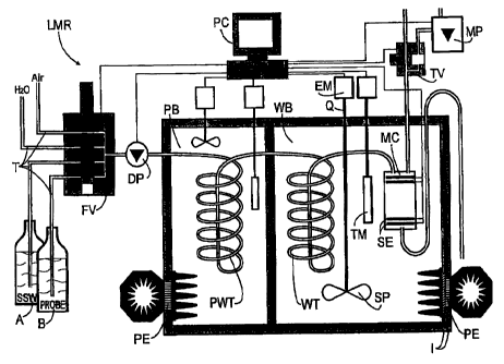
Figure 3 depicts a conductivity-reference-measuring site LRM as a preferred
arrangement for practicing the method according to the invention. The LRM is
provided with a
water bath WB and a separate advance bath PB. In the advance bath PB which may
be
heated as well as cooled by a Peltier element there is provided a preheat
exchanger PWT for
temperature adjustment between a sample PROBE taken from a sample bottle B (or
standard
sea water SSW from a vial A for calibration) and the water bath WB. In the
water bath WB a
measuring cell MC is positioned behind a main heat exchanger WT. The measuring
cell is
provided with four strip electrodes SE for measuring the changing values of
current and
voltage. Almost all media flows are fed by a dosage pump DP and flow through
hoses T by
way of a four-way valve FV acting as a distributor. Pressurized air required
for evacuating the
measuring cell MC is generated by a diaphragm pump MP as needed and is fed
into the
measuring cell MC by way of a two-way valve TV. The electrical conductivity K
is measured in
the measuring cell MC at a fully automatically balancing precision bridge (not
shown) by
means of a computer PC. Furthermore, there are provided in the water bath WB a
precision
thermometer TM for measuring the temperature 'B of the water bath and a
rotation-controlled
stirring propeller Q with a propeller SP similar to a ship's screw for
controlling the temperature
drift a by way of the mean input heating power Phm. In the embodiment shown,
it is the
commercially available thermometer "SBE3plus" of the "Seabird" company, which
because of
its stability drifts less than 1 mK during the course of a year and which
satisfied the
requirements without any problems. The stirring propeller Q is provided with
an electric motor
EM arranged outside of the water bath and counteracts a continually cooling
Peltier element
PE which for increasing its heat resistance R is provided with an insulation I
similar to the
water bath WB.
Attomey Docket 010482-US -23-
CA 02370154 2001-10-30
In the selected embodiment the stirring propeller Q has an operating range
between 3
W and 5 W and, hence, a working point at 4 W. Considering the relationship
between
temperature and heat current (d'/dt = P/Cw) and the predetermined limit and
material values
the heat current balance may be balanced with 1 W. If .5 W is reserved for
the heat current
of the ambient temperature'L may now deviate from the water bath temperature'B
by 1 K
without the temperature drift a taking on impermissibly high values. At these
values, the total
resulting heat resistance is 2 K/W. If the resistance of the insulation I of
Peltier element PE
and heat exchanger WT is 7 K/W the insulation of the bath must be 2.8 K/W. To
this end the
resistance value may, if necessary, have to be increased.
From the relationship mentioned supra it is possible with the maximum
permissible
temperature drift c4õaX = d'/dt as default and knowing the resulting heat
capacity Cwe of the
water bath WB (Vw = Cws) to calculate the tolerable residual error of the heat
current Prest to be
balanced. For instance, aax = 7 K/s and Cwa = 67 = 103 Ws/K for a water bath
of a volume
Vw = 161 and a specific Cws value for water of 4.2 = 103 Ws/(1 K) result in a
power of Prest = .47
W. At an improved heat resistance Rwi = 1.2 K/W of the water bath according to
the equation
0' = R= P the ambient temperature'L may now deviate from the bath temperature
'B by .56 K
without the control having to intervene.
List of formulas and reference characters
A vial
B sample bottle
Cwe heat capacity of the water bath
Cw heat capacity
Cws specific heat capacity
DP dosage pump
EM electric motor
FF form factor
I insulation
Attomey Docket 010482-US -24-
CA 02370154 2001-10-30
K15 standard value
KF calibration error
Kt1r2 calibration points in time
LRM conductivity reference site
Mt2...6 measuring time points
MC measuring cell
MP diaphragm pump
PB advance bath
PC personal computer
PE Peltier element
Pges total heat current
PH heating power
PHm mean heating current
Pi heat current from the vicinity
Pk cooling power
PP heat flow through the sample
PR kinetic stirring power
Prest residual heat current
Prestmax maximum residual heat current
Pw heat current
PROBE liquid sample
PWT advance heat exchanger
Q stirring propeller
R heat resistance
S salinity
Ss1, s2, ss individual measurement
SE strip electrode
SP ship's screw propeller
SSW standard sea water
t time
T hose
TM thermometer
Attomey Docket 010482-US -25-
CA 02370154 2008-03-10
52823-1
tv time interval for filling/measuring
TV two-way valve
WB water bath
WT heat exchanger
P temperature of sample
B temperature of bath
0',,m maximum permissible measurement error
a temperature drift
Um maximum permissible temperature drift
K electrical conductivity
T time constant of the measuring cell
-26-