Note: Descriptions are shown in the official language in which they were submitted.
CA 02370354 2005-07-27
1
Method for cross-direction profiling of a paper or board web in a nip.
The invention relates to a method for cross-direction profiling of a paper or
board web
in a nip.
The method according to the invention can be employed in a nip formed between
a
backing roll and a loading roll. The loading roll comprises a stationary
support
structure framework and a flexible mantle running about said structure, as
well as a
loading member adapted between the inner surface of said flexible mantle and
said
support structure so as to permit the flexible mantle to be loaded against
said backing
roll. The loading member itself may serve as a piston being adapted into a
cylinder in
which case a pressure medium acts directly on said loading member.
Alternatively,
the loading member may be actuated by separate loading cylinders adapted
between
the loading member and the stationary support structure. The loading member is
generally actuated by means of two rows of loading cylinders extending over
the
cross-machine direction and being displaced at a distance from each other in
the
machine direction. With two loading cylinders displaced at a distance from
each
other in the machine direction it is possible to make machine direction
profiling of the
web.
In the latter situation, the cross-machine direction profiling of a paper or
board web in
the nip is implemented in the state-of-the-art embodiments so that the loading
member
is actuated at different pressure levels applied to the pairs of loading
cylinders
displaced at a distance from each other in the cross-machine direction. When a
higher
pressure is applied on the loading member at one of the cylinder pairs, the
loading
member will slightly bend at said cylinder pair consequently loading the
running web
with a higher nip pressure at said point.
EP patent publication 0777 012 discloses a pressure roll comprising a
stationary
support structure and an hose mantle running thereabout supported on the
support
CA 02370354 2001-10-12
WO 00/63491 PCT/FI00/00319
2
structure by means of at least one loading member which is adapted to be
compressible against the inner surface of said hose mantle and is at least
partially
hydrodynamically lubricated. The loading member itself serves as a piston
provided with a pressure chamber which piston is adapted into a cylinder. The
load-bearing surface of the loading member, is provided with at least one row
of
discrete oil inlets parallel to the roll axis, of which oil inlets at least a
portion are
fed with a pressure medium not communicating with the pressure medium that is
passed to the pressure chamber of the loading member. Each of the oil inlets
is
provided with a flow-restricting bore through which oil enters onto the load-
bearing surface of the loading member.
The goal of the invention disclosed in the cited EP patent publication 0 777
012 is
to provide in all circumstances the load-bearing surface of the loading member
with a supply of fresh and cooled lubricating oil, whereby a maximally uniform
machine direction temperature profile is attained on the load-bearing surface
of
the loading member. The hydraulic oil passed into the pressure chamber of the
loading member that urges the loading member toward the backing roll will warm
up due to the energy input of the loading action and, as the same oil is also
passed
via a capillary duct onto the surface of the loading member, its lubrication
qualities are already degraded. When the lubricating oil is passed onto the
load-
bearing surface of the loading member, it forms an oil film between the load-
bearing surface of the loading member and the imier surface of the hose
mantle,
thus passing with the moving hose mantle to the trailing side of the load-
bearing
surface. As the lubricating oil is subjected to continuous warming-up toward
the
trailing side of the load-bearing surface, the temperature profile of the load-
bearing surface will become nonuniform. This problem is solved according to
the
cited EP publication by arranging in addition to said row of capillary ducts
cormnunicating with the pressure chamber of the loading member at least one
other row of capillary ducts, whereby the latter capillary ducts are arranged
to
cormnunicate with a separate feed channel which is formed into the loading
member aligned parallel to the axis of the hose mantle roll and which feed
channel
is fed from a separate pressure medium source. Thus, the second row of
capillary
CA 02370354 2001-10-12
WO 00/63491 PCT/F100/00319
3
ducts allows the load-bearing surface of the loading member to be flushed in
all
circumstances with fresh and cooled lubricating oil, whereby the lubricating
qualities of the oil film are improved and the machine direction temperature
profile over the load-bearing surface of the loading member can be made more
uniform.
The cited EP patent publication 0 777 012 also teaches that these capillary
ducts,
which form a row in the cross-machine direction and are connected to a
separate
pressure medium source, may be arranged into groups of desired size, whereby
the lubricating oil feed ducts of the groups may be equipped with control
valves.
Thus, the pressure and/or flow of the lubricating oil fed to each group can be
controlled separately. In this fashion, the pressure roll may be adjusted to
meet the
needs of the actual operating conditions. Obviously, the teaching must be
understood to mean that when the lubricating oil channels communicating with a
pressurized fluid chamber of the loading member fail to provide a uniform and
sufficiently thick lubricating oil film between the loading member and the
hose
mantle, the lubrication may be intensified by feeding additional fresh
lubricating
oil between the loading member and the envelope through separate lubricating
oil
channels.
WO patent publication 98/04844 discloses a roll for pressing a web. The roll
has a
stationary axial shaft with a mantle rotating about the same and having
loading
elements adapted thereto that support the mantle on the axial shaft and serve
to
load the mantle against a backing roll. Normally, each loading element loads
the
mantle via an individual back-up element which is connected to the loading
element and has a lubricating oil pocket thereon. However, a small gap remains
between the adjacent back-up elements through which lubricating oil can escape
from the nip formed between the inner surface of the mantle and the back-up
elements. At these gaps, the pressure of the lubricating oil may drop to zero,
which can be seen as a deformation of the mantle of the roll. To avoid this
problem, there is adapted a sealing list between the back-up elements and the
inner surface of the mantle, the list extending over a plurality of loading
elements
CA 02370354 2005-07-27
4
in the axial direction of the roll and, preferably, over the entire axial
length of the roll.
The lubricating oil pockets are formed on the sealing list rather than on the
back-up
elements. This arrangement makes it possible to eliminate the gaps between
individual back-up elements and to apply a uniform lubricating oil pressure
distribution on the inner surface of the mantle over the entire axial length
of the roll.
The roll has a fiber-reinforced plastic covering, that is, a composite mantle,
with a
thickness of about 15-20 mm, which means that also such a mantle may deformate
due to lubricating oil pressure.
In accordance with one aspect of the present invention, there is provided a
method for
cross-direction profiling of a paper or board web in a nip formed between a
backing
roll and a loading roll, which loading roll is comprised of a stationary
support
structure and, adapted to run about the same, a flexible mantle supported by
its inner
surface on the support structure by means of at least one supporting member
serving
to press the flexible mantle against the backing roll, and which loading roll
further
includes at least one essentially axially aligned row of discrete pressure
medium feed
points, whereby a pressure and/or flow rate controlled flow of pressure medium
is fed
through the feed points of the at least one row against the inner surface of
the mantle,
wherein the pressure medium fed through the feed points is used for
controlling the
cross-machine direction profiling of the paper or board web passing through
the nip.
A loading roll implemented by virtue of the method according to the invention
requires at least one row of pressure medium feed points that are aligned
essentially
parallel to the axis of the roll and are displaced apart from each other so
that each feed
point can be used for feeding a pressure and/or flow-rate controlled flow of
pressure
medium against the inner surface of the mantle of the loading roll. This row
of
pressure medium feed points may be located either on the loading member of the
loading roll or, alternatively, just in front of the loading member relative
to the
rotation direction of the mantle of the loading roll. The invention is based
on the idea
that a prior-art
CA 02370354 2005-07-27
4a
construction is controlled in an unorthodox manner contrary to the teachings
of the
prior art. According to the prior-art teaching, a lubrication medium
arrangement
comprising discrete feed points is controlled so that a maximally uniform
lubrication
medium film is formed between the roll mantle and the loading member. In
contrast,
the goal of the present invention is to particularly establish between the
mantle of the
roll and the loading member a nonuniform profile of the lubrication medium
film in
the cross-machine direction. The thickness variations of the cross-machine
direction
profile of the lubrication medium film in turn lead to a nonuniform cross-
machine
direction nip pressure profile, whereby the paper or board web is subjected to
a nip
pressure profile which is different at different cross-machine direction
points of the
nip. The invention utilizes actively a nonuniform nip pressure profile
CA 02370354 2001-10-12
WO 00/63491 PCT/FI00/00319
generated by means of a nonuniform lubrication medium film thickness profile
for
cross-machine direction profiling of a paper or board web in a nip.
The minimum zone spacing in the cross-machine direction is determined by the
5 width of the discharge points of the individual lubrication medium feed
points, the
spacing between the feed points and the stiffness of the mantle of the roll.
In the
method according to the invention, the cross-machine direction profiling of
the
paper or board web may thus be carried out using a very dense zone spacing set
at, e.g., about 20 mm.
A preferred application of the method according to the invention is a calender
in
which the nip is formed between a heated backing roll and a loading roll. The
method according to the invention is also applicable to a press in which the
nip is
formed between a backing roll and a loading roll. In a calender, the web
passes
through the nip between the outer surface of the mantle of the backing roll
and the
outer surface of the mantle of the loading roll. In a press, the web generally
passes
through the nip between a first fabric travelling on the outer surface of the
mantle
of the backing roll and a second fabric travelling on the outer surface of the
mantle of the loading roll. A calender and a press may also differ as to the
shape
of the loading member forming the nip and the length of the nip.
The SymBeltTM type of hose rolls produced by applicant have a hydrodynamic
lubricating oil pocket made on the sliding face of the loading member. In a
calender application, the lubricating oil pocket generally comprises only one
pocket extending over the entire width in the cross-machine direction. In a
press,
the sliding face of the loading member generally has an individual lubricating
oil
pocket formed separately at each lubricating oil feed point, thus requiring
the
loading member to have a plurality of lubricating oil pockets made thereto
over
the entire length in the cross-machine direction.
CA 02370354 2001-10-12
WO 00/63491 PCT/FI00/00319
6
In the following the invention will be described by making reference to the
appended drawings. whereby the details thereof are not understood to limit the
scope of the invention, in which diagrams
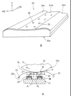
FIG. 1A shows a schematic cross-sectional view of a nip in which the method
according to the invention can be utilized;
FIG. 1 B shows an axonometric view of one loading member of the nip; and
FIG. 2 shows a cross-sectional view in the cross-machine direction at the
lubricating oil ducts of the loading member illustrated in FIG. 1B.
FIG. 1A shows schematically a cross sectional view of a nip formed between a
backing roll 10 and loading roll 20, while FIG. 1 B shows an axonometric view
of
a loading member, that is, a loading shoe 23 adapted to the interior space of
the
loading roll 20. The mantle of the loading roll 20 is formed by a so-called
hose
mantle 22 and, accordingly, the loading roll 20 will later in the text be
called a
hose mantle roll 20. In FIG. 1A, the direction of rotation of the backing roll
10 is
denoted by arrow S, and the direction of rotation of the mantle 22 of the
loading
roll is denoted by arrow S2. Furthermore, the directions in FIG. 1B are
denoted as
the machine direction MD, that is, the travel direction of the web, the cross-
machine direction CD and the web thickness direction Z.
The hose mantle roll 20 comprises a stationary support structure 21 and a hose
mantle 22 adapted to run about the same. The flexible hose mantle 22 is
supported
by its inner surface 22a on a loading shoe 23 extending over the width of the
machine in the cross-machine direction CD. The loading shoe 23 in turn is
supported on the support structure 21 of the hose mantle roll 20 by two
loading
cylinder rows 27,28 aligned at a distance from each other in the machine
direction
MD and extending over the width of the machine in the cross-machine direction
CD. The loading shoe 23 and, hence, hose mantle 22 may be loaded against the
backing roll 10 by adjusting the loading force imposed by the cylinders 27,
28.
CA 02370354 2001-10-12
WO 00/63491 PCT/FI00/00319
7
The load-bearing surface 24 of the loading shoe 23 is formed so as to form an
extended nip N with the backing roll 10. The load-bearing surface 24 of the
loading shoe 23 is comprised of three areas 24a,24b,24c. The first area 24a
forms
the leading edge of a hydrodynamic web support area, the second area 24b forms
a hydrostatic lubricating oil pocket and the third area 24c forms the trailing
edge
of a hydrodynamic web support area. The lubricating oil pocket 24b is formed
into a recess between the leading edge area 24a and the trailing edge area 24c
adjoining the recess. The radiuses of curvature in the portions of the leading
edge
area 24a and the trailing edge area 24c adjoining the lubricating oil pocket
24b are
made compliant with the radius of curvature of the backing roll 10. The
flexible
hose mantle 22 will pass between the load-bearing surface 24 of the loading
shoe
23 and the outer surface 10b of the mantle of the backing roll 10 so as to
form an
extended nip N.
To the lubricating oil pocket 24b of the loading shoe 23, from the underside
23a of
the loading shoe, there is adapted a first row of ducts 25 disposed at a
distance
from each other and extending over the cross-machine direction CD, the ducts
permitting lubricating oil to be pumped into the lubricating oil pocket 24b.
Into
the lubricating oil pocket 24b, from the underside of the loading shoe 23, is
also
adapted to pass a second row of ducts 26 disposed at a distance from each
other,
the ducts permitting a pressure medium for the purpose of cross-machine
direction
profiling of the web to be pumped into the lubricating oil pocket 24b
independently of the lubrication medium. This second row of channels 26 is
disposed after the first row of channels 25 in the machine direction MD at a
location where the depth of the lubricating oil pocket 24b is shallower than
at the
first row of channels 25. When the pressure medium for the cross-machine
direction profiling of the web is introduced onto the load-bearing surface 24
of the
loading shoe 23 via the hydrostatic lubricating oil pocket 24b, the wear
caused by
the profile-controlling pressure medium on the hose mantle 22 is minimized.
CA 02370354 2001-10-12
WO 00/63491 PCT/FI00/00319
8
The individual ducts 26 of the second row are advantageously divided into
groups
so that in each group there is at least one duct 26, whereby the flow rate
and/or
pressure of the pressure mediuin flow into each group can be controlled
individually. This can be accomplished so that each group is fed from a
separate
pressure medium source having a controllable flow rate and/or pressure.
Another
alternative embodiment is shown in FIG. 2 illustrating a sectional view in the
cross-machine direction CD at the lubricating oil ducts 26 of the loading shoe
23
illustrated in FIG. 1B. The embodiment shown in FIG. 2 uses a cormnon-rail
feed
chamlel 30, wherefrom a manifold of channels with valves 31 are branched into
each duct 26, thus permitting the flow rate and/or pressure of the pressure
medium
being fed into the ducts 26 to be individually controlled by means of the
valves
31. In both arrangements, the pressure medium can be continually fed into each
group at a desired flow rate and/or pressure for the purpose of cross-machine
direction CD profiling of the paper or board web being passed through the nip.
When the profile control is active, at least one of the profile control ducts
26 is
used for feeding a pressure medium into the lubricating oil pocket 24b at a
pressure P i and flow rate higher than the respective pressure Po at which the
lubricating fluid is being fed into the lubricating oil pocket 24b. Hence, the
excess
pressure medium discharged from the profile control ducts 26 cannot
iinmediately
spread out into the lubricating oil pocket 24b, but rather, the excess
pressure
medium flow presses with a locally higher force the readily deformable hose
mantle 22 against the backing roll 10. Resultingly, the web at that point in
the
cross-machine direction CD is subjected to a pressing force higher than the
average pressure along the nip, thus facilitating the web profile control in
the
cross-machine direction CD. In a calender equipped with the applicant's
SymBeltT'" roll embodiment, the pressure medium is pumped into the lubricating
oil ducts 25 normally at a pressure of about 100 bar. The profile control
ducts 26
are fed with the pressure mediuin at a pressure of about 100-120 bar.
In the above-described embodiment, the loading shoe 23 is actuated by two
hydraulic cylinder rows 27,28. The invention is as well suited for use in an
CA 02370354 2001-10-12
WO 00/63491 PCT/FI00/00319
9
arrangement, where the loading shoe 23 itself acts as the piston moving in a
cylinder. The loading shoe 23 is formed so as to form a pressure chamber into
which the pressure medium can be fed in order to press the loading shoe 23
against the backing roll 10. Then, the row of lubricating oil ducts 25 exiting
in the
lubricating oil pocket 24b may be directly communicating with said pressure
chamber or, alternatively, the row of lubricating oil ducts 25 can be fed from
a
separate pressure medium source. The ducts 26 used for profiling and arranged
in
suitable groups are in all circumstances fed from a separate pressure medium
source.
While the rows of ducts 25 and 26 are in FIG. 1 drawn so as to be aligned in
two
parallel rows in the machine direction MD, they may as well be merged into a
single row without departing from the scope of the invention. The ducts 26
used
for profiling in the cross-machine direction CD are located interlaced between
the
ducts 25 used for the lubrication of the load-bearing surface 24 of the
loading shoe
23. The ducts may be ordered so that every first duct is a lubricating oil
duct 25
and every other duct is a profile control duct 26, but also other arrangements
are
possible.
In FIG. 1 is shown only one row of ducts 26 for cross-machine direction
profiling
of the web, but the invention may as well use a plurality of rows of ducts 26
arranged adjacent to each other in the machine direction MD. The ducts 26 may
form a desired pattern on the load-bearing surface 24 of the loading shoe 23.
In FIG. 1, the rows of the lubricating oil ducts 25 and the profile control
ducts 26,
respectively, are shown to discharge into the lubricating oil pocket 24b
formed on
the load-bearing surface 24 of the loading shoe 23. but this is not necessary
for the
invention. The lubricating oil ducts 25 and/or the profile control ducts 26
may as
well be arranged to discharge e.g. into recesses made on the load-bearing
surface
24 of the loading shoe 23.
CA 02370354 2001-10-12
WO 00/63491 PCT/FI00/00319
In FIG. 1 the loading shoe 23 is drawn so as to extend uniformly over the
entire
width of the machine in the cross-machine direction CD, but without departing
from the spirit of the invention, a plurality of shoe sections adjoining in an
end-to-
end fashion in the cross-machine direction CD can be used to form the loading
5 shoe 23.
In FIG. 1 A is shown an embodiment in which the hose mantle roll 20 is
equipped
with a flexible hose mantle 22, but the method according to the invention is
also
applicable to roll embodiments having their mantle 22 made from a less
resilient
10 material. For instance, the cited WO patent publication 98/04844 uses a
composite
mantle having a thickness of about 15-20 mm. Also this type of mantle may be
made deformable under the pressure of the lubricating oil, thus allowing the
use of
a composite-material mantle in lieu of the hose mantle as the roll mantle. In
all
circumstances, the mantle of the roll must have so much resilience as to be
deformable under the pressure of the oil fed into the profile control ducts.
The invention is specified in the appended claims, whereby the details of the
invention may be varied within the scope and inventive spirit disclosed
therein
from those of the exemplifying embodiment described above.