Note: Descriptions are shown in the official language in which they were submitted.
CA 02370402 2002-02-01
APPARATUS AND METHOD FOR MIXING
A GAS AND A LIQUID
BACKGROUND OF THE INVENTION
This invention relates to an apparatus and method for mixing a gas and a
liquid. In one aspect, this invention relates to an apparatus and method for
mixing a
carrier gas with an atomized liquid while in another aspect, this invention
relates to
the formation of a mixture of carrier g4s and vaporized liquid with little, if
any,
entrained droplets. In yet another aspect, the invention relates to an
apparatus and
method for applying a preservative to a perishable product.
The preservation of perishable products has been and continues to be the focus
of considerable commercial interest. By extending the shelf life of a food
product,
e.g., a baked good, considerable economic value can be added to that product.
Approaches to this end are many and varied, e.g., tight control of storage
conditions,
_packaging, post and in situ applications of preservatives, and various
combinations of
these and other techniques are known and in practice to one extent or another.
In the context of baked goods, e.g., muffins, crumpets, scones, bagels,
cookies,
breads, etc., all of these techniques are in use, e.g., frozen or refrigerated
storage,
anaerobic packaging, and the addition of preservatives either to the batter or
mix from
which the baked good is prepared, or the application of a preservative to the
fmished
baked good. With respect to the latter, the application of a small amount of
acetic
acid to a finished baked good, e.g., a crumpet, can extend the shelf life of
the baked
good from a typical 6-8 days to an extended 14-16 days (all other conditions,
e.g.,
CA 02370402 2002-02-01
2
packaging, storage conditions, etc., being equal). One problem, however, in
the
application of a preservative to a food product is to apply the preservative
in a manner
that does not interfere with the natural sensient properties of the product,
e.g., taste,
smell, texture, etc. In the case of applying acetic acid to a finished baked
product, too
much acetic acid can impart an unwanted tartness to the product.
Another problem with the application of a preservative to the finished baked
good is consistent application of the preservative in a production line
setting.
Commercially distributed baked goods, along with most other commercially
manufactured and distributed perishable goods, are made in large quantities,
and
consistency from one item to the other is important to the commercial success
of the
product line. In the case of applying acetic acid to baked goods, the amount
of acetic
acid applied to the first baked good in the production cycle should be
essentially the
same as the amount of acetic acid applied to the last item in the production
cycle (and
all items throughout that production cycle, for that matter). This can be
difficult to
control over extended periods of time due to, among other things, variations
in the
temperature of the equipment, the preparation and delivery of the acetic acid
to the
finished product, and the like.
For example, the application of acetic acid as a preservative to a finished
baked good typically begins with the conversion of liquid acetic acid to
gaseous acetic
acid. This conversion is accomplished by any one of a number of different
procedures, e.g., flash evaporation, atomization, etc., and the gaseous acetic
acid is
then transported, typically by a carrier gas, e.g., carbon dioxide, to a
treatment
chamber. Finished baked goods are fed on a batch basis to the chamber in which
they
CA 02370402 2002-02-01
y ~ }. .
3
are exposed under predetermined conditions to the acetic acid, removed from
the
chamber, and then the cycle repeats. One common problem with this technique is
that the gaseous acetic acid often has entrained within it small droplets of
liquid acetic
acid and these droplets, when deposited on the finished baked good, can
constitute an
overdose of preservative and impart a tartness to the product. The droplets
originate
from either incomplete vaporization of the acetic acid and/or as a condensate
from the
gaseous acetic acid as it is transported from a vaporization zone to the
treatment
chamber. Similar problems exist, of course, with the application of other
gaseous
preservatives to other perishable products.
SUMMARY OF THE INVENTION
According to this invention, an apparatus and method is provided for mixing a
gas and a liquid to produce a gaseous vapor of the liquid that is
substantially free of
droplets. The apparatus and method are well adapted to converting a
preservative
from a liquid to a gaseous state for application to a perishable product.
In one embodiment, the invention is an apparatus for mixing a gas and a liquid
to form a gaseous mixture substantially free of droplets, the apparatus
comprising:
A. A source of the gas;
B. A source of the liquid;
C. An atomization nozzle;
D. An antechamber;
E. An orifice plate; and
CA 02370402 2002-02-01
t y (
4
F. A mixing/separation chamber.
The atomization nozzle is in fluid communication with both the source of the
gas and
the source of the liquid, the liquid atomized by the gas within the
atomization nozzle
to form an atomized mixture of the gas and the liquid. The antechamber is (i)
in fluid
communication with the source of the gas, and (ii) in fluid communication with
and
separated from the mixing/separation chamber by an orifice plate. The orifice
plate
comprises one or more orifices through which the gas can pass from the source
of the
gas, through the antechamber, and into the mixing/separation chamber. The
atomization nozzle extends through the antechamber and the orifice plate, and
is in
open communication with the mixing/separation chamber such that the atomized
mixture of the gas and the liquid is discharged into the mixing/separation
chamber.
The mixing/separation chamber comprises a housing having an upper section
and a lower section. The upper section is in open communication with both the
atomization nozzle and the antechamber, and the lower section is equipped with
an
exit port. The atomization nozzle and orifice plate are configured to form a
mixing
zone within the upper section of the mixing/separation chamber such that as
the
atomized mixture of gas and liquid is discharged into the upper section of the
chamber, gas from the antechamber passes through the orifices of the orifice
plate so
as to impinge upon and vaporize substantially all, if not all, of the liquid
component
of the atomized mixture of gas and liquid. The vaporized mixture of the gas
and the
vaporized liquid then moves into the remainder of the chamber, i.e., the
separation
zone of the chamber, in which any residual droplets separate gravitationally
from the
CA 02370402 2002-02-01
r "~ r {
vaporized mixture. The residual or unvaporized droplets settle onto the floor
of the
chamber from which they are either removed through a drain, or vaporized if
the
appropriate conditions exist within the separation zone, e.g., the floor of
the chamber
is heated to a sufficient temperature to vaporize the droplets. The exit port
located in
5 the lower section of the mixing/separation chamber is in sealed relationship
with a
discharge conduit for the discharge of the vaporized mixture free of a
substantial
amount of residual droplets. The conduit extends from the exit port into and
is in
open communication with the upper section of the mixing/separation chamber. As
here used, "in sealed relationship" means that the discharge conduit is joined
to the
exit port in such a manner that the vaporized mixture can enter the conduit
only from
the upper section of the chamber, and it can be removed from the chamber only
by
passing through the conduit.
In another embodiment, the invention is a method for mixing a gas and a
liquid to form a gaseous mixture substantially free of droplets, the method
comprising
the steps of:
A. Separating the gas into a first gas stream and a second gas stream;
B. Mixing the first gas stream with the liquid in an atomization zone
under conditions in which the liquid is atomized by the gas to form an
atomized mixture comprising a gas component and a liquid
component, the liquid component in atomized or small droplet form;
C. Mixing the atomized mixture with the second gas stream in a mixing
zone under conditions in which the liquid component of the atomized
mixture is substantially vaporized to form a vaporized mixture of the
CA 02370402 2002-02-01
i ~!+ , =
6
gas and vaporized liquid, the vaporized mixture containing residual
amounts of the liquid in droplet form;
D. Gravitationally separating the residual liquid droplets from the
vaporized mixture in a separation zone; and
E. Recovering the vaporized mixture free of a substantial amount of
residual droplets from the separation zone.
Typically, the mixing and separation zones are within the mixing/separation
chamber
previously described.
In yet another embodiment, the invention is a mixing and separation chamber
for (i) preparing a gaseous mixture comprising (a) first and second gases, and
(b)
droplets of the second gas, and then (ii) separating the residual droplets
from the first
and second gases, the chamber comprising:
A. A housing having an upper section and a lower section, the upper
section equipped with an entry port for receiving the first gas and an
atomized mixture of the first gas and droplets of the second gas in such
a manner that the first gas and the atomized mixture are in contact with
one another upon their immediate entry into the upper section of the
chamber, the contacting producing the gaseous mixture, and the lower
section equipped with an exit port; and
B. A discharge conduit for removing the gaseous mixture free of a
substantial amount of the residual droplets from the housing, the
discharge conduit in a sealed relationship with the exit port and
extending into the upper section of the housing.
CA 02370402 2002-02-01
1 .
7
In still another embodiment, the invention is a method of separating droplets
from a vaporized mixture comprising first and second gases and droplets of the
second gas, the method comprising the steps of
A. Providing a mixing/separation chamber, the chamber comprising:
1. A housing having an upper section and a lower section, the
upper section equipped with an entry port and the lower section
equipped with an exit port;
2. A discharge conduit for removing from the housing the
vaporized mixture free of a substantial amount of the droplets,
the discharge conduit in a sealed relationship with the exit port
and extending into the upper section of the housing;
B. Maintaining the chamber at a temperature above the vaporization
temperature of the gases of the vaporized mixture;
C. Creating the vaporized mixture in the upper section of the housing in a
mixing zone adjacent the entry port;
D. Allowing the droplets to gravitationally separate from the vaporized
mixture in a separation zone of the chamber, the droplets accumulating
in the lower section of the housing and the vaporized mixture free of a
substantial amount of the droplets circulating throughout the separation
zone; and
CA 02370402 2002-02-01
8
E. Removing the vaporized mixture free of a substantial amount of the
droplets from the housing through the discharge conduit and exit port.
In another embodiment, the invention is a method of extending the shelf life
of
a perishable product having an external surface, the method comprising the
steps of:
A. Preparing the product; and
B. Applying a vaporized preservative substantially free of droplets to the
external surface of the product, the vaporized preservative prepared by
a method comprising the steps of:
1. Separating a carrier gas into a first gas stream and a second gas
stream;
2. Mixing the first gas stream with a liquid preservative under
conditions in which the liquid is atomized by the gas to form an
atomized mixture comprising the carrier gas and the liquid
preservative, the preservative in droplet form;
3. Mixing the atomized mixture with the second gas stream under
conditions in which the liquid preservative is substantially
vaporized to form a vaporized mixture of the carrier gas, the
vaporized preservative and residual droplets of the
preservative; and
4. Separating the residual droplets from the vaporized mixture in a
separation zone, the zone comprising:
CA 02370402 2002-02-01
9
a. A housing having an upper section and a lower section,
the upper section equipped with an entry port and the
lower section equipped with an exit port;
b. A discharge conduit for removing the vaporized mixture
free of any significant amount of residual droplets from
the housing, the discharge conduit in a sealed
relationship with the exit port and extending into the
upper section of the housing, the residual droplets
gravitationally separated from the carrier gas and
preservative vapor within the housing.
The present invention is especially well adapted for mixing gaseous carbon
dioxide
with liquid acetic acid to form a gaseous mixture of carbon dioxide and acetic
acid
which is substantially free of droplets, the gaseous mixture useful as a
preservative for
perishable goods, especially baked products.
As used in this specification, "free of a substantial amount of residual
droplets" and like phrases means that whatever amount of residual droplets
that
remain in the vaporized mixture of gas (e.g., C02) and vaporized liquid (e.g.,
acetic
acid) after the mixture is recovered from the mixing/separation chamber, it is
not
enough to have a detrimental impact on the ultimate end use of the vaporized
mixture.
For example, if the residual droplets .are acetic acid, the vaporized mixture
is gaseous
CO2 (as a carrier gas) and vaporous acetic acid, and its ultimate end use is
as a
preservative for baked goods, then the amount of residual droplets in the
vaporized
CA 02370402 2002-02-01
r r .
mixture is insufficient to have a detrimental impact on the sensient
properties of the
baked goods, as perceived by a typical consumer, after the goods are treated
with the
vaporized mixture in standard fashion.
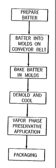
5 BRIEF DESCRIPTION OF THE DRAWINGS
FIG. 1 A is a schematic flow diagram of one embodiment of the process to
make a baked product, e.g., a crumpet.
10 FIG. 1B is a schematic flow diagram of an alternative embodiment of the
process to make a baked product.
FIG. 2 is a schematic flow diagram of one embodiment of a batch operation of
a treatment chamber.
FIG. 3 is a schematic flow diagram of an embodiment of a process for mixing
gaseous carbon dioxide with liquid acetic acid to form a vaporous mixture of
carbon
dioxide and acetic acid which is substantially free of acetic acid droplets.
FIG. 4 is a more detailed schematic flow diagram of FIG. 3.
FIG. 5 is an enlarged schematic of the mixing zone of FIG. 4.
DESCRIPTION OF THE PREFERED EMBODIMENTS
Various embodiments of the invention are described by reference to the
drawings in which like numerals are employed to designate like parts. Various
items
of equipment, such as fittings, valves, mountings, pipes, sensors, monitoring
equipment, wiring and the like have been omitted to simplify the description.
CA 02370402 2002-02-01
Y , r f t
11
However, such conventional equipment and its use are known to those of skilled
in
the art, and can be employed as desire. Moreover, although the invention is
described
below in the context of mixing carbon dioxide and acetic acid for application
as a
preservative to baked goods, those skilled in the art will recognized that the
invention
has applicability to many different gas and liquid combinations for a wide
variety of
uses.
FIG. 1 A is a broad description for the preparation of conunercial quantities
of
a baked good, e.g., a crumpet. Batter is prepared, and then it is poured into
molds that
are either carried on or form a part of a continuous conveyor belt. The belt
moves the
batter through a baking zone in which the batter is fully baked. Upon leaving
the
baking zone, the crumpet is demolded, typically onto another conveyor belt.
The demolded crumpets are then conveyed through a cooling tunnel after
which the crumpets are at a temperature appropriate for packaging (e.g., room
temperature or slightly above). However according to one embodiment of this
invention, before packaging the crumpets pass through a treatment chamber in
which
a preservative is applied to their external surface. In another embodiment and
as
described in FIG. 1B, the cooling and preservative stations are reversed,
i.e., after
demolding the crumpets are treated with a preservative, cooled and then
packaged.
The treatment chamber is essentially a movable hood in combination with a
base. The hood can be manipulated, e.g., raised and lowered, in such a manner
that
goods to be treated are easily inserted and removed from the volume defined by
the
hood and base when both are in a closed relationship with one another. The
hood is
equipped with an entry port for receiving the vaporized mixture. The treatment
CA 02370402 2002-02-01
12
chamber base is typically a section of conveyor belt beneath which is a
platen. The
hood closes over the base in a manner that will permit a vacuum to be drawn
within
the chamber. In another embodiment, the treatment chamber is separate and
apart
from the conveyor belt, and this requires a transfer of the crumpets from the
belt and
into the chamber for treatment.
FIG. 2 describes a typical batch operation. The chamber of this example
operates on a 25-30 second cycle. First the hood is raised and the crumpets
are
transferred from an indexing conveyor onto a conveyor within the chamber. Next
the
hood is lowered and sealed against the treatment chamber base, typically a
platen
underneath the conveyor on which the crumpets are positioned. The seal between
the
hood and the platen is sufficient to allow a vacuum to be drawn. The
atmosphere,
e.g., air, in the sealed chamber is evacuated, the preservative fed into the
evacuated
chamber to -coat onto and/or penetrate into the external surface of the
crumpets, the
excess preservative exhausted, the hood raised, the treated product removed,
and then
the cycle repeated. The construction and operation of various embodiments of
the
treatment chamber are well known to those skilled in the art.
The preservative applied to the crumpets in the treatment chamber is acetic
acid. This acid is in the gaseous state when applied, and it is admixed with a
carrier
gas, e.g., gaseous carbon dioxide. The amount of acetic acid applied to the
crumpets
is important to both the effectiveness of the preservative and the sensient
properties of
the crumpet. Not enough acetic acid, and the preservative has little, if any,
effect.
Too much acetic acid, and the preservative imparts an unwanted tartness to the
crumpet. While the amount of preservative applied to the crumpet will vary
with a
CA 02370402 2002-02-01
} ~ r p .
13
host of considerations, e.g., the nature of the baked item, the length of time
to which
the baked item is exposed to the preservative, conditions (e.g., pressure,
temperature,
carrier gas, etc.) of the treatment chamber, and the like, typically acetic
acid in the
amount of about 0.25 weight percent based upon the combined weight of the
acetic
acid and carbon dioxide is sufficient when applied under vacuum conditions
(e.g., -90
to -100 kpa) over a period of about 10-15 seconds. In order to maintain
consistency
over an extended period of production, the gaseous acetic acid should be
substantially
free of acetic acid droplets. These droplets are of minute size (e.g., one
micron or
less), and the total droplet content of the treatment gas (carbon dioxide plus
vaporous
acetic acid) is typically less than about 1, preferably less than about 0.25,
weight
percent.
FIG. 3 provides a generic description of the process by which the acetic acid
is
diluted and vaporized with, and carried by, carbon dioxide. In a typical
embodiment,
commercially available liquid carbon dioxide is used as the carbon dioxide
source. It
is vaporized, heated and then transferred to a mass flow meter in which it is
divided
into two streams. One stream is used to atomize liquid acetic acid drawn from
a
holding tank into a fine spray. This atomized or spray of acetic acid is then
transferred to a mixing/separation chamber in which it is contacted with a
second
stream of carbon dioxide. In the mixing/separation chamber, the acetic acid is
vaporized, preferably to the point that little, if any, liquid acetic acid in
spray (fme
droplet) form remains. The gaseous mixture of carbon dioxide and vaporized
acetic
acid (along with any residual acetic acid droplets) are then transferred to a
buffer tank,
and from the buffer tank to the treatment chamber.
CA 02370402 2002-02-01
, ) . .
14
The buffer tank is important to the embodiment of the invention in which the
treatment chamber is operated on a batch basis. The buffer tank serves as a
reservoir
from which the gaseous mixture of carbon dioxide and acetic acid can be
continuously received while it is only periodically discharged into the
treatment
chamber. If the treatment chamber is operated on a continuous basis, then the
buffer
tank can be eliminated, i.e., the gaseous mixture of carbon dioxide and acetic
acid can
be transferred directly to the treatment chamber.
FIG. 4 describes in more detail the process described in FIG. 3. Tank 1 holds
liquid carbon dioxide, typically at about 300 psig. Liquid carbon dioxide is
transferred to vaporizer 2 in which it is converted to a gas essentially free
of any
droplets, and then the gas is passed through pressure reduction valve 3 in
which the
pressure is dropped from 300 psig to 100 psig. The gaseous CO2 is then
transferred to
heater 4 in which it is heated to essentially the same temperature as that of
the
contents of mixing/separation chamber 23 (e.g., 140 F). Temperature control
unit 26
coordinates the temperature of heater 4 and of chamber 23. From heater 4, the
gaseous carbon dioxide at 100 psig is transferred to mass flow meter 5, which
is
controlled by flow control 6. As long as pump 7 (the utility of which is
explained
later) is in proper operation, flow control 6 allows carbon dioxide to move
from mass
flow meter 5 into pipe 8. Pipe 8 divides into pipes 9 and 10. While the amount
of
carbon dioxide each of pipes 9 and 10 will carry can vary to convenience,
typically
pipe 9 will carry about 10 weight percent and pipe 10 will carry the remaining
about
90 weight percent of the carbon dioxide. The stream of carbon dioxide passing
CA 02370402 2002-02-01
a
through in pipe 10 also passes through control valve 11 before entering mixing
antechamber 12.
Liquid acetic acid is removed from tank 13 through check valve 14 by the
action of pump 15. The liquid acetic acid moves through lines 16, valve 17
into
5 metering pump 7. If atomization nozzle 20 is operational, then the liquid
acetic acid
is fed into atomization nozzle 20 in which it is atomized with carbon dioxide
delivered to the nozzle through line 9. If atomization nozzle 20 is not
operative, then
the liquid acetic acid is returned to tank 13 by way of line 18 and check
valve 19. .
Atomized acetic acid is transferred from atomization nozzle 20 into the upper
10 section of mixing/separation chamber 23 in which it is vaporized by contact
with
carbon dioxide delivered from mixing antechamber 12 through orifice plate 21.
The
carbon dioxide delivered from line 10 into antechamber 12 passes through
pressure
reduction valve 11 in which the pressure of the carbon dioxide is reduced from
100
psig to about 5 psig. The pressure of the atomized acetic acid as delivered to
15 mixing/separation chamber 23 is also about 5 psig. The temperature,
pressure and
volume of carbon dioxide introduced into the upper section of
mixing/separation
chamber 23 is sufficient such that the atomized acetic acid is essentially
completely
vaporized upon contact with it.
Atomization nozzle 20 passes through antechamber 12 and orifice plate 21,
and it opens into the upper section of mixing/separation chamber 23.
Atomization
nozzle 20 can extend into the upper section of mixing/separation chamber 23
any
convenient length, but typically the end of the nozzle is flush with or
extends only a
short distance beyond orifice plate 21.
CA 02370402 2002-02-01
, '. = .
16
Referring to FIG. 5, orifice plate 21 separates antechamber 12 from the upper
section of mixing/separation chamber 23, and it encircles the lower end of
atomization nozzle 20. Typically, orifice plate 21 is located in the entry
port of
chamber ceiling or top wall 29, and it is angled in such a manner that
orifices 22 are
slanted in the direction of atomized mixture spray 24. The number, size and
position
of the orifices in the orifice plate can vary to convenience. In a preferred
embodiment,
orifice plate 21 is heated.
Carbon dioxide gas moves under a positive pressure from antechamber 12
onto spray 24, which is discharged from the end of atomization nozzle 20. The
area
in the upper section of mixing/separation chamber 23 in which carbon dioxide
gas 22a
impinges upon spray 24 is the mixing zone of the chamber. The remainder of
mixing/separation chamber 23 is the separation zone, which includes virtually
all of
the lower section of the chamber. Within the mixing zone, the atomized acetic
acid is
vaporized into gaseous acetic acid and residual acetic acid droplets.
Referring again to FIG. 4, the residual acetic acid droplets separate
gravitationally from the mixture of gaseous carbon dioxide and acetic acid as
this
mixture circulates about the separation zone of chamber 23. Eventually the
residual
acetic acid droplets collect on floor 25 of chamber 23. In a preferred
embodiment,
floor 25 is heated to promote evaporation of the collected residual acetic
acid droplets.
Alternatively or in combination with the heated floor, the residual acetic
acid droplets
are continuously or periodically withdrawn from chamber 23 through drain 30.
Mixing/separation chamber 23 is made of any conventional material, is well
insulated, and is constructed to hold a positive pressure, e.g., between about
5-20 psig.
CA 02370402 2002-02-01
. l r .
17
Chamber 23 is equipped with a temperature sensor (not shown) which is
connected to
temperature control 26 which in turn is connected to heater 4. Temperature
control 6
adjusts heater 4 to raise the temperature of the carbon dioxide fed into
antechamber 12
so as to maintain a desired temperature, e.g., 140 F, in mixing/separation
chamber 23.
Chamber 23 is also equipped with a pressure sensor and pressure relief valve
(both of
which are not shown). Chamber 23 can also be equipped with a pressure sensor
(not
shown) that can relay information to pump 7 and/or mass flow meter 5.
Despite the effectiveness of the design of the mixing zone, some small amount
of residual droplets of acetic acid usually pass into the separation zone of
chamber 23.
This mixture of gaseous carbon dioxide and acetic acid and residual acetic
acid
droplets is under a positive pressure and as such, it disburses throughout the
internal
volume of chamber 23 (except the mixing zone, of course, which itself is under
positive pressure from both the mixture ejected from the atomization nozzle
and the
carbon dioxide ejected from the antechamber). This positive pressure
eventually
forces the gaseous acetic acid free of a substantial amount of the residual
droplets
through entrance port 27, into and though exit conduit 28, and eventually out
of
chamber 23. Since entrance port 27 of discharge conduit 28 is located in the
upper
section, preferably near ceiling 29 of chamber 23, most, if not all, of the
residual
droplets of acetic acid have separated from the gaseous mixture due to the
influence
of gravity. These droplets will condense on the internal walls of chamber 23
and the
external walls of exit conduit 28, eventually collecting on floor 25.
Because the vaporization of liquid acetic acid with gaseous carbon dioxide is
conducted on a continual basis while the application of the gaseous mixture of
carbon
CA 02370402 2002-02-01
, , .
18
dioxide and vaporous acetic acid is applied to the perishable product on a
batch basis,
buffer tank 31 is employed. The gaseous mixture discharged from exit conduit
28 is
transferred to buffer tank 31 by line 32 on a continuous basis. Line 32 is
equipped
with a pressure sensor (not shown) that relays pressure information to
pressure control
33 which in turn feeds pressure information to check valve 11. If pressure in
line 32
builds beyond a predetermined set point, this information is relayed to
pressure
control 33, which in turn closes check valve 11, thus stopping flow of carbon
dioxide
into mixing chamber 12.
Buffer tank 31 is designed to hold a positive pressure of the gaseous mixture
of carbon dioxide and vaporous acetic acid, and this pressure is, of course,
less than
that of line 32 so that the gaseous mixture continuously flows into buffer
tank 31 from
mixing/separation chamber 23. As treatment chamber or hood 34 requires a
gaseous
mixture for treatment of perishable product (not shown), the gaseous mixture
is
transferred from buffer tank 31 through line 35 into treatment chamber 34. The
transfer is a result of both the push of the positive pressure in tank 31 and
the pull of
the vacuum in treatment chamber 34. A regulator (not shown) controls the
amount of
gaseous mixture transferred from buffer tank 31 to treatment chamber 35.
Typically,
buffer tank 31 is designed to hold a pressure of the gaseous mixture of carbon
dioxide
and vaporous acetic acid at a volume of at least 10 times that of the vacuum
drawn in
treatment chamber 34. Typically, the pressure within the buffer tank never
drops
below 3 psig during the cycle of the treatment chamber. The buffer tank, and
all
reticulation between the buffer tank and treatment chamber, is maintained at a
temperature well above the vaporizing temperature of the acetic acid.
CA 02370402 2002-02-01
19
In another embodiment of the invention, the treatment chamber is operated at
atmospheric pressure, i.e., without a vacuum. Products that are less porous
than a
crumpet (or simply not porous) will likely benefit little from the application
of a
preservative under vacuum conditions. For such products, the chamber can be
operated at ambient or atmospheric pressure, and the transfer of the mixture
of acetic
acid and carbon dioxide from the buffer tank to the treatment chamber will be
effected
primarily, if not solely, by the positive pressure maintained in the buffer
tank.
Although the invention has been described in considerable detail through the
proceeding embodiments, this detail is for the purpose of illustration. Many
variations and modifications can be made without the departing from the spirit
and
scope of the invention as described in the appended claims.