Note: Descriptions are shown in the official language in which they were submitted.
CA 02370455 2004-10-29
COMBINED CYCLE POWER GENERATION PLANT
OPERATING MORE STABLY ON LOAD CHANGE
Background of the Invention
1. Field of the Invention
The present invention relates to a speed
control apparatus of a combined cycle power generation
plant.
As a power generation system, a combined
cycle power generation plant is known. The control of
the combined cycle power generation plant is achieved
by a gas turbine control system. A control logic
circuit is incorporated in the gas turbine control
system to output a gas ,turbine load instruction. Such
a known control logic circuit is shown in Fig. 1. Referring
to Fig. 1, the control logic is composed of a load
limit control circuit 101, a speed governor control
circuit 102, a temperature limit control circuit 103
and a fuel limit control circuit 104. The load limit
control circuit 101 outputs a load limit control
signal (LDCSO) 105. The speed governor control
circuit 102 outputs a speed governor control signal
(GVCSO) 106. The temperature limit control circuit
103 outputs a temperature limit control signal (TCSO)
107. The fuel limit control circuit 104 outputs a
fuel limit control signal (FLCSO) 108. Of the signal
CA 02370455 2002-02-04
- 2 -
lines in the figure, the broken line shows a digital
signal and the solid, line shows an analog signal.
A minimum level selector 109 is supplied with
the load limit control signal 105, the speed governor
control signal 106, the temperature limit control
signal 107, and the fuel limit control signal 108.
The minimum level selector 109 selects a signal with a
minimum level L< from among the above-mentioned four
control signals 105, 106, 107 and 108 and outputs it
as a final fuel control output signal (CSO control
signal) 110. The final fuel control output signal 110
is a control signal to control a fuel quantity
supplied to the gas turbine 111.
A house load operation signal 112 and an
over-speed protection control (OPC) operation signal
113 which is sent from an over-speed protection
control circuit are supplied to the load limit control
circuit 101. The house load operation signal 112 and
the over-speed protection control signal 113 are
supplied to a logical summation (OR) unit 114. A one-
shot timer 115 outputs a signal 116 for a
predetermined time pexiod in response to the signal
outputted from the logical summation unit 114. The
con rol output signal (CSO) 117 is further supplied to
the load limit control circuit 101. The control
output signal 117 is supplied to a function value unit
118 and an adder 119. The function value unit 118
CA 02370455 2002-02-04
converts the control output signal 117 into a value
signal. The adder 119 adds the control output signal
,.
117 and the value signal from the~~'function value unit
118. A signal obtained by the addition in the adder
119 is supplied to a rate-added switching unit 120 in
which a rate is switched at the same time as a
switching operation, in addition to a constant time
signal 116. The switching unit 120 outputs not an
addition value obtained by the addition in the adder
119 but a signal with a value set by a constant value
unit 121 as the load limit control signal 105 in
response to the signal 116 for the predetermined time
period.
The house load operation signal 112', a
variable value signal (SPSET) 122 which indicates the
difference of a load set value and an actual load
value, and an axis rotation frequency signal 123 are
supplied to the speed governor control circuit 1.02.
The house load operation signal 112' and the variable
value signal 122 are supplied to a proportional
integrator 124. The proportional integrator 124
integrates the variable value signal 122
proportionally to produce an integration value output
signal 126. Also, the proportional integrator 124
outputs a constant value signal of 0 which is set to a
constant value unit l25 in response to the house load
operation signal 112'. A subtractor 127 subtracts the
CA 02370455 2002-02-04
r
- 4 -
axis rotation frequency signal 123 from the
integration value output signal 1-26 to produce a
subtraction resultant signal 128. The subtraction
resultant signal 128 is amplified by an ampliffier 129
and is outputted as the above-mentioned speed governor
control signal 106.
Fig. 2 shows the control logic of the over-
speed protection control (OPC) circuit. The rotation
frequency signal 131 of the gas turbine 111, an
entrance pressure signal 132 in a middle-pressure
turbine of the gas turbine 111, a generator current
signal 133, and a generator output signal 134 are
supplied to function value units 137, 138, 139, and
140 to convert the physical quantities of them into
percentage values, respectively. A generator breaker-
on signal 135 is supplied to an inverter (NOT) unit
130. A house load operation switching signal 136 is
supplied to a one-shot timer 152. The middle-pressure
turbine entrance pressure signal 132 and the generator
current signal 133 are supplied to a subtractor 142
through the function value units 138 and 139. The
subtraction value obtained by the subtractor 142 or, a
load difference signal 143 is supplied to an adder 145
through the other function value unit 144. The
rota ion frequency signal 131 is supplied to the adder
145 through the function value unit 137. The addition
value 146 obtained by the adder 145 is supplied to a
CA 02370455 2002-02-04
r ,
- 5 -
monitor unit 147 which sends a digital signal based on
an optional setting range. The generator output
signal 134 is supplied to a logical product (AND) unit
149 through a function value unit 140, a monitor 141,
and an off-delay timer 148. The generator breaker-on
signal 135 is supplied to the logical product unit 149
through the inverter unit 130. A monitor signal 150-1
outputted from the monitor unit 147, a signal 150-2
outputted from the logical product unit 149 and a
signal 150-3 outputted from the one-shot timer 152 are
supplied to a logical summation (OR) unit 151. The
output signal outputted from the logical summation
unit 151 is the above-mentioned over-speed protection
control signal (OPC signal) 113 shown in Fig. 1 for
the OPC operation.
The over-speed protection control (OPC)
circuit has the control logic shown in Fig. 2, and is
a protection unit of the gas turbine 111 from over-
speed trip which occurs when the turbine 111 is
accelerated rapidly in case of rapid load decrease due
to load blocking-off and so on. The over-speed
protection control (OPC) circuit monitors the speed
increase rate as the output signal of the function
value unit 137 and the load difference as subtraction
value 143. When the value obtained by adding a bias
(preceding) signal based on the load difference to the
turbine rotation speed increase rate is larger than a
CA 02370455 2004-10-29
- 6 -
threshold value set in the monitor unit 147, the over-
speed control (OPC) operation is carried out to close
a turbine governor rapidly.
In the above conventional apparatus, there is
a case that the OPC operation is not carried out
because the switching to a system isolated operation
is carried out but a system load loss is small. In
such a case, the final fuel control output signal (CSO
control signal) 110 is limited based on the load limit
control signal 105 which follows a change rate which
is determined from the viewpoint of the gas turbine
protection or the control signals such as the
temperature limit control (TCSO) signal 107. Also,
the time period appears during which the axis rotation
frequency control cannot be carried out based on the
speed governor control (GVCSO) signal 106. At that
time, the phenomenon occurs where the rotation
frequency decreases largely from a rating range of the
rotation frequency, and the trip is caused. Also,
when the variable value signal 122 is determined from
the difference of a load set value and an actual load
value after the switching to the system isolated
operation, the variable value signal 122 and the
integration value signal 126 change based on an
erroneous load set value regardless of the fact that the load
is not clear. Therefore, there is a risk that the
integration value signal 126 may not keep a constant
CA 02370455 2004-10-29
_ 7 _
value and influences as an external disturbance. For
this reason, the rotation frequency control based on
the speed governor control signal 106 as the speed
governor control circuit output becomes difficult.
Moreover, even when the operation is switched to the
system isolated operation and the OPC operation is
carried out because the system load loss is large, the
rotation frequency increases for this time period and
the rotation axis inertia becomes large. In this case,
the trip is caused in the process of decreasing the
rotation frequency, if there is a large time
difference between the switching to the system
isolated operation and the OPC operation.
Therefore, to avoid improper control by which the
trip phenomenon is initiated, proper control, switching to the
system isolated operation must be carried out.
In conjunction with the above description, an
operation control apparatus is disclosed in Japanese
Laid Open Patent Application (JP-A-Heisei 9-324656).
In this reference, a minimum level selector 16a
selects a minimum one of the output signal of a fuel
limit control unit 11, the output signal of a load
limit control unit 12, and an output signal of a speed
control 13 and outputs the selected signal to a
minimum level selector 16b and an air control valve 4.
The output signal of a blade path temperature limit
CA 02370455 2002-02-04
control unit 14 and the output signal of an exhaust
gas temperature limit control unit 15 are supplied to
the minimum level selector 16b. The minimum level
selector 16b selects a minimum one of the output
signal of a blade path temperature limit control unit
14, the output signal of an exhaust gas temperature
limit control unit l5, and the output signal of the
minimum level selector l6a and outputs the selected
signal to a fuel control valve 3.
Summary of the Invention
Therefore, an object of the present invention
is to provide a combined cycle power generation plant
in which a proper speed control is carried out to
prevent a trip.
Another object of the present invention is to
provide a combined cycle power generation plant in
which proper speed control is carried out on the
switching to a system isolated operation.
In an aspect of the present invention, a
combined cycle power generation plant includes a gas
turbine operating in response to a turbine control
signal, and a speed control apparatus which outputs
the turbine control signal to the gas turbine based on
a speed governor control signal for a first time
period after an operation of the plant is switched to
a system isolated operation. The speed governor
CA 02370455 2004-10-29
- 9 -
control signal is a signal for speed control of the
gas turbine, and a switching signal is generated when
the operation of the plant is switched to the system
isolated operation.
The speed control apparatus may include a
speed governor control circuit, a plurality of limit
control circuits and a minimum signal selector. The
speed governor control circuit generates the speed
governor control signal. The plurality of limit
control circuits generates control signals for limit
controls to the gas turbine, respectively. The
minimum signal selector selects the speed governor
control signal from among the speed governor control
signal and the control signals for the first time
period as a signal with the lowest level.
In this case, it is desirable that at least
one of the plurality of limit control circuits outputs
the control signal in response to the switching signal
to have a predetermined level higher than the lowest
level for a second predetermined time period including
the first time period.
In this case, the limit control circuit
includes a load limit control circuit for maximum
output limit control of the gas turbine. The load
limit control circuit may include a one-shot timer, a
constant value generating unit and a switching unit.
The one-shot timer generates a first timer signal for
CA 02370455 2004-10-29
- 10 -
the second predetermined time period in response to
the switching signal. The constant value generating
unit generates a first constant value signal. The
switching unit outputs the first constant value signal
in response to the first timer signal as the control
signal.
The limit control circuit may include a
temperature limit control circuit for maximum
temperature limit control of the gas turbine. In this
case, the temperature limit control circuit may
include a one-shot timer, a constant value generating
unit and a switching unit. The one-shot timer
generate a second timer signal for the second
predetermined time period in response to the switching
signal. The constant value generating unit generates
a second constant value signal. The switching unit
outputs the second constant value signal in response
to the second timer signal as the control signal.
Also, the limit control circuit may include a
fuel limit control circuit for maximum fuel limit
control of the gas turbine. In this case, the
temperature limit control circuit may include a one-
shot timer, a third constant value generating unit and
a switching unit. The one-shot timer generates a third
timer signal for the second predetermined time period
in response to the switching signal. The third
constant value generating unit generates a third
CA 02370455 2002-02-04
1 1
constant value signal. The switching unit outputs the
third constant value signal in response to the third
timer signal as the control signal.
Also, the speed governor control circuit may
include a proportional integrator, a subtractor and an
amplifier. The proportional integrator proportionally
integrates a variable value signal to produce an
integration value signal, and the variable value
signal indicates a difference between a target load
value and an actual load value. The subtractor
subtracts an actual rotation frequency indicating the
actual rotation frequency of the gas turbine from the
integration value signal to produce a subtraction
resultant signal. The amplifier amplifies the
subtraction resultant signal and outputs the amplified
signal as the speed governor control signal.
Also, the speed governor control signal is
the signal for the speed control of the gas turbine in
a rating speed range, and the speed governor control
signal is lowered in level in response to the
switching signal. In this case, the speed governor
control circuit may include a switching unit, a
proportional integrator, a subtractor and an amplifier.
The switching unit outputs a variable value signal as
a selected signal usually and outputs a predetermined
level signal as the selected signal in response to the
switching signal, tha variable value signal indicating
CA 02370455 2004-10-29
- 12 -
a difference between a target load value and an actual
load value. The proportional integrator
proportionally integrates the selected signal to
produce an integration value signal. The subtractor
subtracts an actual rotation frequency indicating the
actual rotation frequency of the gas turbine from the
integration value signal to produce a subtraction
resultant signal. The amplifier amplifies the
subtraction resultant signal and outputs the amplified
signal as the speed governor control signal.
Also, the speed control apparatus may further
include an over-speed control circuit which generates
an over-speed control operation signal when a
difference between a value signal corresponding to an
entrance pressure signal of a middle-pressure turbine
of the gas turbine and a value signal corresponding to
a generator current is equal to or larger than a
predetermined threshold, and when the operation of the
plant is not switched to a house load operation. A
load limit control circuit may include a one-shot
timer, a constant value generating unit and a
switching unit. The one-shot timer generates a fourth
timer signal for a second predetermined time period in
response to the over-speed control operation signal,
the second predetermined time period including the
first time period. The constant value generating unit
generates a fourth constant value signal. The
CA 02370455 2004-10-29
- 13 -
switching unit outputs the fourth constant value
signal in response to the fourth timer signal as the
control signal.
In another aspect of the present invention, a
combined cycle power generation plant includes a gas
turbine, a load limit control circuit, a speed
governor control circuit and a minimum level selector.
The load limit control circuit outputs a load limit
control signal to control speed of the gas turbine.
The speed governor control circuit outputs a speed
governor control signal to control the speed of the
gas turbine. The minimum level selector selects the
speed governor control signal from among the load
limit control signal and the speed governor control
signal for a time period after switching to a system
isolated operation of the plant. The speed governor
control signal is lower than the load limit control
signal in level, and a system isolated operation
signal is generated when an operation of the plant is
switched to the system isolated operation.
In this case, the load limit control circuit
may include a first switching unit which outputs the
load limit control signal with a level higher than the
speed governor control signal in response to the
system isolated operation signal.
Also, the speed governor control signal may
be a signal with a level corresponding to a
CA 02370455 2002-02-04
- 14 -
subtraction value obtained by subtracting a rotation
frequency of the gas turbine from an integration value
of a variable value signal with respect to a reference
level, and the variable value signal indicates a
difference between a load set value and an actual load
value. The speed governor control circuit may include
a second switching unit which outputs a value with a
level lower than the variable value signal in response
to the system isolated operation signal in place of
the variable value signal.
Also, the load limit control circuit may
include a first switching unit which outputs the load
limit control signal with a level higher than the
speed governor control signal in response to the
system isolated operation signal. The speed'governor
control signal may be a signal with a level
corresponding to a subtraction value obtained by
subtracting a rotation frequency of the gas turbine
from an integration value of a variable value signal
with respect to a reference level, and the variable
value signal indicates a difference between a load set
valua and an actual load value. The speed governor
control circuit may include a second switching unit
which outputs a value with a level lower than the
variable value signal in response to the system
isolated operation signal in place of the variable
value signal.
CA 02370455 2004-10-29
- 15 -
Also, the combined cycle power generation
plant may further include a temperature limit control
circuit which may include a third switching unit which
outputs a temperature limit control signal with a
level higher than the speed governor control signal in
response to the system isolated operation signal for
the predetermined time period.
Also, the combined cycle power generation
plant may further include a fuel limit control circuit
which may include a fourth switching unit which outputs a
fuel limit control signal with a level higher than the
speed governor control signal in response to the
system isolated operation signal for the predetermined
time period.
In addition, the combined cycle power
generation plant may further include an over-speed
control logic circuit which outputs a load loss signal
as a logical product of a load difference signal and a
logical inversion of the system isolated operation
signal.
Brief Description of the Drawings
Fig. 1 is a circuit block diagram showing a
conventional combined cycle power generation plant;
Fig. 2 is a circuit block diagram showing a
conventional over-speed protection control (OPC)
operation apparatus;
CA 02370455 2002-02-04
- 16 -
Fig. 3 is a circuit block diagram showing a
combined cycle power generation plant according to a
first embodiment of the present invention;
Fig. 4 is a graph showing a relation of time
and rotation frequency of a gas turbine;
Fig. 5 is a graph showing a relation of time
and control signals;
Fig. 6 is a circuit block diagram showing the
combined cycle power'generation plant according to a
second embodiment of the present invention;
Fig. 7 is a circuit block diagram showing the
combined cycle power generation plant according to a
third embodiment of the present invention;
Fig. 8 is a circuit block diagram showing the
combined cycle power generation plant according to a
fourth embodiment of the present invention;
Fig. 9 is a circuit block diagram showing the
combined cycle power generation plant according to a
fifth embodiment of the present invention; and
Fig. 10 is a circuit block diagram showing
the combined cycle power generation plant according to
a sixth embodiment of the present invention.
Description of the Preferred Embodiments
A combined cycle power generation plant of
the present invention will be described below in
detail with reference to the attached drawings.
CA 02370455 2002-02-04
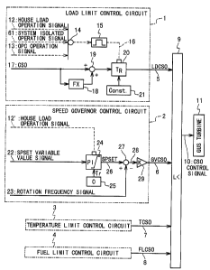
Fig. 3 shows the combined cycle power
generation plant according to the first embodiment of
the present invention. Referring to Fig. 3, the
combined cycle power generation plant in the first
embodiment is composed of a speed control apparatus
and a gas turbine 11. The speed control apparatus
outputs a CSO control signal as a fuel supply control
signal to the gas turbine ll. The gas turbine 11 has
a fuel supply contro7:.valve (not shown) which is
controlled based on the CSO control signal.
The speed control apparatus is comprised of a
load limit control circuit 1, a speed governor control
circuit 2, a temperature limit control circuit 3, a
fuel limit control circuit 4 and a minimum level
selector (minimum level selector) 9. The load limit
control circuit 1 generates a load limit control
signal (LDCSO) 5 for maximum output limit control to
the gas turbine 11. The speed governor control
circuit 2 generates a speed governor control signal
(GVCSO) 6 for speed control of the gas turbine 11.
The temperature limit control circuit 3 generates a
temperature limit control signal (TCSO) 7 for maximum
temperature limit control to the gas turbine 11. The
fuel limit control circuit 4 generates a fuel limit
control signal (FLCSO) 8 for fuel limit control to the
gas turbine 11. Of the signal lines shown in the
figure, the broken line shows a digital signal line
CA 02370455 2002-02-04
- 18 -
and the solid line shows an analog signal line.
The load limit control circuit 1 is comprised
of a logical summation (OR) unit 14, a one-shot timer
15, a function value unit 18, adder 19, a constant
value unit 2l, and a switching unit 20. A house load
operation signal 12, a system isolated operation
signal 61 and an over-speed protection control (OPC)
operation signal 13 are supplied to the logical
summation unit 14. The house load operation signal 12
is generated when the operation of the plant is
switched to a house load operation. The system
isolated operation signal 61 is generated when the
operation of the plant is switched to a system
isolated operation. An over-speed protection control
(OPC) operation signal 13 is supplied from an over-
speed protection controller (OPC). A one-shot timer
15 outputs a time period signal 16 active for a
predetermined time period in response to on a signal
outputted from the logical summation unit 14.
In addition, a control output signal (CSO
signal) 17 is supplied to the function value unit 18
and the adder 19. The adder adds the CSO signal 17
and a value signal obtained from the function value
unit 18 and supplies tha addition resultant signal to
the switching unit 20. The constant value unit 21
outputs a constant value signal. The switching unit
20 usually outputs the addition resultant signal.
CA 02370455 2002-02-04
_ lg _
However, the switching unit 20 selects and outputs the
constant value signal from the constant value unit 21
in response to the time period signal 16. The output
signal from the switching unit 20 is supplied to the
minimum level selector 9 as a load limit control
(LDCSO) signal.
The speed governor control circuit 2 is
comprised of a proportional integrator 24, a constant
value unit 25, a subtractor 27 and an amplifier 29. A
SPSET variable value signal 22 and a constant value
signal (0 value signal in this example) are supplied
to the proportional integrator 24. The variable value
signal 22 is determined from the difference of a load
set value and an actual load value. The proportional
integrator 24 proportionally integrates the variable
value signal 22 usually to produce an integration
value signal 26. However, the proportional integrator
24 does not proportionally integrates the variable
value signal but outputs the constant value of 0 from
the constant value unit 25 as the integration value
signal 26 in response to the house load operation
signal 12'. The proportional integrator 24 outputs
the integration value signal to the subtractor 27. A
rotation frequency signal 23 indicating the rotation
frequency of the gas turbine 11 is also supplied to
the subtractor 27. The subtractor 27 subtracts the
rotation frequency signal 23 from the integration
CA 02370455 2002-02-04
_ 20 _
value signal 26 to produce a subtraction resultant
signal 28 which is supplied to the amplifier 29. The
amplifier 29 amplifies the subtraction resultant
signal 28 and output the amplified signal as a speed
governor control signal 6 to the minimum level
selector 9.
The temperature limit control circuit 3 and
the fuel limit control circuit 4 output the
temperature limit control signal (TCSO) 7 and the fuel
limit control signal (FLCSO~ 8 to the minimum level
selector 9.
The minimum level selector 9 selects a signal
with the minimum level L< from among the above-
mentioned four control signals 5, 6, 7 and 8, and
outputs it as the final fuel control output signal
(CSO control signal) 10. The final fuel control
output signal 10 is a control signal to control the
supply of fuel to the gas turbine 11.
As described above, on a usual load operation,
the load limit control signal 5 fo3lows the value
obtained by adding a bias value determined by the
function value unit 18 to the control signal 17 by the
adder 19 through the switching unit 20. On the house
load operation, the load limit control signal 5 is
changed to a tracking value set by the constant value
unit 21 by the switching unit 20 for a predetermined
time period which is set by the one-shot timer 15 in
CA 02370455 2002-02-04
- 21 -
response to the house load operation signal 12. The
same operation is carried out in response to the over-
speed protection con rol signal 13 or the system
isolated operation signal 61.
Fig. 4 shows a relation of rotation frequency
and time on the system isolated operation when the
over-speed protection control operation is not carried
out: The system load decreases rapidly when the
operation of the plant is switched to the system
isolated operation at time T0. For this reason, the
rotation frequency increases rapidly from an initial
rating rotation frequency r0 and the rotation
frequency reaches a maximum value at time T1. To
decrease the rotation frequency, the subtraction
resultant signal 28 outputted from the subtractor 27
decreases rapidly. Also, the speed governor control
signal 6 decreases rapidly, so that the final fuel
control signal (CSO) 10 decreases, although the load
limit control signal 5 decreases based on the control
output signal 17. Then, as the subtraction resultant
signal 28 increases when the speed governor control
signal 6 is too reduced after time T1, the rotation
frequency increases again. As a result, the speed
governor signal 28 increases again.
As shown in Fig. 5, the speed governor
control signal 6 (C1) which has decreased rapidly
since time T1 when the rotation frequency reaches a
CA 02370455 2004-10-29
- 22 -
maximum value, and then increases again. In this case,
in the conventional apparatus, the load limit control
signal 5 (C2) increases in accordance with a rate set
in the viewpoint of apparatus protection. Therefore,
a time period appears during which the load limit
control signal (C2) is higher than the speed governor
control signal (C1) in level. In this case, the
minimum level selector 9 selects the load limit
control signal 5 (c2) as the final fuel control signal
10. For this time period, the control of the rotation
frequency becomes impossible because the speed
governor control signal 6 (c1) is not selected as the
final fuel control signal 10. In this case, as shown
in Fig. 4, the rotation frequency continues to
decrease as shown by rl, and eventually reaches a trip state
at time Ttl.
In the combined cycle power generation plant
according to the present invention, the load limit
control signal 5 (c2') is set to a constant level
larger sufficiently than the speed governor control
signal 6 (cl) by the constant value unit 21 in
response to the system isolated operation signal 61
sent to the time Til. The higher constant level C2'
is tracked and kept for the time period of Til to Ti2
set by the one-shot timer 15. Therefore, the final
fuel control signal 10 is determined based on the
speed governor control signal 6 (cl) through such a
CA 02370455 2004-10-29
- 23 -
tracking operation irrespective of the control output
signal 17. Thus, the control of the rotation
frequency based on the speed governor control signal 6
becomes possible. Even when the over-speed protection
control operation is not carried out in case of the
switching to the system isolated operation, the load
limit control signal 5 is tracked to a constant level
lower than the control signal 17 for a predetermined
time period. In this way, the speed governor control
based on the speed governor control signal 6 is made
possible. Also, as shown in Fig. 4 by the rotation
frequency r3, the trip state can be avoided.
Fig. 6 shows the combined cycle power
generation plant according to the second embodiment of
the present invention. The speed control apparatus in
the second embodiment is different from the speed
control apparatus in the first embodiment with respect to the load
limit control circuit 1 and the speed governor control
circuit 2. The load limit control circuit 1 in this
embodiment is the same as the conventional load limit
control circuit 101 shown in Fig. 1 and is not
supplied with the system isolated operation signal 61.
In the speed governor control circuit 2 in this
embodiment, a system isolated operation signal 62 is
supplied to the speed governor control circuit 2. The
speed governor control circuit 2 is comprised of a
switching unit 64, a constant value unit 63, the
CA 02370455 2004-10-29
- 24 -
proportional integrator 24, the constant value unit 25,
the subtractor 27 and the amplifier 29.
In the usual load operation, the switching
unit 64 selects the variable value signals 22 and
supplies it to the proportional integrator 24. The
proportional integrator 24 proportionally integrates
the variable value signal 22 to produce the
integration value signal 26. The speed governor
control signal 6 is generated based on the integration
value signal 26 and the rotation frequency signal 23.
In the house load operation, the proportional
integrator 24 outputs not a value signal obtained
through the proportional integration of the variable
value signal but the constant value of 0 set by the
constant value unit 25 in response to the house load
operation signal 12' as the integration value signal
26. Thus, the integration value signal 26 is kept to
a constant value. The speed governor control circuit
2 outputs the speed governor control signal 6 based on
a difference between the integration value signal 26
and the rotation frequency signal 23.
In the system isolated operation, the
switching unit 64 selects not the variable value
signal 22 but the constant value signal of 0 set by
the constant value unit 63 in response to the system
isolated operation signal 62 and supplies it to the
proportional integrator 24. Thus, the proportional
CA 02370455 2004-10-29
- 25 -
integrator 24 outputs a predetermined constant value
signal as the integration value signal 26. In this
way, even when the house load operation signal is not
supplied, the integration value signal 26 is kept to
the constant value. Also, the speed governor control
circuit 2 outputs the speed governor control signal 6
determined based on the difference between the
integration value signal 26 and the rotation frequency
signal 23 from the amplifier 29.
In the conventional apparatus, when the
operation is switched to the system isolated operation,
the integration value signal 26 before the switching
to the system isolated operation is kept even after
the switching to the system isolated operation.
Therefore, there isa riskthat the integration value
signal 26 may not keep a constant value and influence
as external disturbance. Also, the rotation frequency
control based on the speed governor control signal 6
as the output of the speed governor control circuit 2
becomes difficult. However, because the variable
value signal 22 is replaced by the value signal of 0
in response to the system isolated operation signal,
there is no problem even if the integration value
signal 26 is kept to a value before the switching to
the system isolated operation. Thus, the speed
governor control signal 6 is subjected to the
proportional control based on the rotation frequency
CA 02370455 2004-10-29
- 26 -
signal 23 and the subtraction resultant signal 28. In
this way, the rotation frequency can be more
effectively controlled in such a manner that the speed
governor control is more stable and more effective.
Fig. 7 shows the combined cycle power
generation plant according to the third embodiment of
the present invention. This embodiment is different
from the first embodiment with respect to the temperature limit
control circuit 3 and the fuel limit control circuit 4.
The load limit control circuit 1 and the speed
governor control circuit 2 are same between the first
embodiment and the third embodiment. In the third
embodiment, a system isolated operation signal 65 and
a system isolated operation signal 66 are newly
supplied to the temperature limit control circuit 3
and the fuel limit control circuit 4, respectively.
The temperature limit control circuit 3 in the third
embodiment is comprised of the temperature limit
control circuit 103 of Fig. 1, a one-shot timer 69, a
switching unit 71 and a constant value unit 72. The
fuel limit control circuit 4 in the third embodiment
is comprised of the fuel limit control circuit 104 of
Fig. 1, a one-shot timer 73, a switching unit 74 and a
constant value unit 75.
In the temperature limit control circuit 3 in
the third embodiment, in the usual operation, the
switching unit 71 outputs the control signal from the
CA 02370455 2004-10-29
- 27 -
temperature limit control circuit 103 of Fig. 1 to the
minimum level selector 9 as the temperature limit
control signal. However, upon the switching to the
system isolated operation, the one-shot timer 69
generates a predetermined time period signal in
response to the system isolated operation signal 65.
The switching unit 71 selects a constant value signal
outputted from the constant value unit 72 and outputsit
to the minimum level selector 9 as the temperature
limit control signal.
In the fuel limit control circuit 4 in the
third embodiment, in the usual operation, the
switching unit 74 outputs the control signal from the
fuel limit control circuit 104 of Fig. 1 to the
minimum level selector 9 as the fuel limit control
signal. However, upon the switching to the system
isolated operation, the one-shot timer 73 generates a
predetermined time period signal in response to the
system isolated operation signal 66. The switching
unit 74 selects a constant value signal outputted from
the constant value unit 75 and outputsittothe minimum
level selector 9 as the temperature limit control
signal.
The relation of the rotation frequency and
time in the system isolated operation when the over-
speed protection control operation is not carried out
is as shown in Figs. 4 and 5. As shown in Figs. 4 and
CA 02370455 2004-10-29
- 28 -
5, the speed governor control signal 6 (Cl) rapidly
decreasing after time T1 when the rotation frequency
reaches a maximum value, and increase again through
increment of the rotation frequency. However, in the
conventional apparatus, the speed governor control
signal 6 (C1)beginstodecrease because the temperature
limit control signal 7 (C3) operates to the safety
side to suppress the over-increase of the speed
governor control signal 6 when the speed governor
control signal 6 becomes higher than a value before
the switching to the system isolated operation. As
the result of the decrease, there is a time period
during which the temperature limit control signal 7
(C3) is lower than the speed governor control signal 6
(C1), and the minimum level selector 9 selects the
temperature limit control signal 7 as the final fuel
control signal 10. For this time period, the speed
governor control signal 6 is not the final fuel
control signal 10. Therefore, the control of the
rotation frequency becomes impossible and the rotation
frequency continues decrease as shown by r2 in Fig. 4
and reaches the trip state at time Tt2.
In the speed control apparatus in the third
embodiment, the temperature limit control signal 7 is
tracked to a sufficiently large value than the speed
governor control signal 6 for the time period of Til
to Ti2 in response to the system isolated operation
CA 02370455 2004-10-29
- 29 -
signal 65 sent at the time Til. The final fuel
control output signal 10 is determined based on the
speed governor control signal 6 irrespective of the
temperature limit control signal 7 (C3'). Therefore,
the control of the rotation frequency becomes possible.
As for the fuel limit control signal 8, the above
description about the temperature limit control signal
7 can be applied, and the fuel limit control signal 8
is determined based on the speed governor control
signal 6 irrespective of the fuel limit control signal
8 through the tracking of the switching unit 74.
Therefore, the control of the rotation frequency
becomes possible.
The speed governor control is made possible
by tracking the load limit control signal (LDCSO) 5,
the temperature limit control signal (TCSO) 7, and the
fuel control output signal (FLCSO) 8 to a
predetermined value for the predetermined time period,
even when the over-speed protection operation is not
carried out in case of the switching to the system
isolated operation. Also, it is possible to avoid the
trip in the conventional apparatus.
Fig. 6 shows the speed control apparatus of
the combined cycle power generation plant accordingto a
fourth embodiment of the present invention. In the
speed control apparatus of the fourth embodiment, the
load limit control circuit 1 is the same as the load
CA 02370455 2004-10-29
- 30 -
limit control circuit 1 in the first embodiment. The
speed governor control circuit 2 in the fourth
embodiment is the same as the speed governor control
circuit 2 in the second embodiment. The temperature
limit control circuit 3 and the fuel limit control
circuit 4 in the fourth embodiment are the same as the
temperature limit control circuit 3 and the fuel limit
control circuit 4 in the first embodiment. Therefore,
the detailed description of the circuit structure and
operation will be omitted.
In the fourth embodiment in which both of the
system isolated operation signal 61 and the system
isolated operation signal 62 are added, the occurrence
of the trip can be more stably restrained, compared
with the case that only the system isolated operation
signal 61 is added or the case where only the system
isolated operation signal 62 is added.
Fig. 9 shows the speed control apparatus of
the combined cycle power generation plant according to
the fifth embodiment of the present invention. In the
speed control apparatus of the fifth embodiment, the
load limit control circuit 1 is the same as the load
limit control circuit 1 in the first embodiment. The
speed governor control circuit 2 in the fifth
embodiment is the same as the speed governor control
circuit 2 in the second embodiment. The temperature
limit control circuit 3 and the fuel limit control
CA 02370455 2004-10-29
- 31 -
circuit 4 in the fifth embodiment are the same as the
temperature limit control circuit 3 and the fuel limit
control circuit 4 in the third embodiment. Therefore,
the detailed description of the circuit structure and
operation will be omitted.
In this embodiment, all the forms of the
above-mentioned trip avoidances are adopted and the
occurrence of the trip can be restrained more stably.
The speed governor control signal 6 is
adopted as the final fuel control signal 10 through
the tracking based on one or more signals selected
from the load limit control signal 5, the speed
governor control signal 6, the temperature limit
control signal 7, and the fuel limit control signal 8.
Thus, it is possible to control the rotation frequency
of the gas turbine 11 properly for each
of various types of gas turbines.
Fig. 10 shows the speed control apparatus of
the combined cycle power generation plant according to
sixth embodiment of the present invention. Fig. 10
shows the control logic of the over-speed protection
control (OPC) circuit of the speed control apparatus.
In this embodiment, an addition circuit section 82 is
added to the conventional OPC circuit shown in Fig. 2.
The over-speed protection control circuit is a
prevention apparatus for the over-speed trip which has
occurred due to rapid acceleration of the turbine 11
CA 02370455 2002-02-04
- 32 -
when the load decreases rapidly due to the load
blocking-off and so on, as mentioned above. The over-
speed of the rotation frequency of the turbine 11 is
caused mainly based on a load unbalanced quantity
which is determined from the difference between the
turbine output and the generator output.
The over-speed protection control circuit is
comprised of an additional circuit section 82 in
addition to the circuit structure shown a:n Fig. 2.
The additional circuit section 82 is comprised of a
monitor unit 83, a logical product (AND) uni 84 and
an inverter (NOT) unit 85. A house load operation
switching signal 36 is supplied to the inverter unit
85 through an additional branch line 86, and an
inversion signal of the house load operation signal 36
by the inverter unit 85 is supplied to the logical
product unit 84. The middle-pressure turbine entrance
pres ure signal 32 and the generator current signal 33
are converted into percentage value signals by
function value units 38 and 39, respectively, and then
the percentage value signal corresponding to the
generator current signal 33 is subtracted from the
percentage value signal corresponding to the middle-
pressure turbine entrance pressure signal 32. The
subtraction resultant signal is supplied to the
monitor unit 83. When the subtraction resultant
signal is equal to or higher than a threshold value,
CA 02370455 2002-02-04
- 33 -
the monitor unit 83 outputs a monitor resultant signal
to the logical product unit 84. The logical: product
unit 84 outputs an operation resultant signal 81 to a
logical summation (OR) unit 51. Thus, the over-speed
protection control (OPC) operation signal 13 is
outputted to the load limit control circuit 1.
The turbine output is determined from the
middle-pressure turbine entrance pressure 32, and the
generator output is determined from the generator
current 33. The load: unbalanced quantity is the
difference between them and a load difference
(subtraction value) 43, as mentioned above. The load
unbalanced quantity as the load differenca 43 is
converted to a speed bias by the function value unit
44 and is added to the output value of the function
value unit 37 which inputs the rotation frequency 31.
If the addition resultant signal 46 is equal to or
more than a threshold value of a monitor unit 47, the
addition resultant signal is sent as the over-speed
protection control signal 13 through the logical
summation unit 51.
Moreover, when it is determined by the
addition circuit 82 that the load unbalanced quantity
43 is equal to or more than the threshold value of the
monitor unit 83 and it is determined by the logical
product unit 84 through the inverter unit 85 that
there is no house load operation switching signal 36,
CA 02370455 2002-02-04
- 34 -
it is determined that the load loss is large on the
system side and a load loss (larger signal 81 is sent.
The over-speed protection control signal 13 is sent
through the logical summation unit 5l.
Moreover, the over-speed protection control
signal 13 is outputted when it is determined by the
logical produot unit 49 that the output value of a
function value unit 40 which inputs a generator output
34 is equal to or more than a threshold value of a
monitor unit 4l and in case of a generator breaker-on
35 being active. Moreover, the over-speed protection
control signal 13 is outputted when a one-shot timer
52 generates a predetermined time period aignal.
In the plant in which the run-back signal is
generated and set in case of the rapid load change, it
is possible to add a signal indicative of non-
existence of the run-back signal to the logical
product unit 84.
In the conventional over-speed protection
control circuit, the over-speed protection control
operation on the system isolated operation is
dependent on the setting of the function value unit
144 largely and the phenomenon occurs that the over-
speed protection control operation signal transmission
time delays. However, it is possible to operate the
over-speed protection control earlier than the
conventional example because the monitor unit 83
CA 02370455 2004-10-29
- 35 -
provided in the circuit section 82 sends a signal at a
very short moment when the load unbalance is larger
than a predetermined value. The trip can be avoided
by carrying out the over-speed protection control
immediately after the switching to the system isolated
operation for the load unbalanced quantity more than
the set value.
The combined cycle power generation plant of
the present invention can carry out a speed control
more properly on the occasion of switching to the
system operation. Moreover, the speed control can be
correctly carried out in accordance with various
changes of physical phenomena.