Language selection

Search

Patent 2370730 Summary

Third-party information liability

Some of the information on this Web page has been provided by external sources. The Government of Canada is not responsible for the accuracy, reliability or currency of the information supplied by external sources. Users wishing to rely upon this information should consult directly with the source of the information. Content provided by external sources is not subject to official languages, privacy and accessibility requirements.

Claims and Abstract availability

Any discrepancies in the text and image of the Claims and Abstract are due to differing posting times. Text of the Claims and Abstract are posted:

  • At the time the application is open to public inspection;
  • At the time of issue of the patent (grant).
(12) Patent: (11) CA 2370730
(54) English Title: DEVICE FOR EMPTYING
(54) French Title: DISPOSITIF DE DEGARNISSAGE
Status: Expired
Bibliographic Data
(51) International Patent Classification (IPC):
  • B26D 1/10 (2006.01)
  • B26D 3/00 (2006.01)
  • B26D 3/28 (2006.01)
  • B26D 7/18 (2006.01)
  • B65B 69/00 (2006.01)
  • B65H 73/00 (2006.01)
(72) Inventors :
  • ESPING, THOMAS (Sweden)
  • GORANSSON, JAN (Sweden)
  • JOHANSSON, KJELL (Sweden)
  • KARLSSON, JAN (Sweden)
  • LJUNGEK, GORAN (Sweden)
  • NILSSON, OVE (Sweden)
(73) Owners :
  • CORE LINK AB (Not Available)
(71) Applicants :
  • CORE LINK AB (Sweden)
(74) Agent: BERESKIN & PARR LLP/S.E.N.C.R.L.,S.R.L.
(74) Associate agent:
(45) Issued: 2007-09-11
(86) PCT Filing Date: 2000-04-14
(87) Open to Public Inspection: 2000-10-26
Examination requested: 2005-04-04
Availability of licence: N/A
(25) Language of filing: English

Patent Cooperation Treaty (PCT): Yes
(86) PCT Filing Number: PCT/SE2000/000711
(87) International Publication Number: WO2000/062981
(85) National Entry: 2001-11-22

(30) Application Priority Data:
Application No. Country/Territory Date
9901393-0 Sweden 1999-04-19

Abstracts

English Abstract


The present invention relates to an apparatus for emptying reels, e.g. broke
reels, in which the material is fine paper, paperboard,
tissue, plastic, etc., a knife (12) being displaceable reciprocally over the
reel (9) in the longitudinal direction thereof for progressively cutting
through the material layers for emptying the reel and possibly exposing the
sleeve of the reel (9).


French Abstract

La présente invention concerne un dispositif destiné à dégarnir des bobines, par exemple, des bobines de cassés, dans lesquelles le matériau est du papier fin, du carton, du tissu, du plastique, et d'autres matériaux de même type, un couteau (12) qu'il est possible de déplacer longitudinalement sur la bobine (9) dans les deux sens, afin de couper progressivement à travers les couches de matériau en vue de dégarnir la bobine et si possible d'arriver jusqu'au mandrin de la bobine (9).

Claims

Note: Claims are shown in the official language in which they were submitted.


Claims:


1. An apparatus for emptying a reel on which a web of material is wound in
layers, the reel having a longitudinal axis, said apparatus comprising:
a frame for supporting the reel;
a carriage mounted on said frame for reciprocal movement longitudinally in a
first direction and in a second direction opposite the first direction over
the reel when
the reel is supported on said frame;
a knife mounted on said carriage for movement with said carriage to cut layers

of the web of material into sheets as said carriage moves both in the first
direction and
in the second direction over the reel when the reel is supported on said
frame; and
a plough, separate from said knife, for removing cut sheets of the material
from
the reel and causing the cut sheets of the material to fall from the reel as
said carriage
moves in the first direction and as said carriage moves in the second
direction over the
reel when the reel is supported on said frame.


2.An apparatus as claimed in claim 1, further comprising:
a pneumatic cylinder;
a piston dividing said pneumatic cylinder into first and second chambers; and
means for controlling pressure within said first and second chambers to move
said piston; and
wherein said carriage is mounted on said piston for movement therewith, to
move said knife over the reel when the reel is supported on said frame.


3. An apparatus as claimed in claim 1, wherein said knife is a roller knife.


4. An apparatus as claimed in claim 1, wherein said knife extends closer to
the
material than does the plough when the reel is supported on said frame.


5. An apparatus as claimed in claim 1, wherein said plough includes a pair of
flaps which broaden said plough.


6. An apparatus as claimed in claim 1, wherein said plough is mounted on said
carriage.


6

7. An apparatus as claimed in claim 1, wherein said plough has a first end,
for
removing the cut sheets of the material as said carriage moves in the first
direction
over the reel, and a second end, for removing the cut sheets of the material
as said
carriage moves in the second direction over the reel.


8. An apparatus as claimed in claim 7, wherein said plough includes a pair of
hinged flaps movable between a first position, in which said flaps broaden
said plough
as said plough moves in the first direction, and a second position, in which
said flaps
broaden said plough as said plough moves in the second direction.


9. An apparatus as claimed in claim 1, further comprising a beam on which said

carriage is mounted, said beam being mounted on said frame for movement toward

and away from the reel when the reel is supported on said frame so as to
maintain said
knife in contact with the web of material when the reel is supported on said
frame.


10. An apparatus as claimed in claim 9, further comprising:
a pneumatic cylinder within said beam;
a piston dividing said pneumatic cylinder into first and second chambers; and
means for controlling pressure within said first and second chambers to move
said piston on said beam, and
wherein said carriage is mounted on said piston for movement therewith, to
move said knife over the reel when the reel is supported on said frame.

Description

Note: Descriptions are shown in the official language in which they were submitted.


CA 02370730 2005-06-13

WO 00/62981 PCT/SE00/00711.
DEVICE FOR EMPTYING

The present invention relates to an apparatus for emptying reels of web
material.
In the manufacture of web-shaped material on reels, it is relatively often
necessary
to reject a number of reels and take care of returned reels which are damaged
in
one way or another and which will not be accepted by customers. Such reels
become broke reels and are to be emptied of the mateirial proper which is to
be
recycled by, for example, being comminuted and dissolved into pulp in order
later
to become new paper. The core of the reel in the form of a sleeve is to be
taken
care of and re-used. The reason for this is that it is not desirable to
comminute and
dissolve the sleeve material, since this should not be included in the pulp.
Prior art
reel dividers or guillotines have proved to suffer from drawbacks in the form
of,
among other things, complex design and constructioin, lack of versatility, and
above all high costs, as well as the fact that they ofte:n damage the sleeve
(the
core) so that this cannot be re-used.

The task forming the basis of the present invention is to realise a novel
apparatus
of the type disclosed by way of introduction.

According to the present invention there is provided ain apparatus for
emptying a
reel on which a web of material is wound in layers. The apparatus includes a
frame
for supporting the reel, a carriage mounted on the frarrie for reciprocal
movement
longitudinally in a first direction and in a second d.irection opposite the
first
direction over the reel when the reel is supported on the frame. A knife is
mounted
on the carriage for movement with the carriage to cut layers of the web
material into
sheets as the carriage moves both in the first direction and in the second
direction
over the reel when the reel is supported on the frame. A plough is provided,
separate from the knife, for removing cut sheets of the material from the reel
and
causing the cut sheets of the material to fall from the reel as the carriage
moves in
the first direction and as said carriage moves in the second direction over
the reel
when the reel is supported on said frame.


CA 02370730 2005-06-13

1a
The present invention realises an apparatus which is relatively simple from
the
design and construction point of view, and which has proved to be extremely
efficient and versatile. The apparatus according to the present invention is
extremely simple to adapt to different types of material varieties, e.g. fine
paper,
paperboard, tissue, plastic, and foils of types such as aluminium foil. The
relatively simple design and construction moreover guarantee a high
dependability
and simple maintenance.


CA 02370730 2001-11-22

WO 00/62981 2 PCT/SE00/00711
The present invention will now be described in greater detail hereinbelow,
with
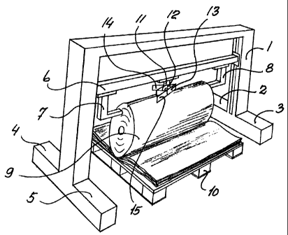
reference to the accompanying Drawings. Fig. 1 is a schematic, perspective
view
of one embodiment of an apparatus according to the present invention. Fig. 2
is a
view similar to that of Fig. 1 of another embodiment of an apparatus according
to
the present invention. Fig. 3 is a schematic view of a shuttle carriage for an
apparatus according to the present invention. Fig. 4 is a schematic view of
one
embodiment of a part of an apparatus according to the present invention.

The embodiment of an apparatus according to the present invention
schematically
illustrated in Fig. 1 has a frame I in the form of an inverted U with feet 2,
3, 4 and
5. Between the vertical shanks in the frame 1, a beam or boom 6 extends which
is
displaceable up and down in the frame 1. The beam or boom 6 carries side
supports 7 and 8 which are displaceable in the longitudinal direction of the
boom
or beam 6 for adapting to each end of a paper reel 9 which is placed in the
frame 1
and may rest on a per se conventional pallet 10. After placing of the side
supports
7 and 8 against the ends of the paper reel 9, it is appropriate to lock the
side
supports 7 and 8 in the desired position.

A shuttle-like carriage 11 is displaceable reciprocally on the boom or beam 6
between the side supports 7 and 8. The carriage 11 supports a roller knife 12
and a
plough 13 with two flaps 14 and 15. The plough 13 is double-directed and the
flaps 14 and 15 are adjustable for adaptation to the direction of movement of
the
plough 13 and the carriage 11.

In Drawing Figure 1, the parts are shown with the roller knife 12 during
cutting
work on movement from left to right on the reel 9. The layers or sheets cut
through during the preceding stroke have already fallen down onto the pallet
10.
The boom or beam 6 is fed progressively down towards the centre of the reel 9.
This downward movement ceases when the sleeve in the reel 9 is reached,
whereafter the pallet 10 with the severed sheets is conveyed off for recycling
to
the process. The sleeve is taken care of for possible re-use. The beam or boom
6 is
returned to its starting position, whereafter a new reel may be placed in the
frame


CA 02370730 2001-11-22

WO 00/62981 3 PCT/SEOO/00711
1. The beam or boom 6 is displaceable by means of screws or the like disposed
in
the frame legs.

In the embodiment of the present invention illustrated in Fig. 2, the frame 1
is
disposed on a leg 16 on the one side of the reel 9 and a leg 17 on the other
side of
the reel 9. In the legs 16 and 17, there are provided pins 18 for engagement
in the
sleeve of the reel 9 and lifting it up towards the shuttle carriage 11 with
the roller
knife 12 and the plough 13. In this embodiment, the severed sheets are
deposited
below the reel 9 and may be transported off in any suitable manner. Possibly,
a
conveyor may be provided for possible continuous removal of the sheets.

Drawing Figure 3 shows the carriage 11 in greater detail with the knife 12,
the
plough 13 and the flaps 14 and 15. It has proved to be suitable that the
roller knife
12 rotates when cutting such web-shaped material as fine paper and paperboard,
while the roller knife 12 may suitably be stationary when cutting such
material
qualities as, for example, tissue. The carriage I 1 is suitably connected to a
linear
prime mover, for example a pneumatic cylinder, a so-called shuttle cylinder,
for
reciprocal displacement between the ends of the reel 9. Suitably, the roller
knife
12 is freely running, but it may be both stationary and driven, depending upon
the
different material qualities. Fig. 3 illustrates more closely that the flaps
14 and 15
are secured on the plough 13 with the aid of hinges 19 centrally positioned on
the
plough 13 and permitting pivoting of the flaps 14 and 15 from the position
illustrated in Fig. 3 to the position illustrated in Figs. 1 and 2.

The roller knife 12 is mounted on a hub or shaft 20 at the end of a swing or
end
walls forming the shuttle carriage 11. The swing may be pivotal in the
direction of
the arrows thereon in Fig. 3 for angular positioning of the roller knife 12
and the
plough 13 in relation to the longitudinal axis of the reel 9. The roller knife
12
may, as was mentioned above, be freely rotated, driven or locked, depending
upon
the material variety on the reel 9. The shuttle carriage 11 may be mounted on
a
shuttle piston in a shuttle cylinder. Such an arrangement is exemplified in
Fig. 4
which will be described in greater detail below. The plough 13 may be
suspended
in bolts which extend from a plate which is connected to the shuttle carriage
11


CA 02370730 2001-11-22

WO 00/62981 4 PCTlSE00/00711
with the aid of a carrier or stub shaft. With the aid of the bolts, it is
possible to
adjust the plough in relation to the roller knife 12. The flaps 14 and 15 may
be
switchable with the aid of pistons which are suitably of the pneumatic type.

The arrangement exemplified in Fig. 4 displays a shuttle cylinder 27 with
three
pistons 28, 29 and 30. The piston 29 supports the shuttle 11 with the roller
knife
12, while the side supports 7 and 8 are mounted on the pistons 28 and 30,
respectively, the side supports 7 and 8 being urged against each end of the
reel 9.
The pistons 28, 29 and 30 divide the shuttle cylinder 27 into four chambers
31, 32,
33 and 34. When the chambers 31 and 34 are pressurised, the side supports 7
and
8 are urged against the ends of the reel 9. A somewhat lower pressure in the
chamber 32 will displace the piston 29 with the shuttle 11 and the roller
knife 12
from the piston 28 towards the piston 30. When the roller knife 12 has reached
or
passed the end of the paper reel 9, the pressurisation is switched from the
chamber
32 to the chamber 33 and the flaps 14 and 15 are switched for displacement of
the
roller knife 12 towards the piston 28, and thereby the other end of the reel
9. As
previously, the cylinder 27 is progressively displaced towards the reel 9 in
suitable cutting depths, or the reel 9 is displaced upwards towards the
cylinder 27.

When cutting such a material variety as tissue, it has proved to be suitable
to
maintain the roller knife 12 stationary and employ air jets as the plough
instead of
the mechanical plough 12 with the flaps 14 and 15 described in the foregoing.
Many modifications are naturally possible without departing from the scope of
the
inventive concept as defined in the appended Claims.

Representative Drawing
A single figure which represents the drawing illustrating the invention.
Administrative Status

For a clearer understanding of the status of the application/patent presented on this page, the site Disclaimer , as well as the definitions for Patent , Administrative Status , Maintenance Fee  and Payment History  should be consulted.

Administrative Status

Title Date
Forecasted Issue Date 2007-09-11
(86) PCT Filing Date 2000-04-14
(87) PCT Publication Date 2000-10-26
(85) National Entry 2001-11-22
Examination Requested 2005-04-04
(45) Issued 2007-09-11
Expired 2020-04-14

Abandonment History

There is no abandonment history.

Payment History

Fee Type Anniversary Year Due Date Amount Paid Paid Date
Maintenance Fee - Application - New Act 2 2002-04-15 $100.00 2001-10-18
Reinstatement of rights $200.00 2001-11-22
Application Fee $300.00 2001-11-22
Registration of a document - section 124 $100.00 2002-05-06
Maintenance Fee - Application - New Act 3 2003-04-14 $100.00 2003-04-09
Maintenance Fee - Application - New Act 4 2004-04-14 $100.00 2004-03-05
Request for Examination $800.00 2005-04-04
Maintenance Fee - Application - New Act 5 2005-04-14 $200.00 2005-04-04
Maintenance Fee - Application - New Act 6 2006-04-14 $200.00 2006-03-14
Maintenance Fee - Application - New Act 7 2007-04-16 $200.00 2007-04-04
Final Fee $300.00 2007-06-20
Maintenance Fee - Patent - New Act 8 2008-04-14 $200.00 2008-03-31
Maintenance Fee - Patent - New Act 9 2009-04-14 $200.00 2009-04-09
Maintenance Fee - Patent - New Act 10 2010-04-14 $250.00 2010-03-29
Maintenance Fee - Patent - New Act 11 2011-04-14 $250.00 2011-04-04
Maintenance Fee - Patent - New Act 12 2012-04-16 $250.00 2012-04-10
Maintenance Fee - Patent - New Act 13 2013-04-15 $250.00 2013-04-09
Maintenance Fee - Patent - New Act 14 2014-04-14 $250.00 2014-03-25
Maintenance Fee - Patent - New Act 15 2015-04-14 $450.00 2015-02-27
Maintenance Fee - Patent - New Act 16 2016-04-14 $450.00 2016-04-04
Maintenance Fee - Patent - New Act 17 2017-04-18 $450.00 2017-03-21
Maintenance Fee - Patent - New Act 18 2018-04-16 $450.00 2018-04-12
Maintenance Fee - Patent - New Act 19 2019-04-15 $450.00 2019-04-02
Owners on Record

Note: Records showing the ownership history in alphabetical order.

Current Owners on Record
CORE LINK AB
Past Owners on Record
ESPING, THOMAS
GORANSSON, JAN
JOHANSSON, KJELL
KARLSSON, JAN
LJUNGEK, GORAN
NILSSON, OVE
Past Owners that do not appear in the "Owners on Record" listing will appear in other documentation within the application.
Documents

To view selected files, please enter reCAPTCHA code :


To view images, click a link in the Document Description column. To download the documents, select one or more checkboxes in the first column and then click the "Download Selected in PDF format (Zip Archive)" or the "Download Selected as Single PDF" button.

List of published and non-published patent-specific documents on the CPD .

If you have any difficulty accessing content, you can call the Client Service Centre at 1-866-997-1936 or send them an e-mail at CIPO Client Service Centre.


Document
Description 
Date
(yyyy-mm-dd) 
Number of pages   Size of Image (KB) 
Representative Drawing 2007-08-14 1 22
Cover Page 2007-08-14 1 51
Representative Drawing 2002-04-04 1 18
Abstract 2001-11-22 1 61
Claims 2001-11-22 2 60
Drawings 2001-11-22 4 66
Description 2001-11-22 4 172
Cover Page 2002-04-05 1 46
Description 2005-06-13 5 205
Claims 2005-06-13 2 84
PCT 2001-10-18 10 382
Correspondence 2002-04-03 1 23
Correspondence 2001-11-22 1 51
Assignment 2002-05-06 3 97
Correspondence 2002-07-05 1 13
Assignment 2001-11-22 4 151
Fees 2003-04-09 1 32
Prosecution-Amendment 2005-06-13 6 204
Fees 2005-04-04 1 29
Fees 2001-11-22 1 54
Fees 2004-03-05 1 37
Prosecution-Amendment 2005-04-04 1 28
Fees 2006-03-14 1 36
Correspondence 2007-06-20 1 27