Note: Descriptions are shown in the official language in which they were submitted.
CA 02370809 2001-10-01
WO 00/60724 PCT/CA99/00290
HIGH PERFORMANCE BRUSHLESS MOTOR AND DRIVE FOR AN ELECTRICAL VEHICLE
MOTORIZATION
BACKGROUND OF THE INVENTION
The present invention relates to a lo , cost electric system composed of a new
DC
brushless permanent magnet motor and its electronic drive which provides high
efficiency operation and low torque ripple for the motorization of electric
vehicles like,
bicycles, rolling chairs, scooters, tricycles, golf cars, trolleys and small
utility vehicles.
The motor and its electronic system are supplied by one or several batteries.
The vehicle
wheel drive can be direct to maximize efficiency or equipped with a speed
reducer to
minimize the motor size. The proposed solution uses a permanent magnet three-
phase
motor which can reach four times the nominal torque. This motor structure
includes an
outer rotor which can be fitted into a vehicle wheel. It can be used as motor
or generator
with energy recuperation in the battery during braking periods or to create
electricity to
recharge battery, or power other devices by changing the motor. This motor
structure is
supplied by a PWM (Pulse Width Modulation) current controlled inverter. The
operator
can impose the machine torque level in motor or generator operation by setting
a current
reference. The shape of the alternative phase current waveform is rectangular
with a
width of 120 electrical degrees. This kind of motor supply is the simplest to
realize and it
reduces the cost of the control system and the number of sensors.
The brushless motor includes a cylindrical outer rotor wherein permanent
magnets are
mounted on the surface and an internal stator with coils of insulated wire
wound around
the teeth. There are twenty two magnet poles on the rotor alternatively
magnetized north
and south and twenty-four slots on the stator. This combination of slots and
poles for a
three-phase motor structure allows the realization of a special concentrated
winding
around the teeth with only one coil per slot. In this case, there are only
twelve coils to
realize. The winding coefficient and the copper filling factor are higher than
in the other
known solutions described by Konecny U.S. Pat. No. 4,774,428, Huang and al.
U.S. Pat.
No. 5,675,196 and Katsuma and al. U.S. Pat. No. 4,719,378 which are using
winding
with two coils per slot.
CA 02370809 2007-07-17
This kind of winding with one coil per slot simplifies the assembling of the
rotor
position sensors (i.e. hall detectors) near the air gap. The hall detector are
tixed on the
side of several teeth which have no winding and they are using the leakage
flux of the
permanent magnets to detect the rotor position.
The proposed structure maximizes the energy efficiency and the motor starting
torque
per unit volume of winding. The advantages of a concentrated winding around
the teeth
in comparison with a classical distributed winding ai-e descT-ibed in Konecny
U.S. Pat.
No. 4,774,428 and Permanent magnet Brushless DC motor with soft metal powder
for
automotive application - J. Cros, P. Viarouge IEEE Industry applications
Society - St-
Louis , October 1998. [1]. The volume of copper is reduced and subsequently
the Joule
losses are minimized.
The amount of vibrations and the cogging toi-que ripple ai-e reduced
drastically like in
the other structure combinations described by Konecny U.S. Pat. No. 4,774,428,
Huang
and al. U.S. Pat. No. 5,675,196 and Katsuma and al. U.S. Pat. No. 4,719,378.
The least
common multiple (LCM) of the motor's poles and slots describes how many peaks
of
cogging torque will be present over a single revolution of the motor. In this
case, thei-e
are 264 torque pulses per revolution and consequently, the cogging torque
amplitude is
very low (less than 3% of the rated torque).
The proposed motor structure also minimizes the net radial force like another
structLn-e
described by Huang and al. U.S. Pat. No. 5,675,196.
Reference is made to British Patent GB 2 289 991 which discloses a winding
sequence
for a motor having twelve slots and ten poles. It is described in that Patent
the use of a
specific rotor structure and a specific winding sequence wherein one winding
per slot is
provided to obtain independent magnetic flux flow for each phase.
Japanese Patent A-400 4703 relates to an electric bicycle most specifically to
a system
capable of detecting the direction of rotation of the rotor as well as its
speed by the use
of an optical sensor whereby to control the amplitude of the current in the
motor.
The electronic supply includes a power electronics supply and a cLu-rent
control
electronics circuit. Both systems can be inserted inside the motor housing, in
the center
of the statoi- yoke. The power electronics system is composed of an inverter
with six
Mosfets or multiple Mosfets which operate like six Mosfets. The structui-e
diodes of
the mosfets are used to ensure the current i-eversibility. At each sequence of
conduction
2
CA 02370809 2007-07-17
defined by the rotor position detector, two transistors are switched on to
supply two
motor phases. In the classical mode of operation, a modulation signal is
applied on the
gate of these two transistors. This method sinzplifies the control realization
and only
one current sensor can be inserted in the DC bus for the current measurement.
Another solution consists in applying the modulation sibmal on one transistor
only at
each sequence of operation: this method is the single switch modulation
technique. The
other transistor is switched "on" during all the duration of this sequence of
conduction.
This mode of operation is described in E.M.I. tests on a brushless actuator:
Coniparison
of M. Lajoie-Mazenc, J.P. Berry - European Power Electronics - Brighton
(U.K.),
September 1993 [Z], in the case of motoring operation only, compared to the
classical
mode of operation where the modulation signal is applied on the gate of the
two
transistors. It is shown that the single switch modulation provides lower
electromagnetic interferences (EMI) and reduces the commutation losses, the
conduction losses in low voltage applications, the current ripple and the size
of the
input filtering capacitor. The proposed electronic system is using the single
switch
modulation and it can be used for motor as well as generator operation.
Consequently,
the current regulation is realized without any external current sensor.
SUMMARY OF THE INVENTION
It is a feature of the present invention provide a high performance brushless
DC
permanent magnet motor and a pulse width, modulation electronic inverter for
the
motorization or electric vehicles supplied with electrical batteries. The
motor structure
includes an outer rotor which can be fitted to a vehicle wheel. It can be used
as a motor
or as a generator with recuperation of kinetic energy in the batteries during
braking
periods.
Another feature of the invention is to provide a special design and the design
of its
three-phase winding maximize the energy efficiency and the motor starting
torque per
unit volume of winding. A concentrated winding is wound around the teeth witli
only
one coil per slot. This solution simplifies the winding realization and
maximizes the
winding coefficient and the copper filling factor.
3
CA 02370809 2001-10-01
WO 00/60724 PCT/CA99/00290
Another feature of the invention is that the assembling of the rotor position
sensor (i.e.
hall detectors) near the air gap is simplified by the winding configuration.
The hall
detector are fixed on the side of several teeth which have no winding and they
are using
the leakage flux of the permanent magnets to detect the rotor position. The
amount of
vibrations, the cogging torque ripple and the radial force are greatly
reduced.
Another feature of the invention is to provide specific inverter control
system which
reduces the commutation losses, the diode conduction losses in low voltage
applications,
the current ripple, the size of the input filtering capacitor and
electromagnetic
interference. A specific single switch modulation technique is used: The
modulation
signal is applied only on one transistor at each sequence of operation defined
by the rotor
position detector. The other transistor is switched on during all the duration
of this
sequence of conduction. This single switch modulation method maximizes the
efficiency
of the electronic supply and the current regulation is realized without any
external current
sensor.
According to the above features, from a broad aspect, the present invention
provides a
brushless DC motor for electrical vehicle motorization. The motor comprises a
cylindrical rotor with 22 poles constructed with segments of permanent magnet
material
alternatively magnetized north and south. A stator core of ferromagnetic
material is
spaced inwardly of the rotor and defines a magnetic clearance gap
therebetween. The
stator core has twenty four slots and define teeth between the slots. A three-
phase
winding with coils of insulated wire is wound around the teeth. There is
provided one
coil per slot with predetermined connection patterns A', C, C, B', B', A, A,
C', C', B, B,
and A' resulting in reduced torque ripple without any slot or magnet skewing.
According to a still further broad aspect of the present invention there is
provided a
brushless DC motor as above described but wherein there is further provided
two coils
per slot having predetermined connection patterns C', C, C', C, B, B', B, B',
A', A, A', A,
C,C',C,C',B',B,B',B,A,A',A,A'.
4
CA 02370809 2001-10-01
WO 00/60724 PCT/CA99/00290
According to a still further broad aspect of the present invention there is
provided a
brushless DC motor electronic pulse with modulation driver and control system.
It
includes a power electronic three phase inverter having six power of mosfets.
A current
control system is coupled to the inverter for generating a 120 electrical
degrees
rectangular phase current pulses. An electronic control system is provided for
both motor
and a generator operation mode of the motor and uses a single switch
modulation
technique.
According to a still further broad aspect of the present invention there is
provided a
brushless DC motor for breaking a wheel of devices on which people are
displaced by
self-motorization or electric motor motorization. The motor comprises a
cylindrical rotor
with twenty two poles constructed with segments of permanent magnet material
alternatively magnetized north and south, a stator core of ferromagnetic
material spaced
inwardly of said rotor and defining a magnetic clearance gap, therebetween
said stator
core having twenty-four slots and defining teeth between said slots, a three
phase winding
with coils of insulated wire being wound around the teeth. The rotor is
connected to a
hub of the wheel. Control circuit means is provided to control the torque of
the motor
and therefore its arresting force.
BRIEF DESCRIPTION OF THE DRAWING
A preferred embodiment of the present invention will now be described with
reference to
the accompanying drawings in which:
Fig. 1 is a schematic diagram of a brushless DC motor structure including a
motor, a
power electronics system and a current control system;
Fig.2 is a diagrammatic view of the twenty-two pole rotor and the twenty-four
slot stator
arrangement in accordance with principles of the present invention;
Fig 3 is a first coil winding diagram arrangement with one coil per slot;
CA 02370809 2007-07-17
Fig 4 is a second coil winding arrangement with two coils per slot; Fig 5
indicates the position of the three Hall sensors in the motor which are used
to
detect the rotor position;
Fig 6 is a simplified diagram of the electronic system (power electronics
system
(inverter) and control system);
Fig 7 shows the conduction sequence order of the power mosfets;
Fig 8 shows the simplified waveforms of the phase current in phase with the
back
electromotive force;
Fig 9 shows the diagram of the mosfet control signals during one period of the
motor
operation mode;
Fig 10 indicates the current flow in the case of the sequence (TI - T2) in
motor
operation mode;
Fig 1 1 is a diagram of the mosfet conti-ol signals during one period of the
generator
operation mode;
Fig 12 indicates the curi-ent flow in the case of the sequence (TI - T2) in
generator
operation mode;
Figure 13 shows a schematic view of the current control;
Figure 14 is a schematic diagram of the transformation of the signals of the
rotor
position sensors and the generation of the mosfet gate control signals in
motoi-
operation mode;
Figure 15 is a schematic diagrani of the electronic system for the generation,
the
mosfet gate control signals, and the measurement of the phase current in the
motoi-
and generator operation mode with the single switch modulation technique, and
Figure 16 is a simplified fragmented side view showing the motor of the
present
invention coupled to a wheel of a bicycle through its rotor.
DETAILED DESCRIPTION OF THE INVENTION
In electrical vehicle applications, it is necessary to produce high starting
torque and to
ensure variable speed in both motor and generator modes of operation. The use
of a
brushless DC motor is particularly well adapted to this kind of applications.
To
reduce the cost of the electronic system and the number of sensors, it is
better to
supply the motor winding phases with a rectangular waveform current. The motor
torque is
6
CA 02370809 2007-07-17
controlled by a simple ciurrent regulation and the phase voltage is chopped
with a pulse
width modulation technique (PWM). The schematic diagram of this kind of
brushless DC
motor is presented on Fig. 1. It includes a permanent magnet motor 10, a power
electronic
supply 11, a rotor position detector 12, a cui-rent measurement systeni 13 and
a current
regulation systeni which is comprised of a current control circuit 14 fed by
the current
measuring circuit 13 and a torque reference or current reference circuit 16.
The current
control circuit 14 is connected to the powei- electric supply circuit 1 1 to
control the torque
of the motor 10. The system can be used for motor oi- generator operation with
enei-gy
recuperation on the battery 15 during braking periods.
As shown in Fig. 2, the proposed solution in the present invention is to use a
motor 10
structure having a twenty-two poles and twenty-four slots 18 witli a
cylindrical outer rotor
19. Permanent magnets 20 are mounted on the rotor inner surface 21 and
altenativelv
magnetized north and sotrth. The high number of poles reduces the iron volume
and
provides acceptable iron losses when the speed is less than 1,000 rpm. A
stator core (8) of
ferromagnetic material is spaced inwardly of the rotor (19) and magnets (20)
and def nes a
magnetic clearance gap (9) therebetween.
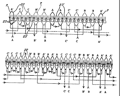
As shown in Fig's 3 and 4, a concentrated winding 22 is wound around the teeth
23. The
advantages of a concentrated winding around the teeth in comparison with a
classical
distributed winding ai-e desci-ibed in Konecny U.S. Pat. No. 4,774,428 and the
article
reference E.M.1 tests on a brushless actuator: Comparison of different
operation modes-J.
Cros, S. Astier, J.M. Vinassa, M. Lajoie-Mazenc, J.P. Berry- European Power
Electronics
- Brighton (UK), September 1993. [I]. The volume of copper is reduced and
subsequently
the Joule losses are minimized. The energy efficiency and the motor starting
torque per
unit volume of winding are maximized.
A first winding configuration with only one coil (7) per slot, as shown in
Fig. 3, maximizes
the winding coefficient (0.958) and the slot Elling factor and simplifies the
winding
realization. An alternative winding configuratioii with two coils per slots is
presented on
Fig 4 and it can be used for the proposed motor structure (winding coefficient
: 0.949).
Referring now to Fig. 5, the assembling of the rotor position sensor, i.e.
Hall detectors 24,
near the air gap 25, is simplified by the winding configuration of Fig. 3,
using oue coil pei-
slot . The Hall detectors 24 are fixed on the side of several teetli 23 which
have no
7
CA 02370809 2007-07-17
winding, such as teeth 23' in Fig. 3, and they are using the leakage flux of
the pernianent
magnets to detect the rotor position. Hall sensoi-s or detectors 24 are placed
to position the
phase current and the phase electromagnetic force (back emf) wavefornis like
in Fig's 7 &
8. The maximuni value of the torque to curi-ent ratio is then obtained with
this
configuration.
The cogging torque ripple are greatly reduced without any slot skewing, as in
the other
structure combinations described by Konecny U.S. Pat. No. 4,774,428, Huang and
al. U.S.
Pat. No. 5,675,196 and Katsuma and al. U.S. Pat. No. 4,7 19,378. The least
common
multiple (LCM) of the motor's poles and slots describes how many peaks of
cogging
torque will be present over a single revolution of the motor. In this case,
there ar-e 264
torque pulses per revolution and consequently, the cogging torque amplitude is
very low
(less than 3% of the rated torque). The pi-oposed motor structure also
minimizes the net
radial force like anothei- structure described by Huang and al. U.S. Pat. No.
5,675,196.
Referring now to Fig. 6 there is shown the electronic supply which includes a
power
electronics system and a low power conti-ol electronics system. Both systems
can he
inserted in the cavity 26 inside the motor housing, in the center of the
stator yoke 27. The
power electronics system is a six switches, PWM (pulse width modulation)
inverter 28.
Six type N Mosfets 28 (TI, T2, T3, Tyl, Ty2, T'3) are used and the structure
diodes of the
mosfets 29 are used to ensure the current reversibility. The electronic system
also includes
a push-pull driver 30 for each mosfet, tht-ee boostrap supplies 31 feed the
driver stages of
the three transistors T71, Ty2, T73 of the upper side of the inverter 28 and
three level-
shift control signals are applied to the driver stages of transistor T7 1,
T'2, T'3.
A current regulation circuit 32 generates a PWM signal at each transistor
control signal.
The voltages of the power mosfets 29' Tl, T2, T3 on the lower side 28' of the
inverter 28
are used to measure the motor currents. The rotor position sensors 24 define
the
conduction sequence oi-der and are also used to select the voltage of the
power mosfet 29
in conduction to be sensed by means of a multiplexer 33 with 3 inputs 33' and
1 output
33". The multiplexer 33 is used to generate a signal equivalent to the niotor
current,
8
CA 02370809 2001-10-01
WO 00/60724 PCT/CA99/00290
which can be used in the current regulation loop. The operator can select the
operation
mode of the system (motor or generator operation mode) and the current
reference level
to impose the torque of the machine.
Fig 7 presents the chronogram 37 of the conduction sequences of the power
mosfets 29.
At each time, there are only two Mosfets switched on. There are six sequences
of
operation in an electric period . During each sequence two phases of the
machine are
supplied. There are six current commutations when the rotor rotates with an
angle of
32.7 degrees. The commutation process is controlled by the rotor position
detectors 24
(i.e. Hall sensors).
Fig 8 shows the rectangular waveform 38 of the phase current which is in phase
with the
waveform 39 of the back electromotive force (back emf) of the same phase.
Referring now to Fig's 9 to 12., there is shown a single switch modulation
technique used
for both motor and generator operation. The modulation signal is only applied
on the gate
of the transistors of the inverter upper side (T' 1, T'2, T'3) in the case of
motor operation
mode ( see Fig 9 & 10). The transistors T1, T2, T3 remain switched "on" during
all the
duration of the conduction sequence. In comparison to the classical modulation
technique
where the modulation signal is applied to switches of both lower and upper
sides. This
specific single switch modulation technique provides lower commutation losses
and
lower conduction losses in the case of low voltage applications (the voltage
drop of a
power mosfet is lower than the voltage drop of a diode) see the E.M.I. tests
article
referred herein. The efficiency of the inverter 28 is higher. This single
switch modulation
technique simplifies the measurement of the phase currents and it eliminates
the need of
an external current sensor. The voltages of the Mosfets (T1, T2, T3) of the
inverter lower
side 28' can be used to measure the motor phase currents during all the
sequences. In the
case of the sequence T'1-T2, the voltage of transistor T2 is used to measure
the motor
phase current.
Fig 9 shows the control signals which are applied to the transistor gates in
the case of the
single switch modulation technique.
9
CA 02370809 2001-10-01
WO 00/60724 PCT/CA99/00290
Fig 10 shows the current flow during one sequence in the motor operation mode.
When
transistors T' 1 and T2 are switched "on" (Fig 10a), the battery supplies two
phases 40
and 41 of the motor. When the transistor T' 1 is switched "off', the structure
diode of
mosfet T1 is switched "on" and a free wheeling operation is occurring
(FiglOb). The
current ripple is reduced by half in comparison with the classical two-switch
modulation
technique. There is no current inversion in the DC bus and so the size of the
filtering
capacitor (not shown but well known in the art) can be reduced (lower RMS
current on
the DC bus). Consequently, the electromagnetic interferences are also lower
than in the
case of the classical modulation mode see the E.M.I. article referred herein.
Fig's 11 & 12 present the case of the generator operation mode. The upper side
inverter
transistors 29 T' l, T'2, T'3 are all switched "off' during the generator
operation mode.
Only the structure diodes of these transistors are used in this mode. A
modulation signal
is applied on the gate 42 of transistors Tl, T2, T3 (see Fig. 6) in the lower
side 28' of the
inverter 28. There are some intervals where permanent conduction is occuring.
They are
used to measure the mosfet voltage for the current control (see Fig 12). Fig
12 shows the
current flow during one sequence of operation. The machine or motor current
increases
when the transistors 30 Tl, T2 are switched "on" (Fig 12b). When transistor T1
is
switched "off', the structure diode of transistor T' 1 is switched "on" and
the machine
supplies the battery 43 (Fig 12a).
Fig's 13 and 14 show block diagram views of a classical current regulation
with a PI
regulator 44 which can be applied in the case of the single switch modulation
mode. The
proposed electronic system for both motor and generator operation modes with
the single
switch modulation technique is presented on fig 15. This system includes two
signal
multiplexers and several AND/OR gates used to control the signals applied to
the
transistor driver stages and the signals of measurements of the machine
current. The
system is also realizable by an integrated circuit or a programmable circuit
obvious to a
person skilled in the art.
It is within the ambit of the present invention to cover any obvious
modifications
provided such modification fell within the scope of the appended claims.
CA 02370809 2001-10-01
WO 00/60724 PCT/CA99/00290
Referring now to Figure 16 there is shown a brushless DC motor 50, constructed
as above
described, and wherein the rotor 51 is connected to a hub 52 of a wheel 53
herein a
bicycle wheel. Alternatively, to reduce production cost, the motor cover
housing may
have connections to which the spokes of the wheel are connected to. A battery,
not
shown, is conveniently secured to the bicycle and power is fed to the control
circuitry
provided or mounted within the cavity inside the stator. A cable 54 is secured
to a
control device which is operated by the user of the bicycle to control the
speed of the
motor. This control device could be in the form of a rotating handle and grip,
a hand
lever device or any other convenient means. When the motor is used as a
motorizing
machine it drives the wheel 53. The motor can also be utilized as a break when
placed in
its generating mode. As previously mentioned, this motor can be secured to all
sorts of
electrical vehicles such as wheel chairs, scooters, tricycles, golf trolleys,
small utility
vehicles, etc.
11