Note: Descriptions are shown in the official language in which they were submitted.
CA 02371038 2001-10-22
WO 00/66247 PCT/US00/11562
-1-
IMPROVED VACiJUM CLEANER
1. Field of the Invention
This invention relates to a vacuum cleaner of the type for household use.
2. Description of the Prior Art
Water bath vacuum cleaners typically include a main housing with a removably
attached water bath pan. An intake opening in the water bath pan matingly
engages an
inlet in the main housing of the vacuum cleaner to allow dust and dirt
entrained air to
be ingested by a vacuum force through the inlet into the area defined by the
water bath
pan. The primary advantage of the water bath filter is that vacuum efficiency
is not
compromised as more dirt and dust is accumulated in the water bath, and no
further
filtering is viewed as necessary. The dust and dirt are trapped in the water
bath as the
incoming air is directed into the water bath pan and circulated within.
Traditional
filtering media allow the flow of air through the filtering media to be
impeded by the
accumulation of the dirt and dust that has collected thereon. However, just as
traditional filter media will allow very tiny microscopic particles to escape
capture, the
water bath and separator may also fail to capture all of the very small or
microscopic
particles that are light enough to remain suspended in the air as the air is
circulated in
the water bath pan.
High efficiency filters, or HEPA rated filters, are used on vacuum cleaners in
industrial and residential applications. These filters are made up of filter
media with
very tiny openings that are designed to capture the smallest microscopic
particles that
most traditional filter media or methods are incapable of capturing. The major
drawback to the use of these types of filters is that due to the small size of
the openings
in the filter media, they capture all of the dirt and debris that hits them
thereby
clogging up very quickly, and requiring cleaning or replacement very often.
For this
reason, some vacuum cleaning products try to combine the HEPA rated filter
with a
more conventional dry filter media. The conventional dry filter media will
capture the
CA 02371038 2001-10-22
WO 00/66247 PCT/US00/11562
-2-
larger particles of dirt and debris, and the HEPA rated filter will only
capture the
smaller particles that escape the conventional dry filter media. The overall
efficiency
of the vacuum cleaner (and the conventional dry filter media) is affected as
the air is
redirected and routed through the additional filter. Also, the full area of
the high
efficiency filter is not utilized because the air is typically directed
through a small
opening in the main housing of the vacuum cleaner, which concentrates the flow
of air
on the portion of the high efficiency filter that is directly in front of the
opening.
CA 02371038 2001-10-22
WO 00/66247 PCT/US00/11562
-3-
"Error! Bookmark not defined.
The present invention relates to a vacuum cleaner assembly comprising a main
housina having an inlet and an outlet. A motor is disposed within the main
housing
between the inlet and the outlet for providing motive force to a cooling fan,
a blower,
and a separator. The cooling fan is mounted within the main housing above the
motor
to circulate cooling air around the motor. A baffle is mounted within the main
housing
for directing the cooling air around the motor, and to filter the air that is
circulated
around the motor before that air is exhausted. The blower is mounted within
the main
housing below the motor for drawing air into the inlet and exhausting air
outwardly
through the outlet. The separator is mounted below the blower for circulating
the air
and water within a water bath and providing, in combination with the water
bath, a
primary filter for filtering the air prior to exhausting the air outwardly
through the
outlet. A second filter assembly including a high efficiency filter, known as
a HEPA
rated filter, for filtering microscopic dust and dirt particles that escape
the separator
and water bath and may be disposed after both the water bath and the separator
and
before the outlet to atmosphere for additional filtering of the air prior to
being
exhausted. The second filter assembly may also include a third filter
comprising a
carbon impregnated filter of a reticulated foam or similar material for
absorbing or
trapping odors drawn from the air, including smoke and fish odors. The second
filter
and the carbon impregnated filter are disposed in a recess which is integral
with the
main housing allowing for direct and efficient flow of the air through the
water bath,
separator, second filter, and carbon impregnated filter. In an alternative
embodiment,
the second filter can be a non-HEPA filter used in combination with the carbon
impregnated filter.
Accordingly, the present invention will utilize the separator and water bath
filter to capture the larger particles of dirt and debris prior to routing the
air through the
second, HEPA rated or non-HEPA rated filter to capture microscopic particles
that
escape the water bath, and finally through the carbon impregnated filter to
absorb or
trap odors. The recess for the high efficiency filter is located integrally to
the main
housing allowing the air to flow directly from the water bath canister through
the
CA 02371038 2001-10-22
WO 00/66247 PCT/US00/11562
-4-
second filter and the carbon impregnated filter with minimal redirection of
the air and
no noticeable impact on the primary filter. This will allow the air to flow
smoothly
through the series of filters. The second filter assembly will not be overly
clogged
because the separator and water bath will capture the majority of the larger
dust and
dirt particles before the air goes through the second filter assembly. The
recess is
designed to allow the majority of the surface area of the high efficiency
filter to be in
the direct line of airflow thereby the overall efficiency of the vacuum
cleaner is
maximized.
BRIEF DESCRIPTION OF THE DRAWINGS
Other advantages of the present invention will be readily appreciated as the
same becomes better understood by reference to the following detailed
description
when considered in connection with the accompanying drawings wherein:
Figure 1 is a perspective view of the vacuum cleaner assembly, partially
broken away and in cross section;
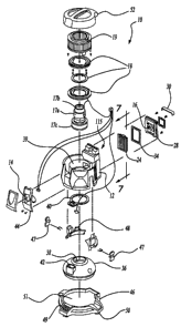
Figure 2 is an exploded perspective view of the vacuum cleaner assembly;
Figure 3 is an elevational view of the vacuum cleaner main housing shown
with the second filter seated in the recess defined by the housing;
Figure 4 is an exploded perspective view of the second filter assembly
including a five sectioned HEPA rated filter and a carbon impregnated
reticulated
foam filter;
Figure 5 is an exploded perspective view of the second filter assembly
including a nine sectioned HEPA rated filter and a carbon impregnated
reticulated
foam filter;
Figure 6 is an exploded perspective view of the second filter assembly
including a filter that is not HEPA rated and a carbon impregnated reticulated
foam
filter; and
Fiaure 7 is a cross-section along lines 7-7 of Figure 2.
CA 02371038 2001-10-22
WO 00/66247 PCT/US00/11562
-5-
DETAILED DESCRIPTION OF THE PREFERRED EMBODIMENT
Referring to the Figures, wherein like numerals indicate like or corresponding
parts throughout the several views a vacuum cleaner assembly is generally
shown at
10. The vacuum cleaner assembly 10 includes a main housing 12 having an inlet
14
and an outlet 16. A motor 17a is supported by support rings 18 within the main
housing 12 between the inlet 14 and the outlet 16 for providing motive force
to a
cooling fan 17b, a blower 17c, and a separator 22. The cooling fan 17b is
mounted
within the main housing 12 above the motor 17a to circulate cooling air around
the
motor 17a. A baffle 19 surrounds the motor 17a to direct the cooling air
around the
motor 17a and to filter the cooling air prior to being exhausted. The blower
17c is
mounted within the main housing 12 below the motor 17a for drawing air into
the inlet
14 and exhausting air outwardly through the outlet 16. The separator 22 is
mounted
below the blower 17c for circulating the air and a water bath 20 within a
water bath
pan 36 and providing, in combination with the water bath 20, a primary filter
for
filtering the air prior to exhausting the air outwardly through the outlet 16.
Vacuum
cleaners using a water bath 20 filter are known to those skilled in the art as
described
in United States Patent No. 5,096,475, which is hereby incorporated by
reference to
this specification.
A second filter assembly 24 is secured to the main housing 12 and preferably
includes a high efficiency filter 100 or 100a, known as a HEPA rated filter,
for filtering
microscopic dust and dirt particles that escape the separator 22 and water
bath 20 and
is disposed after both the water bath 20 and the separator 22 and before the
outlet 16
for additional filtering of the air prior to being exhausted. The differences
between
filter 100 and filter 100a are shown in Figures 4 and 5. The filter 100 has
compartments sectioned along five sets of ribs 102, and made preferably of
sheet
polypropylene. The filter 100a has compartments sectioned along nine sets of
ribs
103. The ribs maintain the integrity of the filter against air pressure and
other
environmental effects and are preferably made from hot metal glue, although
stamped
aluminum and plastic ribs are alternatives.
CA 02371038 2001-10-22
WO 00/66247 PCT/US00/11562
-6-
In another alternative embodiment, the second filter assembly 24 can include a
filter that is not HEPA rated 101, as shown in Figure 6 and combined in the
description
as discussed below and shown in Figure 6.
As a further alternative, a third filter 110 can be included as shown in
Figures
4, 5 and 6 which comprises a carbon impregnated reticulated foam filter 110
for
absorbing or trapping odors and is disposed in the air flow after the second
filter 100,
100a or 101 and before the outlet 16 to atmosphere. The second filter 100,
101, or
100a and the carbon impregnated filter 110 are secured together by glue or
some
equivalent means into a molded styrene frame 112 with a sealing gasket 114
associated
with one edge of the frame 112. This is shown in section in Figure 7 where the
filter
of Figure 2 is shown with the non-HEPA rated filter configuration of filter
101, but
which could just as readily be shown with the HEPA rated filter configurations
of 100
or 100a inserted for the filter 101. The surface area of the frame 112
adjacent the main
housing 12 is at least five times larger than the surface area of the main
housing 12
outlet. Preferably, the surface area of the frame 112 adjacent the main
housing is nine
times larger than the surface area of the main housing 12 outlet. The main
housing 12
defines a recess 26 and the second filter assembly 24 is seated in that recess
26 with
the sealing gasket 114 sealing against the main housing 12 at surface 115 to
force the
air to the outlet 16 through the second filter assembly 24.
Figure 2 shows an exploded view of the vacuum cleaner assembly 10. The
second filter assembly 24 is secured in position by a rear cover 28 which is
removably
attached to the main housing 12 via screws to cover the opening of the recess
26 and
secure the second filter assembly 24 in position. The rear cover 28 includes a
stowage
device 30 for stowing an electrical cord. A foam seal 34 is disposed between
the
assembly 24 and the rear cover 28 to cushion and sound deaden that area of the
vacuum as well as further prevent air from escaping anywhere other than via
the outlet
16. The second filter assembly 24 has smaller openings to capture particles
passing
through the separator 22 and water bath 20. In the preferred embodiment, the
second
filter assembly 24 includes a HEPA rated filter 100 or 100a for capturing tiny
microscopic dust and dirt particles.
CA 02371038 2001-10-22
WO 00/66247 PCT/US00/11562
-7-
Reuseable washable HEPA rated filter media, such as a pleated GORE-TEXtm
material, can also be used as the second filter 100 or 100a. Preferably, the
reuseable
washable filter media would be used as a HEPA rated filter, although if the
particulate
penetration size of the media selected were greater, the filter media would
not be a
HEPA rated filter, such as is the case with filter 101. Reuseable washable
filter media
would be advantageous in this device because it can be washed and reused along
with
or intermittently with the disposal of the water bath 20 from the water bath
pan 36 after
use.
The vacuum cleaner assembly 10 includes a water bath pan 36 for containing
the water bath 20. The water bath pan 36 presents a first opening 38 which is
disposed
directly below the main housing 12 which has a bottom opening 39 that
corresponds to
the first opening 38 in the water bath pan 36. A foam seal 40 forms a sealed
engagement between the water bath pan 36 and the bottom opening 39 of the main
housing 12. The water bath pan 36 also includes a second opening 42 which
corresponds to a tubular member extending from an inlet face plate 44. The
foam seal
40 forms a sealed engagement between the second opening 42 in the water bath
pan 36
and the inlet face plate 44. The inlet face plate 44 is mounted to the main
housing 12
at the inlet 14 and allows attachments to be connected in direct communication
with
the inlet 14.
The motor 17a is centrally supported by support rings 18 in the main housing
12 above the bottom opening 39. The separator 22 is attached to the motor 17a
below
the blower 17c and extends downwardly through the bottom opening 41 in the
main
housing 12 and the first opening 38 in the water bath pan 36. The separator 22
is
rotated by the motor 17a for circulating the air within the water bath pan 36
and for
drawing the dust and dirt entrained air, along with water from the water bath
20, within
the separator 22 for further capture of debris in the water bath 20 and to
direct, by
centrifugal force, the water and any remaining dirt or dust back outward into
the water
bath pan 36 for additional separation as it is drawn within the separator 22
again. As
the dust, dirt, and water are forced outward from the separator by centrifugal
force, the
CA 02371038 2001-10-22
WO 00/66247 PCT/US00/11562
-8-
filtered air is drawn upward out of the separator 22 outwardly through the
second filter
assembly 24.
A dolly 46 is positioned below the water bath pan 36. The water bath pan 36
attaches to the main housing 12 with at pair of latches 47 to secure the water
bath pan
36 to the main housing 12. The main housing 12 attaches to the dolly 46 and is
held
securely in place by a latch which is released upon activation of a release
button 49.
An interlock switch 48 is mounted to the main housing 12 and detects the
presence of
the water bath pan 36 when the dolly 46 is assembled to the main housing 12.
The
dolly 46 includes a seat 51 for the main housing and casters 50 are mounted to
the
dolly 46 to provide movable support for the vacuum cleaner assembly 10. The
vacuum cleaner assembly 10 also includes a top cover 52 with a handle attached
to the
top of the main housing 12 to close off the top and cover the motor 17a,
cooling fan
17b, support rings 18, and blower 19. The top cover 52, main housing 12, and
dolly
46 when assembled enclose all inner components of the vacuum cleaner assembly
10.
The invention has been described in an illustrative manner, and it is to be
understood that the terminology which has been used is intended to be in the
nature of
words of description rather than of limitation.
Modifications and variations of the present invention are possible in
light of the above teachings. It is, therefore, to be understood that within
the
scope of the appended claims, wherein reference numerals are merely for
convenience and are not to be in any way limiting, the invention may be
practiced otherwise than as specifically described.