Note: Descriptions are shown in the official language in which they were submitted.
CA 02371133 2001-11-15
WO 00/75476 PCT/EP00/04996
METHOD OF CREATING A WELLBORE
The present invention relates to a method of creating
a wellbore in an earth formation, the wellbore including
a first wellbore section and a second welibore section
penetrating a hydrocarbon fluid bearing zone of_the earth
formation.
In conventional methods of wellbore drilling a drill
string including a drill bit at its lower end is rotated
in the wellbore while drilling fluid is pumped through a
longitudinal passage in the drill string, which drilling
fluid returns to surface via the annular space between
the drill string and the wellbore wall. When drilling
through an earth layer not containing a fluid, the weight
and the pumping rate of the drilling fluid are selected
so that the pressure at the wellbore wall is kept between
a lower level at which the wellbore becomes unstable and
an upper level at which the wellbore wall is fractured.
When the wellbore is drilled through a hydrocarbon fluid
containing zone the drilling fluid pressure should
moreover be above the pressure at which hydrocarbon fluid
starts flowing into the wellbore, and below the pressure
at which undesired invasion of drilling fluid into the
formation occurs. These requirements impose certain
restrictions to the drilling process, and particularly to
the length of the wellbore intervals at which casing is
to be installed in the wellbore. For example, if the
drilling fluid pressure at the wellbore bottom is just
below the upper limit at which undesired drilling fluid
invasion into the formation occurs, the drilling fluid
pressure at the top of the open-hole wellbore interval
can be close to the lower limit at which undesired
hydrocarbon fluid influx occurs. The maximum allowable
Substitute sheet (Rule 26)
CA 02371133 2001-11-15
WO 00/75476 PCT/EP00/04996
- 2 -
length of the open-hole interval depends on the specific
weight of the drilling fluid, the hydrocarbon fluid
pressure in the formation, and the height of the drilling
fluid column.
Furthermore, it has been practised to drill through a
hydrocarbon fluid bearing zone at wellbore pressures
below the formation fluid pressure, a methodology
commonly referred to as under-balanced drilling. During
under-balanced drilling hydrocarbon fluid flows into the
wellbore, and consequently the drilling equipment at
surface has to be designed to handle such inflow.
Moreover, special measures must be taken to control the
fluid pressure in the wellbore during the drilling
process.
It is an object of the invention to provide a method
of drilling a wellbore through a hydrocarbon fluid
bearing zone of the earth formation, which method
alleviates the restrictions imposed to the drilling
process in conventional wellbore drilling and which
allows the wellbore pressure to be below the formation
fluid pressure while any hydrocarbon fluid inflow into
the wellbore can be adequately handled.
In accordance with the invention there is provided a
method of creating a wellbore in an earth formation, the
wellbore including a first wellbore section and a second
wellbore section penetrating a hydrocarbon fluid bearing
zone of the earth formation, the method comprising
- drilling the first wellbore section;
- arranging a remotely controlled drilling device at a
selected location in the first wellbore section, from
which selected location the second wellbore section is to
be drilled;
- arranging a hydrocarbon fluid production conduit in
the first wellbore section in sealing relationship with
the wellbore wall, the conduit being provided with fluid
Substitute sheet (Rule 26)
CA 02371133 2001-11-15
WO 00/75476 PCT/EP00/04996
- 3 -
flow control means and a fluid inlet in fluid
communication with said selected location;
- operating the drilling device to drill the second
wellbore section whereby during drilling of the drilling
device through the hydrocarbon fluid bearing zone, flow
of hydrocarbon fluid from the second welibore section
into the production conduit is controlled by the fluid
flow control means.
By drilling through the hydrocarbon fluid bearing
zone using the remotely controlled drilling device, and
discharging any hydrocarbon fluid flowing into the
wellbore through the production conduit, it is achieved
that the wellbore pressure no longer needs to be above
the formation fluid pressure. The wellbore pressure is
controlled by controlling the fluid flow control means.
Furthermore, no special measures are necessary for the
drilling equipment to handle hydrocarbon fluid production
during drilling.
In case the second wellbore is to be drilled through
one or more layers from which no hydrocarbon fluid flows
into the wellbore, it is preferred that the drilling
device comprises a pump system having an inlet arranged
to allow drill cuttings resulting from the drilling
action of the drilling device to flow into the inlet, and
an outlet arranged to discharge said drill cuttings into
the wellbore behind the drilling device.
Suitably said outlet is arranged a selected distance
behind the drilling device and at a location in the
wellbore section where a fluid is circulated through the
wellbore, which fluid entrains the drill cuttings and
transports the drill cuttings to surface.
The second wellbore section can be a continuation of
the first wellbore section, or can be a side-track (i.e.
a branch) of the first wellbore section.
Substitute sheet (Rule 26)
CA 02371133 2001-11-15
WO 00/75476 PCT/EPOO/04996
- 4 -
The invention will be explained hereinafter in more
detail and by way of example with reference to the
accompanying drawings in which
Fig. 1A schematically shows a lower part of an
embodiment of a drilling device used in the method of the
invention;
- Fig. lB schematically shows a continuation in upward
direction of the embodiment of Fig. 1;
Fig. 2 schematically shows the drilling device of
Figs. 1A and 1B before drilling of the second wellbore
section; and
Fig. 3 schematically shows the drilling device of
Figs. 1A and 1B during drilling the second wellbore
section.
Referring to Figs. 1A and 1B there is shown a
wellbore 1 in which a remotely controlled drilling
device 3 is arranged. The drilling device 3 has a
cylindrical housing 5 provided with an motor/pump
assembly 7 including an electric motor 9 having a
cylindrical stator 10 and a hollow rotor 12 coaxially
arranged within the stator. The rotor 12 is arranged to
drive a drill bit 13 located at the lower end of the
drilling device 3. A pump 14 of the assembly 7 is similar
in construction to a wellknown Moineau type motor and
consists of a rotor 16 formed by a cylindrical body of
elastomeric material 16a having a longitudinal, lobed
passage 16b, and a stator 20 formed by a helical member
extending through the passage 16b. The body of
elastomeric material 16a and the helical member 20 are
dimensioned such that fluid is pumped through the
passage 16b upon rotation of the body of elastomeric
material 16a relative to the helical member 20, whereby
the pumping direction depends on the direction of
relative rotation. The body of elastomeric material 16a
is fixedly connected to the inner surface of the rotor 12
Substitute sheet (Rule 26)
CA 02371133 2001-11-15
WO 00/75476 PCT/EP00/04996
- 5 -
of the electric motor so that during normal operation the
body of elastomeric material 16a is rotated by the
rotor 12. The direction of rotation of the electric
motor 9 is such that during operation of the motor fluid
is pumped through the passage 16b in the direction away
from the drill bit 13. The helical member 20 is at the
end thereof opposite the drill bit 13 connected-to a
bulkhead 22 via an electrically operated clutch 24, the
bulkhead 22 being fixedly arranged within the housing 5.
When in engaged mode, the clutch 24 prevents rotation of
the helical member 20 relative to the bulkhead 22, and,
when in disengaged mode allows rotation of the helical
member 20 relative to the bulkhead 22.
The drill bit 13 is provided with a passage 26
providing fluid communication between the bottom 28 of
the drill bit 13 and the passage 16b. The passage 16b is
at the side remote from the drill bit 13 in fluid
communication with an outlet conduit 34 passing through
an opening 36 provided in the bulkhead 22 and extending a
selected distance into the wellbore 1 away from the drill
bit 13. A device 38 for breaking drill cuttings by
mechanical or electromagnetic means into small particles
is arranged in the housing 5 between the pump 14 and the
opening 36 provided in the bulkhead 22.
The housing 5 is provided with a front stabiliser 40
arranged near the drill bit 13 and a rear stabiliser 42
arranged near the end of the housing 5 opposite the drill
bit 13. Both stabilisers 40, 42 are operable so as to be
concentrically or eccentrically positioned relative to
the housing 5 by electronic control means (not shown). A
set of four hydraulically operated, radially extendible
grippers 44 (only two of which are shown) is arranged at
a selected location between the stabilisers 40, 42. Each
gripper 44 is slideable a selected stroke in longitudinal
direction of the housing 5 along a guide bar 46 provided
Substitute sheet (Rule 26)
CA 02371133 2001-11-15
WO 00/75476 PCT/EP00/04996
- 6 -
at the housing S. The housing is provided with a
hydraulically operated thruster assembly 48 for thrusting
each gripper 44 along its respective guide bar 46. The
grippers 44 and the thruster assembly 48 are operated by
hydraulic power and controlled by an electronic control
system (not shown). The hydraulic power is supplied by a
piump unit (not shown) driven by a secondary electric
motor (not shown).
An electric conductor wire in the form of cable 50 is
connected to the end of the housing 5 opposite the drill
bit 13, by means of a releasable connector 51 which
includes a latching mechanism (not shown) for latching
the cable 50 into a recess 52 provided at the rear end of
the housing 5. An inductive coupler 54 connects the
cable 50 to the electric motor 9, the device 38, the
control means for the stabilisers 40, 42, the secondary
electric motor for driving the fluid pump, the electronic
control system for the grippers and the thruster
assembly, and the electrically operated clutch 24 and
mechanical coupling 58. The end of the cable near the
mechanical connector 51 is provided with a plurality of
formation evaluation sensors 56 electrically connected to
recording equipment (not shown) at surface via the
cable 50.
To retrieve the cable 50 from the drilling device 3
in case of a power failure via the cable 50, the drilling
device 3 is provided with an independent electric power
source (not shown) which radially retracts the
grippers 44 and releases the connector 51 in case of such
power failure.
An inertial navigation system (INS, not shown) is
included in the drilling device 3 for sampling data to
assist navigation of the drilling device 3 through the
wellbore 1.
Substitute sheet (Rule 26)
CA 02371133 2001-11-15
WO 00/75476 PCT/EPOO/04996
- 7 -
Normal operation of the drilling device 3 is
described hereinafter with further reference to Figs. 2
and 3.
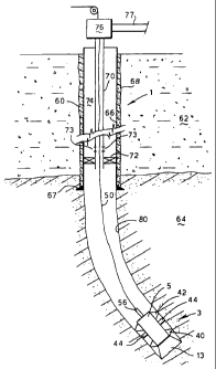
Referring to Fig. 2, a first section 60 of the
wellbore 1 is drilled through an upper earth formation
layer 62 until the wellbore 1 reaches a hydrocarbon fluid
reservoir layer 64 of the earth formation located below
the upper layer 62. A conventional drilling assembly is
used for this purpose, and the wellbore 1 is filled with
a suitable drilling fluid. A metal casing 66 with a
casing shoe 67 at its lower end is arranged in the first
wellbore section 60 and fixed to the wellbore wall by a
layer of cement 68. The drilling device 3 is releasably
connected to the lower end of a hydrocarbon production
tubing 70 by a suitable connecting device (not shown),
which tubing 70 is at its lower end part provided with an
inflatable packer 72 and with two circulation ports 73
located just above the packer 72, the circulation
ports 73 being operable between an open position and a
closed position by fluid pressure pulses external the
tubing 70. The tubing 70 is then lowered into the
casing 66 until the drilling device 3 is near the bottom
of the first wellbore section 60, whereafter the tubing
is fixed to the casing by inflating the packer 72 which
seals the annular space 74 formed between the tubing 70
and the casing 66. A wellhead 76 at surface provides
fluid communication between the tubing 70 and a
hydrocarbon fluid processing facility (not shown) via a
pipe 77. The wellhead 76 is provided with a valve (not
shown) for controlling flow of fluid from the tubing 70
to the processing facility. The annular space 74 above
the packer 72 is filled with brine.
The cable 50 is lowered through an opening (not
shown) in the wellhead 76 and through the tubing 70 until
the latching mechanism of the cable 50 latches into the
Substitute sheet (Rule 26)
CA 02371133 2001-11-15
WO 00/75476 PCT/EP00/04996
- 8 -
recess 52 of the drilling device 3. If necessary the
cable 50 is pumped through the tubing 70 until the
latching mechanism latches into the recess 52, in which
case the circulation ports 73 are first opened by a fluid
pressure pulse from the brine in the annular space.
Referring further to Fig. 3, a second wellbore
section 80 is drilled using the drilling device-3 in the
manner described hereinafter, the second wellbore section
being a continuation of the first wellbore section 60 and
extending into the reservoir layer 64. To start drilling
of the second wellbore section 80, electric power is
supplied via cable 50 to the secondary electric motor
thereby driving the pump unit which supplies hydraulic
power to the grippers 44 and the thruster assembly 48.
Control signals are supplied via the cable 50 to the
clutch 24 so as to disengage the clutch and to the
electronic control system so as to induce the grippers 44
to radially extend until the grippers 44 are firmly
pressed against the casing 66, and thereafter to induce
the thruster assembly 48 to thrust the grippers 44 along
their respective guide bars in rearward direction thereby
thrusting the drill bit 13 against the wellbore bottom.
Simultaneously electric power is supplied via the
cable 50 to the electric motor 9 thereby rotating the
drill bit 13. The helical member 20 rotates together with
the rotor 12 and with the body of elastomeric material
16a by virtue of the clutch 24 being disengaged, so that
the pump 14 is not operating.
As a result of the rotation of the drill bit 13
against the wellbore bottom the wellbore is deepened
until the grippers 44 reach the end of=1their stroke in
rearward direction. The electronic cont)rol system is then
operated to induce the grippers to radially retract, to
move the grippers 44 to the end of their stroke in
forward direction, and to induce the grippers 44 to
Substitute sheet (Rule 26)
CA 02371133 2001-11-15
WO 00/75476 PCT/EP00/04996
- 9 -
radially extend until becoming firmly pressed against the
wellbore wall. The thruster assembly 48 is then induced
to thrust the grippers 44 again in rearward direction
thereby deepening the wellbore 1 a further incremental
depth. This procedure is repeated as many times as
necessary to reach the desired depth of the wellbore 1.
If the wellbore trajectory needs to be changed the
electronic control means for controlling the
stabilisers 40, 42 is operated to induce the stabilisers
to assume a selected eccentric position relative to the
housing 5 so that the drill bit 13 becomes tilted in the
wellbore 1 and thereby starts drilling a curved wellbore
section. Once the desired orientation of the wellbore 1
is reached, the stabilisers are induced to assume a
concentric position relative to the housing 5 resulting
in further drilling of a straight section.
As drilling with the drilling device 3 proceeds, the
formation evaluation sensors 56 are operated to measure
selected earth formation characteristics and to transmit
signals representing the characteristics via the cable 50
to the recording equipment at surface.
During drilling of the second wellbore section 80
hydrocarbon fluid flows from the reservoir layer 64 into
the second wellbore section 80, and from there via the
tubing 70, the wellhead 76, and the pipe 77 to the
processing equipment. The drilling fluid initially
present in the wellbore 1 is thereby gradually replaced
by hydrocarbon fluid. The rate of flow is dependent on a
pressure difference between the reservoir layer 64 and
the interior of the second wellbore section 80, and is
controlled by controlling the valve at the wellhead 76.
As the hydrocarbon fluid flows through the second
wellbore section 80, the drill cuttings resulting from
the drilling process are entrained into the stream of
Substitute sheet (Rule 26)
CA 02371133 2001-11-15
WO 00/75476 PCT/EPOO/04996
- 10 -
hydrocarbon fluid and transported to the processing
facility.
In case the earth formation includes a plurality of
reservoir layers separated by rock layers (containing no
fluid), the drill cuttings are removed from the wellbore
during drilling of the drilling device through a rock
layer in the following manner. Suitable control-signals
are transmitted via the cable 50 to the clutch 24 so as
to engage the clutch 24 and to operate the device 38. As
a result of the clutch becoming engaged the helical
member 20 of the pump 14 becomes stationary while the
body of elastomeric material 16a rotates, so that the
pump 14 pumps fluid present in the wellbore (hydrocarbon
fluid, drilling fluid or a mixture thereof) from the
wellbore bottom through the passages 26, 16b and the
outlet conduit 34 into the wellbore 1 at the rear end of
the conduit 34. Drill cuttings present at or near the
wellbore bottom are entrained by the fluid being pumped
and are therefore also discharged into the wellbore 1 at
the rear end of the outlet conduit 34. As the drill
cuttings pass along the device 38, the drill cuttings are
broken into smaller particles by device 38. The length of
the conduit 34 is such that the rear end thereof extends
into a part of the wellbore where hydrocarbon fluid flows
into the wellbore 1, i.e. where the wellbore crosses a
reservoir layer. The drill cuttings which are discharged
at the rear end of the outlet conduit 34 are entrained by
the hydrocarbon fluid flowing into the wellbore 1 and are
transported by the hydrocarbon fluid to surface.
Instead of the drill cuttings being discharged in a
part of the wellbore where hydrocarbon fluid flows from
the formation into the wellbore, the cuttings can be
discharged in a part of the wellbore where drilling fluid
(or any other suitable fluid) is circulated through the
Substitute sheet (Rule 26)
CA 02371133 2001-11-15
WO 00/75476 PCT/EP00/04996
- 11 -
wellbore so that the cuttings are entrained by the
circulating drilling fluid (or other suitable fluid).
After the wellbore is drilled to the desired depth
the drilling device 3 can be left in the wellbore, in
which case the cable 50 is released from the drilling
device 3 and retrieved to surface.
Alternatively, only a first part of the drilling
device can be left in the wellbore while a second part of
the drilling device is retrieved. In such case the two
parts are connected to each other by suitable connecting
means being releasable by remote control, for example by
an electric signal supplied to the drilling device via
the cable. The second part is retrieved by simultaneously
retrieving the cable and the second part through the
tubing.
Substitute sheet (Rule 26)