Note: Descriptions are shown in the official language in which they were submitted.
CA 02371729 2002-02-12
1
TITLE OF THE INVENTION:
Method of Air Filter Diagnostic and Air Filter
FIE?~D OF THE INVENTION
The pre ent invention relates to a method of diagnosing
when an air filter is becoming clogged so that it can be
replaced in a timely fashion and an air filter constructed in
accordance with the method.
BACKGROUND OF THE INVENTION
United States patents 2,753,831; 4,215,646; 5,352,255;
and 6,320,513; all disclose devices which emit an audible
tone when an air filter is becoming clogged so that it can be
replaced in a timely fashion.
SU1~1ARY OF THE INVENTION
The present invention relates to an alternative approach
to the problem of providing advanced warning than an air
filter is becoming clogged so that it can be replaced in a
timely fashion.
According to one aspect of the present invention there
is provided a method of diagnosing when an air filter is
becoming clogged. A first step involves providing an air
filter having a first face and a second face. A second step
involves measuring air pressure at the first face to obtain a
first air pressure reading. A third step involves measuring
air pressure at the second face to obtain a second air
pressure reading. A fourth step involves initiating a
warning signal when a selected pressure differential in
excess of a selected threshold exists as between the first
air pressure reading and the second air pressure reading.
In order to facilitate the public practising of the
teachings of this invention, an air filter has been developed
which incorporates features to permit :sensing to take place.
According to another aspect of the present invention there is
CA 02371729 2002-02-12
2
provided An air filter which includes an air permeable filter
medium having a first face and a second face. A first tube
is positioned adjacent to the first face. A coupling is
provided which is adapted to couple the first tube to a
pressure sensing device. A second tube is positioned
adjacent to the second face. A coupling is provided which is
adapted to couple the second tube to a pressure sensing
device.
BRIEF DESCRIPTION OF THE DRAWINGS
These and other features of the invention will become
more apparent from the following description in which
reference is made to the appended drawings, the drawings are
for the purpose of illustration only and are not intended to
in any way limit the scope of the invention to the particular
embodiment or embodiments shown, wherein:
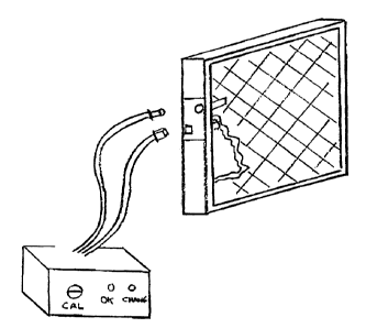
FIGURE 1 is a perspective view of: a filter constructed
in accordance with the teachings of the present invention.
FIGURE 2 is a top plan view, in section, of the filter
illustrated in FIGURE 1.
FIGURE 3 is a detailed perspective view of a sensing
assembly insert which is attached to or incorporated in the
filter illustrated in FIGURE 1.
DETAILED DESCRIPTION OF THE PREFERRED EMBODIMENT
The preferred embodiment, a filter_ generally identified
by reference numeral 10, will now be described with reference
to FIGURES 1 through 3.
Structure and Relationship of Parts:
Take an existing furnace fi7_ter (commercial or
residential) or equipment filter and add two pilot tubes that
extend from the edge of the filter a di:>tance of about 2 to 6
inches with one tube on either side of -the filter medium. The
CA 02371729 2002-02-12
3
tubes would be about 1~" in diameter with about 3/16" opening.
This component made from metal or plastic is incorporated
into the filter to sample the air pressure on either side of
the filter. Every time the filter is changed a new clean set
of sensing tubes are already built into the filter
eliminating the need for maintenance of permanently mounted
sensing tubes.
A sensor that measures differential pressure would be mounted
close by. The sensor would let the user know when the filter
requires changing by a signal (light., buzzer etc). The
sensor can be calibrated for each unit by blocking the
appropriate amount of air flow through the filter with paper
and then turning on the air flow source. This is the point
at which the sensor alarm would go off to indicated it is
time to change the filter.
The sensor is connected to the filter by a set of flexible
tubes the are plugged into the one way connector that ensures
the connection is made correctly.
The sensor can be powered by battery, low or high voltage and
be ready to incorporate into an electronic system for future
applications requiring signal processors for computer
management systems
Operation:
In this patent document, the word "comprising" is used
in its non-limiting sense to mean that items following the
word are included, but items not specifically mentioned are
not excluded. A reference to an element by the indefinite
article "a°' does not exclude the possibility that more than
one of the element is present, unless> the context clearly
requires that there be one and only one of the elements.
CA 02371729 2002-02-12
4
It will be apparent to one ski:Lled in the art that
modifications may be made to the illustrated embodiment
without departing from the spirit and scope of the invention
as hereinafter defined in the Claims.