Note: Descriptions are shown in the official language in which they were submitted.
CA 02371935 2001-12-14
WO 00/78239 PCT/US00/16781
1
RF ABLATION APPARATUS AND METHOD HAVING
ELECTRODE/TISSUE CONTACT ASSESSMENT SCHEME
AND ELECTROCARDIOGRAM FILTERING
BACKGROUND OF THE INVENTION
The invention relates generally to an electrophysiological ("EP") apparatus
and method for providing energy to biological tissue, and more particularly,
to an
EP apparatus and method for assessing the adequacy of contact between an
ablation electrode and biological tissue. The invention also relates to an
apparatus and method for providing energy to biological tissue while
simultaneously monitoring the electrical activity within the tissue.
The heart beat in a healthy human is controlled by the sinoatrial node ("S-
A node") located in the wall of the right atrium. The S-A node generates
electrical signal potentials that are transmitted through pathways of
conductive
heart tissue in the atrium to the atrioventricular node ("A-V node") which in
turn
transmits the electrical signals throughout the ventricle by means of the His
and
Purkinje conductive tissues. Improper growth of, or damage to, the conductive
tissue in the heart can interfere with the passage of regular electrical
signals from
the S-A and A-V nodes. Electrical signal irregularities resulting from such
interference can disturb the normal rhythm of the heart and cause an abnormal
rhythmic condition referred to as "cardiac arrhythmia."
While there are different treatments for cardiac arrhythmia, including the
application of anti-arrhythmia drugs, in many cases ablation of the damaged
tissue can restore the correct operation of the heart. Such ablation can be
performed by percutaneous ablation, a procedure in which a catheter is
percutaneously introduced into the patient and directed through an artery to
the
atrium or ventricle of the heart to perform single or multiple diagnostic,
therapeutic, and/or surgical procedures. In such case, an ablation procedure
is
used to destroy the tissue causing the arrhythmia in an attempt to remove the
electrical signal irregularities or create a conductive tissue block to
restore normal
heart beat or at least an improved heart beat. Successful ablation of the
conductive tissue at the arrhythmia initiation site usually terminates the
CA 02371935 2001-12-14
WO 00/78239 PCT/US00/16781
2
arrhythmia or at least moderates the heart rhythm to acceptable levels. A
widely
accepted treatment for arrhythmia involves the application of RF energy to the
conductive tissue.
In the case of atrial fibrillation ("AF"), a procedure published by Cox et al.
and known as the "Maze procedure" involves continuous atrial incisions to
prevent atrial reentry and to allow sinus impulses to activate the entire
myocardium. While this procedure has been found to be successful, it involves
an intensely invasive approach. It is more desirable to accomplish the same
result
as the Maze procedure by use of a less invasive approach, such as through the
use
of an appropriate EP catheter system providing RF ablation therapy. In this
therapy, transmural ablation lesions are formed in the atria to prevent atrial
reentry and to allow sinus impulses to activate the entire myocardium.
There are two general methods of applying RF energy to cardiac tissue,
unipolar and bipolar. In the unipolar method a large surface area electrode;
e.g.,
a backplate, is placed on the chest, back or other external location of the
patient
to serve as a return. The backplate completes an electrical circuit with one
or
more electrodes that are introduced into the heart, usually via a catheter,
and
placed in intimate contact with the aberrant conductive tissue. In the bipolar
method, electrodes introduced into the heart have different potentials and
complete an electrical circuit between themselves. In the bipolar method, the
flux
traveling between the two electrodes of the catheter enters the tissue to
cause
ablation.
During ablation, the electrodes are placed in intimate contact with the
target endocardial tissue. RF energy is applied to the electrodes to raise the
temperature of the target tissue to a non-viable state. In general, the
temperature
boundary between viable and non-viable tissue is approximately 48 °
Centigrade.
Tissue heated to a temperature above 48 ° C becomes non-viable and
defines the
ablation volume. The objective is to elevate the tissue temperature, which is
generally at 37 ° C, fairly uniformly to an ablation temperature above
48 ° C, while
keeping both the temperature at the tissue surface and the temperature of the
electrode below 100°C.
CA 02371935 2001-12-14
WO 00/78239 PCT/US00/16781
3
In order to produce effective transmural lesions it is necessary to ensure
that the electrodes are in intimate contact with the tissue. Positioning of
the
electrodes is typically done visually under fluoroscopy imaging and is thus
largely
a function of a physician's training and experience. Assessment of adequate
electrode/tissue contact is somewhat of an art and verification, at present,
is
typically inferred through comparison of pre- and post-ablation
electrocardiogram
("ECG") analysis.
The use of impedance as an indication of electrode/tissue contact has been
reported in the treatment of focal arrhythmias, such as ventricular
tachyarrhythmia. In these procedures, a catheter with a single combination
ablation/impedance-measuring tip electrode is inserted into the local blood
pool
within the heart and an impedance measurement is taken. The tip electrode is
then placed at an ablation location and, so as to push the tip electrode deep
into
the cardiac tissue, force is applied along the axis of the catheter. An
impedance
measurement is then taken and compared to the impedance of the blood pool.
This subsequent impedance measurement is referred to as a "contact-assessment"
impedance. A significant increase in the contact-assessment impedance relative
the blood-pool impedance serves as an indication that the tip electrode is in
contact with cardiac tissue.
In this procedure a significant increase in impedance is noted due to the
fact that the tip electrode is pushed deep into the cardiac tissue and is thus
largely
surrounded by tissue, as opposed to blood. While this electrode/tissue contact
assessment technique is effective for the treatment of focal arrhythmias, it
is less
effective for the treatment of non-focal arrhythmias, such as atrial
fibrillation.
Ablation therapy for atrial fibrillation often involves the formation of
transmural
linear lesions. In this form of ablation therapy a linear array of band
electrodes
is placed against the atrial wall. While the band electrodes are held against
the
tissue with some degree of force, a portion of the band electrodes is likely
to
remain in the blood pool. The presence of blood against a portion of the band
electrode affects the impedance measurement and reduces the significance of
the
difference between the blood-pool impedance and the contact-assessment
CA 02371935 2001-12-14
WO 00/78239 PCT/LTS00/16781
4
impedance. Thus, the above-described electrode/tissue contact assessment
technique that relies on the use of a tip electrode forced into the tissue is
ineffective for linear ablation therapy. This known technique is further
ineffective
for linear ablation because it does not account for fluctuations in impedance
measurements which may occur due to movement of electrodes caused by
respiration and heart contractions.
As previously mentioned, in present ablation procedures, once ablation
therapy is completed, the effectiveness of the therapy is verified through
electrocardiogram ("ECG") analysis. Ablation therapy is completed upon the
application of ablation energy for a prespecified time period. Once ablation
therapy is completed, the ablation electrode is disconnected from the ablation
energy source and is reconnected to an ECG amplifier/recorder. The ECG
amplifier/recorder collects electrical data from the heart through the
ablation
electrode. The ECG amplifier/recorder analyzes the electrical data and
produces
signals indicative of the electrical activity through the heart tissue and
particularly
the ablated tissue. This present technique of assessing the effectiveness of
ablation is inconvenient in that it requires ablation therapy be completed
prior to
assessing the ablation results and further requires physical switching from
the
ablation source to the ECG amplifier/recorder.
Hence, those skilled in the art have recognized a need for an RF ablation
apparatus and method for assessing the adequacy of the contact between
biological tissue and an ablation electrode positioned against the tissue but
not
necessarily completely surrounded by tissue. The need for an apparatus and a
method for providing ablation energy to biological tissue while simultaneously
monitoring the electrical activity within the tissue has also been recognized.
The
invention fulfills these needs and others.
SUMMARY OF THE INVENTION
Briefly, and in general terms, the invention is directed to an apparatus and
method for assessing the adequacy of contact between an ablation electrode and
biological tissue. The invention is also directed to an apparatus and method
for
CA 02371935 2001-12-14
WO 00/78239 PCT/US00/16781
providing energy to biological tissue while simultaneously monitoring the
electrical activity within the tissue.
In a first aspect, the invention relates to a method of assessing the
adequacy of contact between an ablation electrode carried by an electrode
device
5 and biological tissue within a biological organ having biological fluid
therein. The
method includes the steps of positioning the ablation electrode in the
biological
fluid; positioning a reference electrode a distance from the first electrode
and the
biological tissue and obtaining a reference impedance value by measuring the
impedance between the ablation electrode and the reference electrode. The
method further includes the steps of moving the ablation electrode to a
position
"proximal", i. e., near or next to, but not necessarily in contact with, the
biological
tissue; obtaining an assessment impedance value by measuring the impedance
between the ablation electrode and the reference electrode; analyzing the
assessment impedance and the reference impedance; and indicating the state of
electrode/tissue contact.
In a more detailed aspect, the step of analyzing the assessment impedance
and the reference impedance includes the step of calculating the percentage
difference between the two impedances. Furthermore, the step of indicating the
state of electrode/tissue contact includes the steps of, when the percentage
difference is approximately 10% or more, indicating substantially complete
electrode/tissue contact; when the percentage difference is in the approximate
range between 5% and 10%, indicating partial electrode/tissue contact; and
when
the percentage difference is less than approximately 5%, indicating no
electrode/tissue contact. In another facet, the reference impedance value is
the
average of a plurality of reference impedance values obtained during a given
time
period. In yet another facet, the assessment impedance value is the average
value
of a plurality of assessment impedance values obtained during a given time
period. In still another detailed facet, the method further includes the step
of,
prior to obtaining an assessment impedance value, positioning an electrical
insulator relative the ablation electrode so that when the ablation electrode
is
CA 02371935 2001-12-14
WO 00/78239 PCT/US00/16781
6
proximal the biological tissue the electrode is interposed between the
electrical
insulator and the tissue.
In a second facet, the invention relates to a method of assessing the
adequacy of contact between a plurality of ablation electrodes carried by an
electrode device and biological tissue within a biological organ having
biological
fluid therein. The method includes the steps of obtaining a reference
impedance
value by positioning the plurality of ablation electrodes in the biological
fluid;
positioning a first reference electrode a distance from the plurality of
ablation
electrodes and the biological tissue; and measuring the impedance between at
least one of the ablation electrodes and the reference electrode. The method
also
includes the step of moving the plurality of ablation electrodes to a position
proximal the biological tissue; and for each ablation electrode, obtaining an
assessment impedance value by positioning a second reference electrode a
distance from the ablation electrode and the biological tissue and measuring
the
impedance between the ablation electrode and the reference electrode;
analyzing
the assessment impedance and the reference impedance; and indicating the state
of electrode/tissue contact.
In a third aspect, the invention relates to a method of assessing the
adequacy of contact between a plurality of ablation electrodes carried by an
electrode device and biological tissue within a biological organ having
biological
fluid therein. The method includes the steps of obtaining a reference
impedance
value by positioning the plurality of ablation electrodes in the biological
fluid;
positioning a first reference electrode a distance from the plurality of
ablation
electrodes and the biological tissue; and measuring the impedance between at
least one of the ablation electrodes and the reference electrode. The method
further includes the step of moving the plurality of ablation electrodes to a
position proximal the biological tissue; obtaining an assessment impedance
value
by measuring the impedance between selected pairs of ablation electrodes;
analyzing the assessment impedance and the reference impedance; and indicating
the state of electrode/tissue contact.
CA 02371935 2001-12-14
WO 00/78239 PCT/US00/16781
7
In a fourth facet, the invention relates to a method of assessing the
adequacy of contact between an ablation electrode and biological tissue within
a moving biological organ having biological fluid therein. The method includes
the steps of positioning the ablation electrode proximal the biological
tissue;
positioning a reference electrode a distance from the ablation electrode and
applying a signal to the ablation electrode during a time period sufficient to
include several movements of the organ. The method further includes the steps
of obtaining a sequence of impedance values by periodically measuring the
impedance between the ablation electrode and the reference electrode during
the
time period and monitoring the sequence of impedance values for variations
indicative of electrode/tissue contact.
In a more detailed aspect, the step of monitoring the sequence of
impedance values for variations indicative of electrode/tissue contact
includes the
steps of obtaining an average impedance value based on a plurality of the
impedance values, calculating the standard deviation of the impedance values
relative the average impedance and calculating a "deviation percentage." The
deviation percentage is the standard deviation over the average impedance,
represented as a percentage. Further included are the steps of, when the
deviation percentage is at least approximately 2%, indicating substantially
complete electrode/tissue contact; when the deviation percentage is in the
approximate range between 1% and 2%, indicating partial electrode/tissue
contact; and when the deviation percentage is less than approximately 1%,
indicating no electrode/tissue contact.
In a fifth facet, the invention relates to a method of assessing the adequacy
of contact between an ablation electrode and biological tissue within a
biological
organ having biological fluid therein. The method includes the steps of
positioning the ablation electrode proximal the biological tissue; positioning
a
reference electrode a distance from the ablation electrode; measuring the
impedance between the ablation electrode and the reference electrode at a
first
frequency and measuring the impedance between the ablation electrode and the
reference electrode at a second frequency. The method further includes the
steps
CA 02371935 2001-12-14
WO 00/78239 PCT/US00/16781
8
of analyzing the first-frequency impedance and the second-frequency impedance
and indicating the state of electrode/tissue contact.
In a more detailed facet, the step of analyzing the first-frequency
impedance and the second-frequency impedance includes the step of calculating
the percentage difference between the two impedances. Furthermore, the step
of indicating the state of electrode/tissue contact includes the steps of,
when the
percentage difference is approximately 10% or more, indicating substantially
complete electrode/tissue contact; when the percentage difference is in the
approximate range between 5% and 10%, indicating partial electrode/tissue
contact; and when the percentage difference is less than approximately 5%,
indicating no electrode/tissue contact. In another facet, the step of
analyzing the
first-frequency impedance and the second-frequency impedance includes the
steps
of calculating the ratio of the two impedances and comparing the ratio to a
known value. Also, the step of indicating the state of electrode/tissue
contact
includes the steps of, when the ratio is approximately equal to the known
value,
indicating no electrode/tissue contact; when the ratio deviates from the known
value by an amount in the approximate range between ~ .1 to ~ .15, indicating
at least partial electrode/tissue contact; and when the ratio deviates from
the
known value by an amount approximately greater than ~ .15, indicating
substantially complete electrode/tissue contact.
In a sixth aspect, the invention relates to an apparatus for assessing the
adequacy of contact between an ablation electrode carried by an electrode
device
and biological tissue within a biological organ having biological fluid
therein. The
apparatus includes a signal generating device providing as output a drive
signal
to the ablation electrode and a reference potential and a reference electrode
spaced from the ablation electrode and responsive to the reference potential.
The
apparatus further includes an impedance measurement device for providing a
reference impedance indicative of the impedance between the ablation electrode
and the reference electrode when the ablation electrode is positioned in the
biological fluid and for providing an assessment impedance indicative of the
impedance between the ablation electrode and the reference electrode when the
CA 02371935 2001-12-14
WO 00/78239 PCT/US00/16'781
9
ablation electrode is positioned proximal the biological tissue; and a
processor
responsive to the reference and assessment impedance signals for analyzing the
impedance signals and indicating the state of electrode/tissue contact.
In a seventh facet, the invention relates to an apparatus for assessing the
adequacy of contact between an ablation electrode carried by an electrode
device
and biological tissue within a biological organ having biological fluid
therein. The
apparatus includes a signal generating device providing as output a drive
signal
to the ablation electrode and a reference signal and a reference electrode
spaced
from the ablation electrode and responsive to the reference signal. The
apparatus
further includes an impedance measurement device for providing a sequence of
assessment impedance values indicative of the impedance between the ablation
electrode and the reference electrode and a processor responsive to the
sequence
of assessment impedance signals for monitoring the sequence of impedance
values for variations indicative of electrode/tissue contact.
In an eighth aspect, the invention relates to an apparatus for assessing the
adequacy of contact between an ablation electrode carried by an electrode
device
and biological tissue within a biological organ having biological fluid
therein. The
apparatus includes a signal generating device providing as output a reference
signal and for a first time period, a first drive signal to the ablation
electrode, the
first drive signal having a first amplitude and first frequency, the signal
generating
device also providing as output for a second time period, a second drive
signal to
the ablation electrode, the second drive signal having a second amplitude and
a
second frequency. The apparatus further includes a reference electrode spaced
from the first electrode and responsive to the reference signal; an impedance
measurement device for producing as output a first assessment impedance signal
indicative of the impedance between the ablation electrode and reference
electrode during the first time period and a second assessment impedance
signal
indicative of the impedance between the first and second electrodes during the
second time period and a processor responsive to the first and second
assessment
impedance signals for comparing the impedances to a predetermined value
indicative of electrode/tissue contact.
CA 02371935 2001-12-14
WO 00/78239 PCT/US00/16781
In a ninth facet, the invention relates to a method of providing ablation
energy to biological tissue through an electrode device having at least one
electrode while monitoring the electrical activity of the tissue. The method
includes the steps of positioning the at least one electrode proximal the
tissue;
5 applying ablation power to the at least one electrode through a first lead,
the
ablation power comprising a high frequency component and receiving, from the
electrode and through the first lead, a feedback signal indicative of the
electrical
activity in the tissue. The method also includes the steps of filtering the
feedback
signal to remove any high frequency components and providing the filtered
10 feedback signal to an instrument through a second lead.
In a tenth aspect, the invention relates to an apparatus for providing
ablation power to biological tissue through an electrode device having at
least
one electrode positioned proximal the tissue. The apparatus includes a
generator
producing ablation power having a high-frequency component; a high-frequency
filter; a first lead presenting the ablation power to the at least one
electrode and
the filter, the first lead further presenting a feedback signal from the
electrode to
the filter and a second lead presenting a filter output to an instrument.
In an eleventh facet, the invention relates to an apparatus including a
generator producing a plurality of ablation power signals, each having a high
frequency component; a plurality of high-frequency filters; an electrode
device
having a plurality of electrodes; a plurality of first leads, each presenting
one of
the ablation power signals to one of the electrodes and one of the filters,
the first
lead further presenting a feedback signal from the electrode to the filter;
and a
plurality of second leads, each presenting a filter output to an instrument.
These and other aspects and advantages of the invention will become
apparent from the following detailed description and the accompanying
drawings,
which illustrate by way of example the features of the invention.
BRIEF DESCRIPTION OF THE DRAWINGS
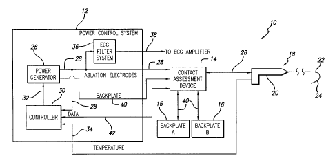
FIGURE 1 is a schematic block diagram of an ablation apparatus including
a power control system ("PCS") with an electrocardiogram ("ECG") filter
system,
a contact assessment device ("CAD"), a catheter system and backplates;
CA 02371935 2001-12-14
WO 00/78239 PCT/US00/16781
11
FIG. 2, is a diagram of the catheter system of FIG. 1 including a handle and
a catheter sheath having a preformed distal segment carrying a linear array of
electrodes;
FIG. 3 is a detailed schematic block diagram of a portion of the distal
segment of FIG. 2, depicting a tip electrode and several band electrodes;
FIGS. 4-1 and 4-2 form a block diagram presenting more detail of a PCS
including phase angle control, duty cycle control and impedance and
temperature
monitoring circuitry and a CAD including square-wave conditioning, current
sense
and relay control circuitry;
FIGS. 5-1 and 5-2 form a diagram of a multi-channel ablation apparatus
wherein a single PCS microprocessor controls the application of ablation
energy
to each channel individually and a single CAD microprocessor controls the
monitoring of impedances between select electrodes and/or backplates;
FIGS. 6A, 6B, 6C, 6D, 6E and 6F form a schematic diagram of an
embodiment of a PCS including an ECG filter, with FIG. 6A showing how FIGS.
6B, 6C, 6D, 6E and 6F are related;
FIGS. 7-1 and 7-2 form a schematic block diagram of an embodiment of
a CAD;
FIGS. 8a is a representation of the distal segment of the catheter system of
FIG. 2 positioned within a biological site and floating in the local blood
pool;
FIGS. 8b is a representation of the distal segment of the catheter system
of FIG. 2 positioned within a biological site and proximal biological tissue
with
most of the electrodes in a blood pool;
FIGS. 8c is a representation of the distal segment of the catheter system of
FIG. 2 positioned within a biological site and proximal biological tissue with
each
of the electrodes in intimate contact with the tissue;
FIG. 9a is a diagram of a portion of the distal segment of a catheter system
having full-ring band electrodes partially coated with an electrically
insulating
but thermally conductive material;
FIG. 9b is a diagram of a portion of the distal segment of a catheter system
having half-ring band electrodes positioned on the outside radius of
curvature;
CA 02371935 2001-12-14
WO 00/78239 PCT/US00/16781
12
FIG. 9c is a diagram of a portion of the distal segment of a catheter system
having an outer sheath comprising an insulating material partially surrounding
the band electrodes;
FIG. 10A is a three dimensional representation of an ablation apparatus
having a linear array of band electrodes in contact with a biological site
with a
backplate at the opposite side of the biological site, in which the phase
angle
difference between adjacent electrodes of the linear array is zero degrees;
FIGS. lOB through lOD depict, along the x, y, and z axes shown, the depth
of the lesions formed by the ablation apparatus of FIG. 10A showing that the
apparatus acts as a unipolar device with multiple electrodes and the resulting
lesions are discontinuous;
FIG. 11A is a three dimensional representation of an ablation apparatus
having a linear array of band electrodes in contact with a biological site
with a
backplate at the opposite side of the biological site, in which the phase
angle
difference between adjacent electrodes is 180 degrees;
FIGS. 11B through 11D depict, along the x, y, and z axes shown, the
continuity and depth of a lesion formed by the ablation apparatus of FIG. 10A
showing that the apparatus acts as a bipolar device with no significant amount
of
current flowing to the backplate;
FIG. 12A is a three dimensional representation of an ablation apparatus
having a linear array of band electrodes in contact with a biological site
with a
backplate at the opposite side of the biological site, in which the phase
difference
between adjacent electrodes is approximately 90 degrees; and
FIGS. 12B through 12D depict, along the x, y, and z axes shown, the
continuity and depth of a lesion formed by the ablation apparatus of FIG. 11A
showing the greater depth of lesion resulting from the phase angle difference.
DETAILED DESCRIPTION OF PREFERRED EMBODIMENTS
Turning now to the drawings, in which like reference numerals are used
to designate like or corresponding elements among the several figures, in FIG.
1
there is shown an apparatus 10 for use in ablation therapy of a biological
site,
e. g., the atrium or ventricle of the heart. The apparatus 10 includes a power
CA 02371935 2001-12-14
WO 00/78239 PCT/US00/16781
13
control system 12, a contact assessment device ("CAD") 14, a pair backplates
16
and a catheter system 18. The catheter system 18 includes a handle 20 and a
steerable catheter sheath 22 having a distal segment 24. The distal segment 24
carries at least one electrode (not shown). The distal segment 24 is capable
of
being percutaneously introduced into a biological site.
The power control system 12 comprises a power generator 26, that may
have any number of output channels through which it provides power or drive
28.
The operation of the power generator 26 is controlled by a controller 30 which
outputs control signals 32 to the power generator 26. The controller 30
monitors
the power 28 provided by the power generator 26. In addition, the controller
30
also receives temperature signals 34 from the catheter system 18. Based on the
power 28 and temperature signals 34 the controller 30 adjusts the operation of
the power generator 26.
The power 28 is input to the CAD 14 and to an electro-cardiogram (ECG)
filter system 36 contained within the power control system 12. As explained
further below, the ECG filter system 36 filters the power 28 to provide ECG
signals 38 for ECG analysis. The ECG filter system 36 outputs the ECG signals
38
to the contact assessment device 14. The ECG signals 38 are then passed to an
ECG amplifier (not shown) . The contact assessment device 14 provides the
power
28 to the catheter system 18. The CAD 14 also provides a return path 40 from
the backplates 16 to the power generator 26. As explained further below, the
CAD 14 collects data 42 from the catheter system 18 and provides it the
controller
30. This data 42 is used to assess the adequacy of the contact between the
catheter system 18 electrode or electrodes (not shown) and the biological
tissue
to be ablated.
As shown in FIGS 2. and 3, the distal segment 24 of the catheter system
18 includes an electrode device 44 (FIG. 3). The electrode device 44 is shown
in
schematic form with the components drawn to more clearly illustrate the
relationship between the components. A preferred embodiment of the electrode
device 44 includes twelve band electrodes 46 arranged in a substantially
linear
array along the distal segment 24 of the catheter sheath 22. The electrode
device
CA 02371935 2001-12-14
WO 00/78239 PCT/US00/16781
14
44 may include a tip electrode 48. (For clarity of illustration, only four
band
electrodes 46 are shown in FIG. 3 although as stated, a preferred embodiment
may include many more.) The band electrodes 46 are arranged so that there is
space 50 between adjacent electrodes. In one configuration of the electrode
device 44, the width of the band electrodes 46 is 3 mm and the space 50
between
the electrodes is 4 mm. The total length of the electrode device 44, as such,
is
approximately 8 cm.
The arrangement of the band electrodes 46 is not limited to a linear array
and may take the form of other patterns. A substantially linear array is
preferred
for certain therapeutic procedures, such as treatment of atrial fibrillation,
in
which linear lesions of typically 4 to 8 cm in length are desired. A linear
array is
more easily carried by the catheter sheath 22 and also lessens the size of the
catheter.
The band electrodes 46 are formed of a material having a significantly
higher thermal conductivity than that of the biological tissue to be ablated.
Possible materials include silver, gold, chromium, aluminum, molybdenum,
tungsten, nickel, platinum, and platinum/10% iridium. Because of the
difference
in thermal conductivity between the band electrodes 46 and the tissue, the
electrodes cool off more rapidly in the flowing fluids at the biological site.
The
power supplied to the band electrodes 46 may be adjusted during ablation to
allow for the cooling of the electrodes while at the same time allowing for
the
temperature of the tissue to build up so that ablation results. The band
electrodes
46 are sized so that the surface area available for contact with fluid in the
heart,
e. g., blood, is sufficient to allow for efficient heat dissipation from the
electrodes
to the surrounding blood. In a preferred embodiment, the electrodes 46 are 7
French (2.3 mm in diameter) with a length of 3 mm.
Associated with the electrode device 44 are thermal sensors 52 for
monitoring the temperature of the electrode device 44 at various points along
its
length. In one embodiment, each band electrode 46 has a thermal sensor 52
mounted to it. Each thermal sensor 52 provides a temperature signal 34 (FIG.
1)
to the controller 30 which is indicative of the temperature of the respective
band
CA 02371935 2001-12-14
WO 00/78239 PCT/L1S00/16781
electrode 46 (FIGS. 2 and 3) at that sensor. In another embodiment of the
electrode device 44 a thermal sensor 52 is mounted on every other band
electrode
46. Thus for a catheter having twelve electrodes, there are thermal sensors on
six
electrodes. In yet another embodiment of the electrode device 44 every other
5 electrode has two thermal sensors 52. In FIG. 3, which shows an embodiment
having one thermal sensor for each electrode, there is shown a single power
lead
54 for each electrode 46 to provide power to each electrode for ablation
purposes
and two temperature leads 56 for each thermal sensor 52 to establish the
thermocouple effect.
10 Turning now to FIGS. 4-1 and 4-2, a block diagram of an ablation
apparatus comprising a CAD 14 and a single channel power control system 12 for
use with a catheter system having a single band electrode 46 is presented. As
will be discussed in relation to other figures, an ablation apparatus may
include
a mufti-channel power control system 12 for use with a catheter system having
15 a plurality of band electrodes 46. In FIG. 4-1, a power control system
("PCS")
microprocessor 58, which is part of the controller 30 (FIG. 1), provides a
duty
cycle control signal 60 to a duty cycle generator ("DCG") 62. In this case,
the
duty cycle generator 62 receives the control signal 60 by an 8-bit latch 64.
The
latch 64 provides an 8-bit signal 66 to a duty cycle comparator 68. The
comparator 68 compares the 8-bit signal 66 to a count 78 from an 8-bit duty
cycle
counter 70 and if the count is the same, provides a duty cycle off signal 72
to the
duty cycle gate 74. The gate 74 is connected to a frequency source ("FS") 76,
such as an oscillator that produces 500 kHz. When the gate 74 receives the
duty
cycle off signal 72 from the comparator 68, it stops its output of the
frequency
source signal through the gate and no output exists.
At a frequency of 500 kHz, an 8-bit control has a period or time frame of
0.5 msec. At a fifty-percent duty cycle, the electrode is in the off period
only 0.25
msec. To allow for greater cooling of the electrode, the period or time frame
is
lengthened by use of a prescalar 80 interposed between the frequency source 76
and the counter 70. In one embodiment, the prescalar 80 lengthens the period
to 4 msec thus allowing for a 2 msec off period during a fifty-percent duty
cycle.
CA 02371935 2001-12-14
WO 00/78239 PCT/US00/16781
16
This results in a sufficient cooling time for the very thin band electrodes
discussed
above. Other lengths of the period may be used depending on the circumstances.
It has been found that a ten percent duty cycle is particularly effective in
ablating
heart tissue. The combination of the application of high peak power, a ten
percent duty cycle, the use of high thermal conductivity material in the band
electrodes, and fluids flowing past the band electrodes which have a cooling
effect
on the electrodes result in a much more effective application of power to the
tissue. Ablation occurs much more rapidly.
A terminal count detector 82 detects the last count of the period and sends
a terminal count signal 84 to the gate 74 which resets the gate for continued
output of the frequency source signal. This then begins the on period of the
duty
cycle and the counter 70 begins its count again. In one preferred embodiment,
the duty cycle is set at fifty percent and the 8-bit latch is accordingly set
to 128.
In another embodiment, the duty cycle is set at ten percent.
A programmable logic array ("PLA") 86 receives phase control signals 88
from the PCS microprocessor 58 and controls the phase of the frequency source
76 accordingly. In one embodiment, the PLA 86 receives the terminal count
signal 84 from the terminal count detector 82 and only permits phase changes
after receiving that terminal count signal.
The output signal from the gate 74 during the on-period of the duty cycle
is provided to a binary power amplifier ("BPA") 90 that increases the signal
to a
higher level, in this case, 24 volts. The amplified signals are then filtered
with a
band pass filter ("BPF") 92 to convert the somewhat square wave to a sine
wave.
The band pass filter 92 in one embodiment is centered at 500 kHz. The filtered
signal is then provided to an isolated output transformer ("IOT") 94 that
amplifies
the signal to a much higher level, for example 350 volts peak-to-peak. This
signal
is then sent to a relay interconnect ("RI") 96 before it is provided as a
power
output signal OUTn 28 to the CAD 14 and the ECG filter system 36. At the CAD
14, the power output signal 28 is fed thru a CAD feedthru 126 to an electrode
46.
The power output signal 28 from the isolated output transformer 94 is
monitored in one embodiment to determine the impedance at the electrode 46.
CA 02371935 2001-12-14
WO 00/78239 PCT/US00/16781
17
In the embodiment shown in FIGS. 4-1 and 4-2, a voltage and current monitor
("VCM") 98 is used. The monitor signal 100 is converted to digital form by an
A-
to-D converter ("ADC") 102 and provided to the PCS microprocessor 58. As
previously mentioned, some or all of the electrodes 46 may include a thermal
sensor 52 (FIG. 3) that provides temperature signals 34 (FIG. 4-2) which are
used
to determine the temperature at the electrode 46. In one embodiment of the
invention, the power 28, in conjunction with the temperature signals 34, are
used
to determine the temperature at the electrode 46. Both the temperature signals
34 and the power 28 pass through a temperature filter ("FL") 104 before being
sent to the PCS microprocessor 58. In the alternative, the temperature filter
104
is contained in a printed circuit board separate from the controller 30 and
contains its own processor. In either case, the filter 104 filters out any RF
noise
present in the power 28 so that the signal may be used for temperature
monitoring purposes. In another embodiment, the PCS microprocessor 58
monitors the power 28 and temperature signals 34 only during the off periods
of
the power 28 duty cycle. Accordingly, negligible RF noise is present in the
power
line and filtration is not necessary. In either embodiment, the PCS
microprocessor 58 may alter the duty cycle of the power 28 in response to
either
or both of the impedance or temperature signals.
At the ECG filter system 36 the power signal 28 is filtered to remove the
500kHz frequency component, thus providing an ECG signal 38 that is free of
high frequency interference. The ECG signal thus comprises low frequency,
typically between 0 and 250 Hz, electrical signals detected in the biological
tissue
by the ablation electrode. As explained below, the ECG filter system 36 allows
for
continuous ECG analysis of the tissue to occur simultaneously with the
application of ablation energy.
The CAD 14 includes a CAD microprocessor 106 that generates a multi-
frequency initial square-wave drive signal 108. While the following describes
the
drive signal 108 as being a square-wave it is understood that the drive signal
may
have forms other then a square wave. The initial drive signal 108 is input to
a
square wave conditioning circuit 110. The conditioning circuit 110 operates to
CA 02371935 2001-12-14
WO 00/78239 PCT/US00/16781
18
center the square-wave drive signal 108 around zero volts and to reduce the
amplitude of the drive signal to a non-pacing level, i. e., a level
insufficient to
induce pacing of the heart.
The conditioned drive signal 112 is then input to a current sense circuit
114. The current sense circuit 114 provides voltage signals 112, 124 to the
CAD
microprocessor 106 which are used to calculate the current passing through the
current sense circuit, i. e., the drive current. The conditioned drive signal
112 is
input to line-A relay circuitry 116. The line-A relay circuitry 116 is
controlled by
the CAD microprocessor 106. In a single-electrode catheter system, as depicted
in FIG. 4, the conditioned drive signal 112 is provided to the single
electrode 46,
which during contact assessment, acts as a drive electrode.
A reference electrode 120, positioned a distance from the drive electrode
46, provides a reference point for impedance measurement purposes. In a single-
electrode device, the reference electrode 120 is typically the backplates 16.
Alternatively, the catheter may carry, in addition to the single drive
electrode 46,
a dedicated reference electrode 120. This dedicated reference electrode 120
may
be tied, through a line-B relay circuit 122, to a CAD ground or to a signal of
known voltage VEI. The conditioned drive signal 112 is fed back to the CAD
microprocessor 106 where it is digitized and sent to the PCS microprocessor
58.
Based on the voltage value of the fed back drive signal, the known voltage
value
of the reference electrode (patient ground, instrument ground or known
voltage),
and the previously calculated drive current, the PCS microprocessor 58
calculates
the impedance between the drive electrode 46 and the reference electrode 120.
Referring now to FIGS. 5-1 and 5-2, a block diagram of an ablation
apparatus having a CAD and a multi-channel power control system for use with
a catheter system having a plurality of ablation electrodes 46 is shown.
Although
only three complete channels are shown, the apparatus comprises many more as
indicated by the successive dots. Those channels are not shown in FIGS. 5-1
and
5-2 to preserve clarity of illustration.
The single PCS microprocessor 58, which again is part of the controller 30
(FIG.1), controls the duty cycle and the phase of each channel individually in
this
CA 02371935 2001-12-14
WO 00/78239 PCT/US00/16781
19
embodiment. Each channel shown comprises the same elements and each
channel produces its own power output signal 28 (OUTl, OUT2, through OUTn
where "n" is the total number of channels) on respective electrode leads (LEAD
1, LEAD 2, through LEAD n where "n" is the total number of leads) to an
individual ECG filter 128 and the CAD feedthru 126 to the electrode 46.
The CAD includes a plurality of electrode relays 130. Input to each of the
electrode relays 130 is a line A 132, a line B 134 and relay control line 136.
The
line A 132 may carry either one of the conditioned drive signal 112 or an
externally applied signal VE1 having a known voltage. The selection of which
signal is made available on line A 132 is controlled by the line-A relay 116
under
the guidance of the CAD microprocessor 106. The line A 132 provides the
conditioned drive signal 112 or the external signal VE1 to a selected one of
the
electrodes 46 which then acts as the drive electrode, for contact assessment
purposes.
Line B 134 provides a signal to one of the electrodes 46, other then the
electrode which is acting as the drive electrode. Line B 134 may provide
either
one of the CAD ground, an externally applied signal VE2 having a known
voltage,
or the backplatesl6. In a bipolar operation, where the impedance is measured
between any pair of electrodes 46, line B 134 provides a connection path for
one
of the electrodes to either CAD ground or an externally applied signal of a
known
voltage VE2. In a unipolar operation, the line B 134 provides a connection
path
for one of the electrodes 46 to the backplatesl6. The selection of which
signal is
made available on line B 134 is controlled by the line-B relay 122 under the
guidance of the CAD microprocessor 106.
Operation of the electrode relays 130 is controlled by relay control
circuitry 118 under the guidance of the CAD microprocessor 106. Operation of
the line-A relay 116 and the line-B relay 122 is controlled directly by the
CAD
microprocessor 106. As explained further below, the CAD may be programmed
to control the relays 116, 118, 130 to provide impedance measurements between
any pair of electrodes 46 and between any one of the electrodes 46 and
CA 02371935 2001-12-14
WO 00/78239 PCT/US00/16781
backplates 16. As explained below, these impedance measurements are used to
assess the adequacy of electrode/tissue contact.
With reference now to FIGS. 6A through 6F, a schematic diagram of an
embodiment of the power control system 12 of FIG. 2 is presented in FIGS. 6B
5 through 6F while FIG. 6A shows how FIGS. 6B through 6F should be oriented in
relation to each other. The frequency source 76 provides a signal 138,
typically
at 500 kHz with a phase angle controlled by the PCS microprocessor 58 through
the PLA 86, to the duty cycle generator 62. The duty cycle generator 62
modulates the frequency source signal 138 to produce the selected duty cycle
in
10 accordance with the duty cycle control signal 60 as previously described.
The
duty cycle generator 62 outputs two signals 140 and 142 to the binary power
amplifier 90. A dual MOSFET driver U2 receives the signals, converts their 5V
level to a 12V level, and sends each to a transformer T2 which transforms the
signals into 24 V peak-to-peak power.
15 The 24V power is then sent to a mufti-state driver 144 which includes a
configuration of FETs Q2, Q3, Q4, and Q5. During a conducting state of the
driver 144, which is typically the on period of the power, these FETs Q2
through
Q5 conduct and forward the power to a bandpass filter 92 comprising a series
LC
network. During a high-impedance state of the driver 144, which is typically
20 during the off period of the power, the FETs Q2 through Q5 are
nonconducting
and no power is sent to the bandpass filter 92. Instead the FETs Q2 through Q5
present a high impedance load to any signals received through the electrode
46.
Typically the load impedance on the FETs Q2 through Q5 presented by the
circuit
following the FETs , the electrode, and the tissue is approximately 150 S~ but
transformed through the output transformer T3, it presents a load impedance to
the FETs Q2-Q5 of approximately 0.5 to 1 S2. In the off state, the FETs
present
an impedance of approximately 250 S2 which is large in comparison to the
transformed load impedance of approximately 0.5 to 1 S~. Therefore, very
little
power flows when the FETs are in the off state.
The bandpass filter 92 operates to shape the output signal provided by the
binary amplifier 90 from a square wave to a sinusoidal wave. The filtered
signal
CA 02371935 2001-12-14
WO 00/78239 PCT/US00/16781
21
146 then passes to the isolated output section 94 where it is step-up
transformed
to 350 volt peak-to-peak sinusoidal power at T3. The power is then split into
two
identical power signals OUT1A, OUT1B. Each of OUT1A and OUT1B is provided
to an LC series resonant circuit 148 which ensures that the signal is at or
near the
ablation frequency, e. g., approximately 500 kHz. Each of OUT1A and OUT1B is
then provided to two or more respective band electrodes 46 on the output lines
LEADlA, LEAD1B.
During ECG analysis, feedback signals from the band electrodes 46 are
input to an ECG filter 128 comprising a 4''' order Butterworth filter. These
feedback signals comprise generally low-frequency signals present in the
biological tissue. Also input to the filter 128 is the output of the LC series
resonant circuit 148, which is essentially the high-frequency ablation signal,
which is typically around 500kHz. The ECG filter 128 filters out the high-
frequency ablation signal, leaving only lower frequency components. This
signal
is then fed to an ECG amplifier/recorder where the ECG activity of the
biological
tissue may be monitored.
The isolated output section 94 also includes relays 150 that may be
individually opened to remove the power signals OUT1A, OUT1B from the
electrode leads LEAD 1A, LEAD 1B when an alert condition is detected, such as
high temperature or high impedance at the respective electrode 46. As
previously
mentioned these conditions are determined by the PCS microprocessor 58 which
receives signals indicative of the temperature and impedance at each of the
electrodes 46.
The power from the isolated output section 94 is monitored and
representative signals are supplied to an RF voltage and current monitor 98
where in this case, the voltage and current of each output signal are measured
to
determine the impedance of the particular channel. The measured signals are
sent to an A-to-D converter 102 (FIG. 2) before being sent to the PCS
microprocessor 58 for impedance monitoring. If the impedance is above a
threshold level indicative of blood clotting or boiling, the PCS
microprocessor 58
sends a signal to the duty cycle generator 62 to reduce or discontinue the
duty
CA 02371935 2001-12-14
WO 00/78239 PCT/US00/16781
22
cycle of the power OUT1A, OUT1B and thus lower the effective power delivered
to the electrodes 46.
Similarly, the temperature at the electrodes 46 is determined by
monitoring the power and temperature signals and measuring the voltage
difference between the signals. As previously mentioned, in one embodiment of
the invention, these signals pass through a filter 104 (FIG. 2) before being
sent
to the PCS microprocessor 58. The voltage value is converted to a temperature
and if the temperature is above a threshold level the duty cycle of the power
14
is reduced. In the case where a single lead is used to provide a signal which
is
used to determine the temperature as well as provide power to the electrode
46,
the signal from the lead is received on temperature leads 87, 89 connected at
the
output side of the relays 150.
As shown in FIG. 5, the duty cycle of each electrode 46 may be individually
controlled by the PCS microprocessor 58. As previously mentioned, based on the
temperature at an electrode 46 and the current and voltage of the output
signal
provided to an electrode, the duty cycle of the output signal may be adjusted.
For
example, one electrode 46 may have a temperature requiring a duty cycle of ten
percent, while another electrode may have a temperature which allows for a
fifty
percent duty cycle. In an embodiment in which every other electrode 46 has a
thermal sensor 52, the electrodes are grouped in pairs with each electrode in
the
pair having the same duty cycle.
Referring to FIGS. 6B through and 6E, the following devices are shown:
Device Part No. Manufacturer
U1 GAL6002B Lattice
U2 SN75372 numerous
Ql 1RFZ34N numerous
Q2, Q3, Q4, Q5 1RFZ44N numerous
Q7, Q8, Q9 MPF6601 numerous
R3, R5 1S2 numerous
T1, T4 CMI-4810 Corona Magnetics, Inc.
T2 GFS97-0131-1 GFS Manufacturing
CA 02371935 2001-12-14
WO 00/78239 PCT/US00/16781
23
T5 CMI-4809 Corona Magnetics, Inc.
The transformer denoted by "T3" is a 1:12 turns ratio, single turn primary,
step
up transformer wound on a TDK core PC50EER23Z.
With reference now to FIGS. 7-1 and 7-2, the CAD microprocessor 106
provides a dual frequency, 5V peak-to-peak square wave at the "square" output
108. The frequencies of the signal are set by the CAD microprocessor 106 and
may be changed by reprogramming the microprocessor. In a preferred
embodiment, these frequencies are lOkHz and 500kHz. The time duration of
each frequency is also set by the CAD microprocessor 106. The signal is
typically
set at each frequency for a portion of the total duration of the signal. For
example, if the signal is output for 10 seconds, the signal is at lOkHz for 5
seconds and at 500kHz for the remaining 5 seconds.
The 5V square wave is input the square wave conditioning circuitry 110
that includes an offset voltage follower 152. The offset voltage follower 152
buffers and centers the 5V square wave to ~ 2.5 V. A voltage divider at the
output of the voltage follower 152 limits the ~ 2.5 V square wave signal to a
~
50mV peak-to-peak square wave signal 112. This dual-frequency, 50 mV signal
112 serves as a drive signal and, prior to any impedance measurements, is
available at both pins VRl and VR2 of the CAD microprocessor 106.
The CAD 14 includes relay circuits 116, 122, 130 that allows for bipolar
impedance measurements to be taken between select pairs of electrodes 46 (FIG.
5). The relay circuits 116, 122, 130 (FIG. 7-2) also allow for unipolar
measurements to be taken between any of the electrodes 46 (FIG. 5) and the
backplates 16. The states of the relays 116, 122, 130 are controlled by the
CAD
microprocessor 106. The CAD microprocessor controls relay-13A 116 and relay-
13B and relay 25 122 directly. The states of the electrode relay circuits 130
are
controlled through three 8-bit latch circuits 154. Data bits DBO-DB7 for
controlling the electrode relays 130 are stored in the EPROM 156. The data
bits
DBO-DB7 are selected by the CAD microprocessor 106 through address line 186.
The CAD microprocessor 106 addresses a portion of the EPROM 156 through an
additional 8-bit latch 158. Upon selection, the data bits DBO-DB7 are sent to
CA 02371935 2001-12-14
WO 00/78239 PCT/LTS00/16781
24
each of the 8-bit latches 154. Strobe A, B, C lines 188 from the generic array
logic (GAL) 160 control the activation state of the latches 154. The GAL 160,
in
turn, is controlled by the CAD microprocessor 106 through address line 190.
Relay 13A 116 provides for the availability of the either the drive voltage
VR2 or an external voltage VEl over line A. The external voltage VE1 is used
to
drive the electrodes 46 with a voltage different then the ~ 50mV square wave
signal. Any non-pacing voltage may be used to drive the electrode 46 to obtain
impedance measurements. For example, voltages between 20mV and 200mV
may be used in electrode/tissue contact assessment.
The closing of one of the line-A electrode relays 130 connects either VR2
or VE1 to one of the electrodes 46 which then acts as a drive electrode for
impedance measurement purposes. Once this relay 130 is closed, the feedback
signal from the drive electrode experiences a slight voltage drop. As
explained
further below, this voltage drop is used to sense the current passing between
the
drive electrode and another selected electrode, i. e., the reference
electrode.
During the bipolar mode of impedance measurement, relay 13B and relay
122 cooperate to provide either CAD ground or an external, non-ground
voltage VE2. The closing of one of the line-B electrode relays 130, connects
an
electrode 46 to CAD ground or VE2. This electrode 46 acts as the reference
20 electrode. During the unipolar mode of impedance measurement, relay 13B and
relay 25122 cooperate to provide access to the backplatesl6 (FIG. 5) The
closing
of one of the line-B electrode relays 130, connects an electrode 46 to the
backplates. This electrode 46 acts as the reference electrode.
The voltages VRl and VR2 are inputs to an analog-to-digital converter in
25 the CAD microprocessor 106. These voltages are digitized by the CAD
microprocessor 106 and transmitted through the RS232 chip 162 to the PCS
microprocessor 58 (FIG. 5). Initially, the PCS microprocessor 58 first
determines
the current passing through the current sense circuit 114 (FIG. 7) based on
the
difference between the voltage of the feedback signal VR2 and the drive signal
VRl and the known value of the resistor R4 contained in the current sense
circuit
CA 02371935 2001-12-14
WO 00/78239 PCT/US00/16781
112. This current is essentially the same as the current passing between the
drive
electrode and the reference electrode.
Using this current value and the voltage difference between the drive
electrode and the reference electrode, the impedance between the drive
electrode
5 and the reference electrode is calculated. The voltage difference between
the
drive and reference electrodes VD_R is usually around 50mV when the drive
electrode is maintained at VRl, i. e., substantially 50mV, and the reference
electrode is connected to either CAD ground or the backplates, i. e., patient
ground. Alternatively, if the drive electrode is maintained at the externally
10 applied voltage VE1 then VD_R may be a value other than 50mV. This value
depends on whether the reference electrode is connected to CAD ground, patient
ground or another known voltage VE2.
Referring to FIGS. 7-1 and 7-2, the following devices are shown. Note that
each of relays lA-13B and 25 are identical. Accordingly, the parts for only
relay
15 1A are listed.
Device Part No. Manufacturer
D26 LM385-2-5 Texas Instruments
D27, D28 1N5817 Motorola
Rl, R3 1.8k S2 numerous
20 R2 3k S2 numerous
R4, R7 lOk S~ numerous
R5 5.6k S2 numerous
R6 300 S~ numerous
Q28 TN0604N3 SuperTex
25 U11A LF353 Texas Instruments
Relay 1A:
diode Dx 1N4004 numerous
transistor Qx TN0604N3 numerous
relay T7595D-112-12 Potter & Bromfield
In operation, prior to the application of RF ablation energy, the ablation
apparatus of the present invention provides for electrode/tissue contact
CA 02371935 2001-12-14
WO 00/78239 PCT/US00/16781
26
assessment. With reference to FIGS. 8a and 8c, once the distal segment 24 is
positioned within the biological site, e. g., the atrium of the heart,
impedance data
is collected and analyzed to determine the adequacy of electrode/tissue
contact.
In one embodiment of the invention, the distal segment 24 is placed near
or within the atrium and positioned under fluoroscopy such that at least one
of
the electrodes 46 is completely within the local blood pool 164, as shown in
FIG.
8a. Under CAD microprocessor 106 control, one of the electrodes 46 in the
local
blood pool 164 is selected to act as the drive electrode while either the
backplates
16, or one of the other electrodes 46 in the blood pool is selected to act as
the
reference electrode. For example, as shown in FIG 8a, electrode F may be
selected as the drive electrode while either the backplate 16 or electrode H
may
be selected as the reference electrode. The impedance between the drive
electrode and the reference electrode is then determined by applying a drive
signal to the drive electrode and a reference potential to the reference
electrode.
As previously described this reference potential is most likely to be CAD
ground
or patient ground. This initial calculation provides an impedance measurement
of the local blood pool 164 which serves as a reference against which
subsequent
impedance measurements are compared to assess electrode/tissue contact.
Experimentation has shown that impedance measurements between
electrodes placed within biological fluid, e. g., blood, are generally lower
than
those of electrodes which contact biological tissue. With this as a guideline,
once
the reference impedance is determined, the distal segment 24 is repositioned,
once again under fluoroscopy, such that the previously selected drive
electrode,
e. g. H, is positioned at a location perceived, under fluoroscopy, to be close
to or
in contact with tissue, as shown in FIGS. 8b and 8c. The impedance between the
drive electrode and a selected reference electrode is calculated. The
reference
electrode is usually, although not necessarily, the same reference electrode
used
to calculate the reference impedance. This new impedance is referred to as an
"assessment" impedance.
The assessment impedance and the reference impedance are then analyzed
within the PCS microprocessor. The differences between the assessment
CA 02371935 2001-12-14
WO 00/78239 PCT/US00/16781
27
impedance and the reference impedance is monitored for significant variations
which may be indicative of tissue contact. These difference may be based on a
simple mathematical difference between the impedances or may be based on a
percentage change in the impedance. Experimentation has shown that an
assessment impedance increase, relative the reference impedance, of between
10% and 20% is indicative of electrode/tissue contact.
In a preferred embodiment, the PCS microprocessor 58 continuously
calculates both reference and assessment impedances for a given period of time
and determines the average impedance for each. This period of time may be, for
example, 10 seconds. Contact assessment is then based on the average
impedances. In using average values, the apparatus accounts for fluctuations
in
impedance values that may occur due to displacement of the electrodes caused
by respiration and/or heart contractions.
The PCS microprocessor analyzes the assessment impedance and the
reference impedance and provides an indication of the state of the
electrode/tissue contact. This indication may be provided on the front panel
of
the power control system through a display device. The display device may be
in
the form of a percentage indicative of the degree of confidence of
electrode/tissue
contact, with, for example, 100% indicating complete electrode/tissue contact
and decreasing percentages indicating less electrode/tissue contact. Similar
information may also be presented graphically by, for example, a bar graph.
The PCS microprocessor calculates the percentage difference between the
two impedances and provides the following indications. When the percentage
difference is at least approximately 10% the PCS microprocessor indicates that
substantially complete electrode/tissue contact exists. The larger the
percentage
difference, the greater the level of confidence of electrode/tissue contact.
When
the percentage difference is in the approximate range between 5% and 10% the
PCS microprocessor indicates that partial electrode/tissue contact exists.
When
the percentage difference is less than approximately 5% the PCS microprocessor
indicates that there is no electrode/tissue contact.
CA 02371935 2001-12-14
WO 00/78239 PCTNS00/16781
28
The ablation apparatus 10 is particularly well suited for use with a catheter
system having a linear array of band electrodes 46 at its distal segment 24.
With
continued reference to FIGS. 8a and 8c, once the reference impedance of the
local
blood pool 164 is determined, an electrode/tissue contact assessment of each
electrode 46 in the linear array may occur. Beginning, for example, with
electrode A and continuing in sequence though electrode L, the impedance
between each electrode 46 and a selected reference electrode is measured. Each
impedance is compared to the reference impedance to assess electrode/tissue
contact adequacy.
As previously mentioned, the impedances are preferably measured
continuously for a few seconds in order to obtain a meaningful impedance
average. This average measurement effectively filtrates the impedance
fluctuations induced by heart contraction and respiration. In another
embodiment of the invention described next, these impedance fluctuations
assist
in electrode/tissue contact assessment.
Respiration and contractions of the heart tend to cause an electrode, which
may be in contact with the heart tissue, to move away from the tissue. With
this
in mind, once the distal segment 24 is positioned proximal biological tissue,
a
sequence of impedance measurements are taken over a time period sufficient to
include several contradictions of the heart. Experimentation has shown that by
monitoring these sequences for significant variations, an assessment of
electrode/tissue contact may be made. The variation of impedances due to
respiration/heart contraction is most noticeable when there is electrode
tissue
contact. Thus a large standard deviation from the average impedance may serve
as an indicator of tissue contact. On the other hand, in analyzing the sample-
to-
sample variations in impedance caused by heart contractions it is noted that
the
value corresponding to blood pool placement has a smaller range of variations
and thus a small standard of deviation from the average impedance. A theory
for
this is that the catheter moves less simply because it is "floating" or not
contacting
tissue, and is less effected by respiration and by heart contraction.
CA 02371935 2001-12-14
WO 00/78239 PCT/US00/16781
29
The PCS microprocessor analyzes the sequence of assessment impedances
and provides an indication of the state of the electrode/tissue contact. The
PCS
first obtains an average impedance value based on a plurality of the impedance
values. The PCS then calculates the standard deviation of the impedance values
relative the average impedance. Next, the PCS calculates a deviation
percentage
by dividing the standard deviation by the average impedance and representing
the result as a percentage value. The PCS then provides the following
indications.
When the deviation percentage is at least approximately 2% the PCS
microprocessor indicates that substantially complete electrode/tissue contact
exists. The larger the deviation percentage, the greater the level of
confidence of
electrode/tissue contact. When the deviation percentage is in the approximate
range between 1% and 2% the PCS microprocessor indicates partial
electrode/tissue contact exists. When the deviation percentage is less than
approximately 1% the PCS microprocessor indicates no electrode/tissue contact.
In one application of the apparatus in the right atrium, during tissue
contact the average impedance during a 30 second time period was 262 S2 while
the standard deviation for the sequence of impedances was 6.64. The deviation
percentage was 2.5%. Without tissue contact, an average impedance of 222 S2
with a standard deviation of 1.78 was observed for the sequence of impedance
values. The deviation percentage in this case was .8%. It is noted that when
assessing contact based on a sequence of impedances it is not necessary to
obtain
a reference impedance, i. e., the impedance of the blood pool. Instead, the
distal
segment 24, may immediately be placed near the tissue and electrode/tissue
contact assessment may be made.
Experimentation has shown that the frequency of the drive signal affects
the impedance measurements. In general, the lower the frequency the greater
the
"selectivity", i. e., difference between blood-pool impedance and tissue
impedance. As the frequency of the drive signal increases, the selectivity
decreases. While it is desirable to have a high selectivity for contact
assessment
analysis, the drive-signal frequency should be kept sufficiently high enough
to
avoid pacing the heart. It has been observed that both voltage and frequency
of
CA 02371935 2001-12-14
WO 00/78239 PCT/US00/16781
the drive signal play a part in inducing pacing. In general, as the voltage
level
increases, the minimum frequency below which pacing is induced increases. Thus
for example, for a voltage level of 50 millivolts, lOkHz is a likely minimum,
non-
pacing, frequency. A frequency less than lOkHz is likely to induce pacing. If
the
5 voltage level is increased to 100 millivolts, the minimum, non-pacing,
frequency
becomes greater than lOkHz.
In another embodiment of the invention, impedance measurements are
taken at two different frequencies and the variations between the two are used
to assess electrode/tissue contact. This embodiment is referred to as the
"dual-
10 frequency" embodiment. The two frequencies include a low frequency and a
high
frequency. The low frequency is generally a frequency just above the pacing
threshold of the heart and provides high selectivity. The high frequency is a
frequency that is generally at least two fold greater than the low frequency
and
thus provides a lower selectivity. The high frequency is typically at least
100kHz.
15 Experimentation has shown that variations in the frequency of the drive
signal produce corresponding variations in impedance. During electrode/tissue
contact, the difference between a high-frequency impedance and a low-frequency
impedance is greater than the difference between the impedances at the same
two
frequencies when the electrode is in the blood pool. These observations are
used
20 in the dual-frequency embodiment of the invention to assess tissue contact
based
on the percentage differences between the low-frequency and high-frequency
impedances and alternatively, based on the ratio of the high-frequency
impedance
to the low frequency impedance or vice versa. These two approaches are
referred
to respectively as the "percentage-difference" approach and the "ratiometric"
25 approach.
In the percentage-difference approach, the distal segment 24 is positioned
under fluoroscopy so as to place one or more electrodes 46 at or near the
biological tissue. Similar to the other embodiments of the invention, one of
the
electrodes 46 acts as the drive electrode while another electrode or the
backplates
30 act as a reference electrode. The impedance between the drive electrode and
the
reference electrode is measured after applying a first drive signal having a
first
CA 02371935 2001-12-14
WO 00/78239 PCT/US00/16781
31
frequency to the drive electrode for a given time period. Subsequently, a
second
drive signal having a second frequency different from the first frequency is
applied to the drive electrode for a given time period and an impedance
measurement is taken. In a preferred embodiment, the first frequency is lOkHz
and the second frequency is 500kHz and the time period for each frequency is 5
seconds.
The PCS microprocessor analyzes the first-frequency impedance and the
second-frequency impedances by calculating the percentage difference between
the two impedances. When the percentage difference is at least approximately
10%, the PCS microprocessor indicates that substantially complete
electrode/tissue contact exists. Once again, the larger the percentage
difference,
the greater the level of confidence of electrode/tissue contact. When the
percentage difference is in the approximate range between 5% and 10%, the PCS
microprocessor indicates that partial electrode/tissue contact. When the
percentage difference is less than approximately 5%, the PCS microprocessor
indicates that there is no electrode/tissue contact.
In the ratiometric approach, the PCS microprocessor analyzes the first-
frequency impedance and the second-frequency impedance by calculating the
ratio of the two impedances. The assessment ratio is then compared to an
expected, i. e., "calibration", value indicative of no electrode/tissue
contact.
The calibration value of a CAD is usually determined through prior use of the
CAD. For example, the first time a CAD is used the impedance of blood at both
the first frequency and the second frequency may be measured and the ratio of
the two may serve as the calibration value. The calibration value of a CAD is
typically stored in the CAD EPROM. When the assessment ratio is approximately
equal to the calibration value, the PCS microprocessor indicates no
electrode/tissue contact. When the ratio deviates from the calibration value
by
between approximately ~ .1 to ~ .15, the microprocessor indicates at least
partial
electrode/tissue contact. It is noted that because the analysis is based on a
comparison of ratios, the manner in which the subsequent measurements deviate,
i. e., greater than or less than the base line, is irrelevant to contact
assessment
CA 02371935 2001-12-14
WO 00/78239 PCT/US00/16781
32
analysis. As the assessment ratio deviates from the calibration value by a
value
greater than approximately ~ .15 the degree of confidence of electrode/tissue
contact increases. For example, the confidence level of electrode/tissue
contact
for an assessment ratio of .25 less than the calibration value is greater than
the
confidence level for an assessment ratio of only .16 less than the calibration
value. In general, when the assessment ratio deviation is greater than
approximately ~ .15, the microprocessor indicates substantially complete
electrode/tissue contact.
In an alternate ratiometric approach, a blood-pool ratiometric
measurement is first determined by placing the electrodes in the blood pool
and
then calculating the ratio of the first-frequency and second-frequency
impedances.
The blood-pool ratiometric measurement serves as a base line against which
subsequent ratiometric measurements may be compared. If subsequent
ratiometric measurements are substantially equal to the base line value than
the
PCS microprocessor indicates no electrode/tissue contact. When the ratio
deviates from the base-line value by between approximately ~ .1 to ~ .15, the
microprocessor indicates at least partial electrode/tissue contact. When the
assessment ratio deviation is greater than approximately ~ .15, the
microprocessor indicates substantially complete electrode/tissue contact.
In each of the embodiments of the invention thus far described, the
selection of drive and reference electrodes is controlled by the CAD
microprocessor 106. The CAD microprocessor 106 may be programmed to select
adjacent electrode pairs, e. g., A-B, B-C, C-D, etc., or far-distance
electrode pairs,
e. g., A-F, B-L, C-E, etc. as the drive/reference electrode pairs.
Experimentation
has shown that impedance between adjacent electrode pairs exhibit greater
variation between tissue contact and blood pool contact states than do far-
distance electrode pairs and thus provide more accurate contact assessment
results.
With reference to FIGS. 9a - 9c, in order to increase the impedance
between electrode pairs while they are in contact with tissue, the blood-side
portion of the electrodes 46 may be covered with or shielded by an
electrically
CA 02371935 2001-12-14
WO 00/78239 PCT/US00/16781
33
insulating but thermally conductive material 166, such as parylene, polyemide,
PTFE or other thin dielectric. The portion of the electrodes 46 selected for
covering or shielding are typically on the inward side of curvature 170 of the
catheter sheath 22 such that the uncovered portion of the electrode is placed
in
contact with the tissue. The partial coating of the electrodes 46 electrically
insulates the blood side 168 of the electrode 46, thus causing most of the
impedance measuring current to be injected into the tissue. Experimentation
has
shown that the use of some type of current reflection technique results in the
percentage difference between the reference impedance and the assessment
impedance to be between 50% and 100%.
There are several approaches to reflecting current into the tissue. One
approach, as shown in FIG. 9b, is to use half-ring electrodes 46 positioned on
the
outside radius of curvature, such that when the catheter sheath 22 is
positioned
in the biological site the half-ring electrode is against the tissue. Another
approach as shown in FIG. 9a, is to partially coat a full-ring electrode 46
with an
electrically insulating but thermally conductive material 166. In yet another
approach, as shown in FIG. 9c, an outer sheath comprised of an insulating
material is used in conjunction with the catheter sheath 22. The distal
segment
172 of the outer sheath is a half-pipe tube. The half-pipe tube segment 172 is
positioned relative the electrodes 46 to shield the electrodes from the blood
side
168.
Once it is determined that there is adequate electrode/tissue contact,
ablation therapy of the tissue commences. During ablation, as depicted in
FIGS.
10 through 12, the electrode device 44 and the backplates 16 are positioned
proximal a biological site 174 undergoing ablation such that the biological
site is
interposed between the electrode device and the backplate. The band electrodes
46 (only one of which is indicated by a numeral 32 for clarity of
illustration) of
the electrode device 44 each receives power OUT1, OUT2, OUT3, OUT4 having
a phase angle on LEAD 1 through LEAD 4. In one embodiment, every other
electrode 46 receives the same phase angle. Therefore, the phase angle of
electrode D equals the phase angle of electrode B and the phase angle of
electrode
CA 02371935 2001-12-14
WO 00/78239 PCT/US00/16781
34
C equals the phase angle of electrode A. The advantages of this arrangement
are
described below. In a preferred embodiment, the electrodes 46 are formed into
a linear array as shown. In addition, a thermocouple thermal sensor 52 is
located
at each of the electrodes A, B, C, and D and uses the electrode power lead
LEADS
1 through 4 as one of the sensor leads. The sensors provide temperature sensor
signals 22 for receipt by the power control system 12.
In another embodiment, alternate electrodes 46 may be grouped together
and each may receive the same power having the same phase angle and duty
cycle. Another group or groups of electrodes 46 may be interspaced with the
first
group such that the electrodes of one group alternate with the electrodes of
the
other group or groups. Each electrode 46 in a particular group of electrodes
has
the same phase angle and duty cycle. For example, electrodes A and C may be
connected to the same power while interspaced electrodes B and D may be
connected to a different power output signal.
The use of individual power signals also provides the ability to disable any
combination of electrodes 46 and thereby effectively change the length of the
electrode device 24. For example, in one configuration of the present
invention
an electrode device 24 with twelve electrodes 46 receives twelve power signals
from a twelve channel power control system 12. The electrodes 46 are 3 mm in
length and are 4 mm apart. Accordingly, by disabling various electrodes, a
virtual
electrode of any length from 3 mm to 8 cm may be produced by the electrode
device 24. In either arrangement the backplate 16 is maintained at the
reference
voltage level in regard to the voltage level of the power OUT1 through OUTn.
As previously described, by varying the phase angles between the power
OUTl, OUT2 supplied to each electrode 46, a phase angle difference is
established between adjacent band electrodes. This phase angle difference may
be adjusted to control the voltage potential between adjacent band electrodes
46
and thus to control the flow of current through the biological site 174. The
flow
of current Ie_e between adjacent band electrodes 46 is defined by:
CA 02371935 2001-12-14
WO 00/78239 PCT/US00/16781
4~
2V sin() sin(2~cft)
le_e - Z (Eq. 2)
e-a
where: 0~ = phase angle difference between electrodes
V = voltage amplitude of power
Ze_e = impedance between electrodes
5 f = frequency in hertz
t = time
In addition to the current flow between the band electrodes 46 there is
current flow between the band electrodes and the backplate 16. When the
backplate 16 is set at the reference level, this current flow Ie_b is defined
by:
V sin(2~ft)
Ie_b = Z (Eq. 3)
e-b
where: ~~ = phase angle difference between electrodes
V = voltage amplitude of power
Ze_b = impedance between electrode and backplate
f = frequency in hertz
t = time
Assuming Ze_b and Ze_e are equal, the ratio of the current flowing between
the band electrodes 46 Ie_e to the current flowing between the band electrodes
46
and the backplate 16 Ie_b is defined by:
Ie-a 0 ~ (Eq. 4)
I = 2 sin( 2 )
e-b
where: 0~ = phase angle difference between electrodes
FIGS. 10A through 12D illustrate various current flow patterns within a
biological site. The depths and widths of the lesions depicted in FIGS.lOA
CA 02371935 2001-12-14
WO 00/78239 PCT/LJS00/16781
36
through 12D are not necessarily to scale or in scalar proportion to each other
but
are provided for clarity in discerning the differences between the various
power
application techniques. When the phase difference between adjacent electrodes
46 is zero degrees, no current flows between the electrodes in accordance with
Eq. 2 above, and the apparatus operates in a unipolar fashion with the current
flowing to the backplate 16 as shown in FIGS. 10A through 10D. Substantially
all current flows from the band electrodes 46 to the backplate 16 forming a
series
of relatively deep, acute lesions 176 along the length of the electrode device
24.
As seen in the top view of FIG. lOB and the side view of FIG. 10D, the lesions
are
discrete. The lesions 176 are discontinuous in regard to each other.
When the phase difference between adjacent electrodes 46 is 180 degrees
the apparatus operates in both a unipolar and bipolar fashion and the current
flow pattern is as shown in FIG. 11A. With this phase difference,
approximately
twice as much current flows between adjacent band electrodes 46 than flows
from
the band electrodes to the backplate 16. The resulting lesion 178 is shallow
but
is continuous along the length of the electrode device 44. The continuity and
shallow depth of the lesion 178 are illustrated in FIGS. 11B through 11D.
Nevertheless, the lesion depth is still greater than that created by prior
bipolar
ablation methods alone.
When the phase difference between adjacent electrodes 46 is set within the
range of a value greater than zero to less than 180 degrees, the current flow
varies from a deep, discontinuous unipolar pattern to a more continuous,
shallow
bipolar pattern. For example, when the phase difference between adjacent
electrodes 46 is around 90 degrees, the current flows as shown in FIG. 12A.
With
this phase difference, current flows between adjacent band electrodes 46 as
well
as between the band electrodes and the backplate 16. Accordingly, a lesion
which is both deep and continuous along the length of the electrode device 24
is
produced. The continuity and depth of the lesion 180 is illustrated in FIGS.
12B
through 12D. In one embodiment of FIG. 12A, adjacent electrodes alternated in
phase but were provided with power in groups. Electrodes A and C were
CA 02371935 2001-12-14
WO 00/78239 PCT/US00/16781
37
provided with power at a first phase angle and electrodes B and D were
provided
with power at a second phase angle, different from the first.
Thus, the phase angle of the power may be adjusted in order to produce
a lesion having different depth and continuity characteristics. In selecting
the
phase angle difference necessary to produce a continuous lesion having the
greatest possible depth, other elements of the electrode device 24 are
considered.
For example, the width of the band electrodes 46 and the spacing between the
electrodes are factors in selecting an optimum phase angle. In a preferred
embodiment of the present invention, as pointed out above, the width of the
band
electrodes is 3 mm, the spacing between the electrodes is 4 mm and the
electrodes receive power which establish a phase difference of 132 degrees
between adjacent electrodes. With this configuration a long continuous lesion
having a length of between approximately 3 mm and 8 cm and a depth of 5 mm
or greater was produced depending on the number of electrodes energized, the
duty cycle employed, and the duration of power application.
In another embodiment of the invention, during the application of ablation
power to the electrodes, the electrical activity of the tissue undergoing
ablation
therapy is captured and sent to an external device for analysis. Biological
tissue,
particularly heart tissue is electrically active and thus serves as a source
of
electrical energy. During ablation, the electrode in contact with the tissue
not
only delivers power to the tissue, it also senses the electrical signals
passing
through the tissue and feeds back these signals to the ECG filter system 36
(FIG.
4). Thus at the input to the ECG filter 128 (FIG. 6F) is a combination signal
comprising both the ablation power signal and the tissue feedback signal. The
present invention makes the tissue feedback signal available for immediate
analysis by an ECG amplifier/recorder by filtering the high-frequency ablation
power component from the combination signal. This filtering process continues
throughout the ablation procedure thus allowing for ECG analysis to occur
during
ablation therapy. When ablation power is not being applied trough an
electrode,
that electrode still provides a tissue feedback signal to the ECG filter
associated
with the electrode. As there is no ablation power signal to filter, the tissue
CA 02371935 2001-12-14
WO 00/78239 PCT/US00/16781
38
feedback signal passes through the ECG filter and is available for analysis by
the
ECG amplifier/recorder.
It will be apparent from the foregoing that while particular forms of the
invention have been illustrated and described, various modifications can be
made
without departing from the spirit and scope of the invention. Accordingly, it
is
not intended that the invention be limited, except as by the appended claims.