Note: Descriptions are shown in the official language in which they were submitted.
CA 02371988 2002-04-11
WAVELENGTH MEASUREMENT APPARATUS
BACKGROUND OF THE INVENTION
1. Field of the Invention
The present invention relates to a wavelength measuring
apparatus for measuring wavelength of light under measurement
and in particular to wavelength measurement apparatus for
measuring wavelength of sweep light that varies continuously.
2. Description of the Related Art
Conventionally, an interferometer is used to measure the
wavelength of light under measurement. Fig. 11 shows aMichelson
interferometer. The Michelson interferometer 1100 comprises
a reference light source 101 for emitting reference light having
a known wavelength ~.0, a fixed mirror 1102, a movable mirror
1103 provided slidably in parallel with the optical path, a
half mirror 11Q4 provided at an angle of 1045 degrees from the
optical path, aphoto-detector for light under measurement 1105,
and a photo-detector for reference light 1106.
In the Michelson interferometer 1100, light under
measurement having an unknown wavelength a is emitted toward
Point B of the half mirror 1104. Part of the outgoing light
under measurement is reflected at the right angle at Point B
of the half mirror 1104, reversed by 180 degrees in direction
by the fixed mirror 1102, passes through Point A of the half
mirror 1104, and incident on the photo-detector for light under
_ 1 _
y ~ CA 02371988 2002-04-11
measurement 1105. Other part of the light under measurement
passes through Point B of the half mirror 1104, reversed by
180 degrees in direction by the movable mirror 1103, reflected
at the right angle at PointAof the half mirror 1104, and incident
on the photo-detector for light under measurement 1105.
Meanwhile, part of reference light emitted from the
reference light source 1101 is reflected at the right angle
at Point A of the half mirror 1104, reversed by 180 degrees
in direction by the fixed mirror 1102, passes through Point
B of the half mirror 1104, and incident on the photo-detector
for reference light 1106. Other part of the light under
measurement passes through Point A of the half mirror 1104,
reversed by 180 degrees in direction by the movable mirror 1103,
reflected at the right angle at Point B of the half mirror 1104,
and incident on the photo-detector for reference light 1106.
In this way, on each photo-detector 1105, 1106 are incident
light that passed through the fixed mirror 1102 and light that
passed through the movable mirror 1103 thus generating
interference between these light beams. Thus, in case the
movable mirror 1103 is slide in the direction of the arrow in
the figure, output signals output from the photo-detectors
include cyclic peaks caused by interference as shown in Fig.
12.
The pitch length P of the photo-detector for light under
measurement 1105 corresponds to the wavelength ~, of the light
- 2 -
_i ~ CA 02371988 2002-04-11
under measurement. In case the movable mirror 1103 is moved
for a predetermined distance D, the wavelength ~, of the light
under measurement is determined from the number of peaks n0
of the output signal from the photo-detector for light under
measurement 1105, the number of peaks n1 of the output signal
from the photo-detector for reference light 1106, and the
wavelength ~.0 of the reference light, and represented by the
following expression:
~, _ (n0/nl ) X ~, 0 ( 1 )
However, in a related art interferometer such as a
Michelson interferometer, it is assumed that the wavelength
of the light under measurement is fixed during measurement.
Thus it was impossible to accurately measure the wavelength
in case the wavelength of the light under measurement
continuously varied. That is, the number of peaks n1 does not
reflect local variation of the wavelength of the light under
measurement so that the average value of varied wavelengths
is measured in case the wavelength of the light under measurement
varies while the movable mirror 1103 is slid.
SUMMARY OF THE INVENTION
An object of the invention is to provide wavelength
measurement apparatus that can measure the wavelength of the
- 3 -
s ~ CA 02371988 2002-04-11
light under measurement under sweep process with high accuracy
and in real time even in case the wavelength is continuously
swept:
In order to attain such an obj ect, according to a first
aspect of the invention; there is provided a wavelength
measurement apparatus comprising:
an optical filter (such as a fiber-optic Etalon 3 in Fig.
1) to which a light beam is incident;
a photo-detector (for example a photodiode 4 in Fig. 1)
for detecting the transmitted light of the optical filter, the
photo-detector for outputting intensity of the transmitted
light;
a counter (for example a counter $ in Fig. 1) for counting
the number of peaks of the output of the photo-detector to
generate a count value; and
a controller (for example a CPU 14 in Fig. 1) for
calculating the wavelength of the light beam based on the count
value of the counter.
Here, the optical filter may be any optical filter that \.
selectively transmits light having a predetermined length and
may be composed of an interference optical filter where a
multi-layered optical film is evaporated on Fabry-Perot E alon,
silica based glass, or silicon.
In the first aspect of the invention, the light under
measurement is incident on the-optical filter. The optical
- 4 -
< CA 02371988 2002-04-11
filter selectively transmits light having a predetermined
waveform. The photo-detector detects the transmitted light
that passed through the optical filter and outputs the light
intensity of the transmitted light. In case the wavelength
of the light under measurement is continuously swept, the
measured is transmitted through the optical filter each time
the wavelength of the light under measurement satisfies
predetermined conditions that conform to the physical
characteristics of the optical filter.
The predetermined wavelength interval (finesse) is a
length determined according to the physical characteristics
of the optical filter so that it is possible to know the correct
value in advance based on a theoretical formulae such as the
Airy's formulae or a measured value. Thus, the count value
(number of peaks) currently counted by the counter represents
a relative variation of the wavelength from the start of sweep
to this point in time . The controller calculates the wavelength
of the light under measurement based on the count value so that
it can calculate the instantaneous wavelength value at this
point in time. As a result, it is possible to measure the
wavelength of the light under measurement under sweep process
with high accuracy and in real time even in case the wavelength
is continuously swept.
According to a second aspect of the invention, there
is provided a wavelength measurement apparatus according to
- 5 -
3 a CA 02371988 2002-04-11
the first aspect of the invention, the controller resets the
count value When light having a known reference wavelength is
incident.
In the second aspect of the invention, an operator resets
the count value via the controller when light having a known
reference wavelengthis incident. Accordingly, the count value
of the counter while the wavelength of the light under
measurement is being swept represents a relative variation from
the reference wavelength. Thus, the controller can accurately
calculate the wavelength of light under measurement under sweep.
It is thus possible to measure the wavelength of the light under
measurement under sweep process with high accuracy and in real
time even in case the wavelength is continuously swept.
According to a third aspect of the invention, the
wavelength measurement apparatus further comprises:
a synchronization signal output unit (for example a
comparison register 13 in Fig. 1) for outputting a
synchronization signal with a predetermined timing,
wherein the controller acquires the count value each time
the synchronization signal from the synchronization signal
output unit is detected.
In the third aspect of the invention, the synchronization
signal output unit outputs a synchronization signal with a
predetermine timing. The controller acquires the count value
each time the synchronization signal from the synchronization
- 6 -
CA 02371988 2002-04-11
signal output unit is detected. The controller calculates the
wavelength per count value acquired by the controller. Thus,
it is possible to calculate in real time the wavelength of the
light under measurement per predetermined timing in the process
of sweeping the light under measurement. It is also possible
to calculate, correct and display the wavelength based on the
count values after capturing the count values.
The synchronizationsignaloutput unit preferably outputs
the synchronization signal based on the count value of the
counter, as in a fourth aspect of the invention.
As in a fifth aspect of the invention, the light under
measurement is emitted from a tunable light source (for example
a TLS 1 in Fig. 1) comprising a light source and a wavelength
adjusting mechanism (for example a motor/encoder 2 in Fig. 1)
for varying the wavelength of the light source. The
synchronization signal output unit preferably outputs the
synchronization signal based on the operation amount of the
wavelength adjusting mechanism.
According to a sixth aspect of the invention, the counter ,
counts the number of peaks of the output by incrementing or
decrementing the count value each time the output of the
photo-detector exceeds/drops below a predetermined reference
value.
According to the sixth aspect of the invention, the counter
counts the number of peaks of the output by incrementing or
CA 02371988 2002-04-11
decrementing the count value each time the output of the
photo-detector exceeds/drops below a predetermined reference
value. Thus it is made easy to accurately calculate the number
of peaks of the output of the photo-detector.
According to a seventh aspect of the invention, the
reference value varies according to the light intensity of the
reference light branched from the light under measurement before
the optical filter.
According to the seventh aspect of the invention, the
reference value varies according to the light intensity of the
reference light branched from the light under measurement before
the optical filter. Thus, even in case a fluctuation is present
in the intensity of the light under measurement, it is possible
to avoid an error in the count value caused by the fluctuation.
That is, the fluctuation exerts an influence on both the output
of the photo-detector and the reference value so that it is
possible to cancel the fluctuation in case these values are
compared with each other.
According to an eighth aspect of the invention,
wherein the controller corrects the wavelength value of the
light beam calculated by the controller based on at least one
of the sweep start wavelength value and the sweep end wavelength
value of the light beam.
The sweep start wavelength value and the sweep end
wavelength value are preferably measured to a maximum accuracy
_ g _
a CA 02371988 2002-04-11
through measurement using for example a wavemeter with
sufficient accuracy guaranteed.
According to the eighth aspect of the invention, the
controller corrects the wavelength value of the light under
measurement calculated by the controller based on at least one
of the sweep start wavelength value and the sweep end wavelength
value of the light under measurement. In case an error is present
in the calculation results of the controller, the error can
be reduced. It is obvious that the wavelength value of the
light under measurement can be corrected based on both the sweep
start wavelength value and the sweep end wavelength value. In
such a case, the accuracy of wavelength halt of the light under
measurement (~ OWL) at the start and end of sweep can be set
to zero thus the error in the peak interval can be set to zero.
This obtains amore accurate wavelength value.
According to a ninth aspect of the invention, the optical
filter is a fiber-optic Etalon (for example fiber-optic Etalon
3 in Fig. 1 ) composed of an optical fiber and high-reflection
members (for example high-reflection films 3a, 3a) supplied
on both ends of the optical fiber.
In the ninth aspect of the invention, when light under
measurement is incident on the fiber-optic Etalon, the light
under measurement repeats reflection between high-reflection
member at one end and the high-reflection member at the other
end in the fiber-optic Etalon. When the wavelength of the
- 9 -
a r CA 02371988 2002-04-11
incidentlight under measurementsatisfiesspecific conditions,
the light under measurement is transmitted through the
fiber-optic Etalon. In case the wavelength of the incident
light under measurement is continuously swept, the light
intensity of the transmitted light output by the photo-detector
reaches a peak per predetermined wavelength interval. Here,
the predetermined wavelength interval ( l1 ~. ) is a length
determined by the physical characteristics of the fiber-optic
Etalon. Assuming that the length of the fiber-optic Etalon
as L, refraction index as n, and the wavelength of the light
under measurement as ~. , ~ ~, is represented by the following
expression (2):
t1 ~,=x,21 (2nL) (2)
As shown in the expression (2), the wavelength interval
D ~.) is inversely proportional to the length L of the
fiber-optic Etalon. The shorter the wavelength interval (~
the better the resolution of wavelength variation during
sweep. For the fiber-optic Etalon, it is possible to provide
the sufficient length L so that it is easy to measure the
wavelength of continuously swept light under measurement with
accuracies of for example 1 pm to 0:1 pm or better.
According to a tenth aspect of the invention, wherein
the wavelength measurement apparatus further comprises a heat
- 10 -
y CA 02371988 2002-04-11
insulator for keeping the temperature of the fiber-optic Etalon
to be constant.
According to the tenth aspect of the invention, the heat
insulator keeps constant the temperature of the fiber-optic
Etalon so that it is possible to prevent expansion/contraction
of the length L of the fiber-optic Etalon caused by variation
in the ambient temperature. This assures more accurate
measurement of the wavelength of light under measurement.
According to an eleventh aspect of the invention, there
is provided a wavelength measurement apparatus comprising:
a first optical filter (for example a gas cell in Fig.
7) to which one of light beams branched is incident and through
which the one of light beams is transmitted, the first optical
filter for discriminating the one of the light beam with at
least two of pre-calibrated wavelength components;
a second optical filter (for example a fiber-optic Etalon
in Fig. 7) to which the other of the branched light beam is
incident and the incident light beam is transmitted in a free
spectral range shorter than the interval between the two of
the pre-calibrated wavelength components; and
a controller (for example a CPU 119 in Fig. 7) for
calculating the wavelength of the light beam based on the
transmittedlight of the first optical filter and the transmitted
light of the second optical filter.
In the eleventh aspect of the invention, the light under
- 11 -
P CA 02371988 2002-04-11
measurement is incident while branched to the first optical
filter and the second optical filter. The first optical filter
discriminates between at least two types of pre-calibrated
wavelength components . It is thus possible to set reference
values on at least two points based on the intensity of the
transmitted light of the first optical filter. The second
optical filter has a free spectral range shorter than the
interval between these at least two types of pre-calibrated
wavelengths. In case the wavelength of the light under
measurement is swept continuously, a plurality of peaks are
present in the intensity of the transmitted light of the second
optical filter between the two types of wavelengths. It is
thus possible to accurately correct the wavelength interval
in the free spectral range of the second optical filter based
on the number of peaks and the interval between the reference
values on two points. Thus, the controller can accurately
calculate the relative variation of the wavelength from start
of sweep to the present point in time, so that it is possible
to measure the wavelength of the light under measurement under
sweep proces with high accuracy even in case the wavelength
is continuously swept.
According to a twelfth aspect of the invention, wherein
the controller-corrects the free spectral area of the second
optical filter by dividing the wavelength scale in the variation
between the two types of wavelengths by the number of peaks
- 12 -
i CA 02371988 2002-04-11
of the transmitted output of the second optical filter.
According to the twelfth aspect of the invention,
correction between two types of wavelengths assures accurate
correction in the wavelength interval of the second optical
filter also incaavelengths outside the two types of wavelengths.
According to a thirteenth aspect of the invention, the
first optical filter is a gas cell (for example a gas cell in
Fig. 7) for absorbing at least two types of pre-calibrated
wavelength components.
According to the thirteenth aspect of the invention, the
gas cell absorbs at least two types of pre-calibrated wavelength
components. Thus it is possible to set a reference value with
a timing when the intensity of the transmitted light of the
gas cell is significantlyweak. The gas cell has an excellently
stable wavelength discrimination characteristic against
disturbance such as temperatures thus assuring more accurate
measurement of light under measurement.
According to a fourteenth aspect of the invention, the
first optical filter is anEtalon ( for example Fabry-Perot Etalon
in Fig. 10) that assumes the interval between at least two types
of pre-calibrated wavelengths as a free spectral range.
According to the fourteenth aspect of the invention,
cyclic peaks are generated in the intensity of the transmitted
output of Etalon while light under measurement is being swept.
Thus it is possible to set a reference value with a timing the
- 13 -
e_ r CA 02371988 2002-04-11
peak is generated.
According to a fifteenth aspect of the invention, the
wavelength measurement apparatus further comprises:
a counter ( for example a counter 114 in Fig. 7 ) for counting
the number of peaks of transmitted output of the second optical
filter; and
wherein the controller resets the count value of the
counter when light having a known reference wavelength is
incident.
In the fifteenth aspect of the invention, an operator
resets the count value via the controller when light having
a known reference wavelength is incident. Accordingly, the
count value of the counter while the wavelength of the light
under measurement is being swept represents a relative variation
from the reference wavelength. Thus, the controller can
accurately calculate the wavelength of light under measurement
under sweep. It is thus possible to measure the wavelength
of the light under measurement under sweep process with high
accuracy and in real time even in case the wavelength is
continuously swept.
According to a sixteenth aspect of the invention, the
wavelength measurement apparatus further comprises a
synchronization signal output unit (for example a comparison
register 17 in Fig. 7 ) for outputting a synchronization signal
with a predetermined timing,
- 14 -
t r CA 02371988 2002-04-11
Wherein the controller acquires the count value each time
the synchronization signal from the synchronization signal
output unit is detected.
Here, the synchronization signal output unit preferably
outputs a synchronization signal based on the count value of
the counter according to the fifth aspect of the invention,
as in a seventeenth aspect of the invention.
According to an eighteenth aspect of the invention, the
light under measurement is emitted from a tunable light source
(for example a TLS 1 in Fig. 7) comprising a light source and
a wavelength adjusting mechanism ( for example a motor/encoder
102 in Fig. 7) for varying the wavelength of the light source,
the synchronization signal output unit preferably outputs a
synchronization signal based on the operation amount of the
wavelength adjusting mechanism.
In the eighteenth aspect of the invention, the
synchronization signal output unit outputs a synchronization
signal with a predetermine timing. The controller acquires
the count value each time the synchronization signal is detected.
The controller calculates the wavelength per count value
acquired by the controller. Thus, it is possible to calculate
the wavelength of the light under measurement per predetermined
timing in the process of sweeping the light under measurement.
It is also possible to calculate, correct and output the
wavelength based on the count values after capturing the count
- 15 -
r CA 02371988 2002-04-11
values.
According to a nineteenth aspect of the invention, the
counter counts the number of peaks of the transmitted output
by incrementing or decrementing the count value each time the
transmitted output of the second optical filter exceeds/drops
below a predetermined reference value.
According to the nineteenth aspect of the invention, the
counter counts the number of peaks of the transmitted output
by incrementing or decrementing the count value eack~ time the
transmitted output of the second optical filter exceeds/drops
below a predetermined reference value. Thus it is made easy
to accurately calculate the number of peaks of the output of
the photo-detector.
According to a twentieth aspect of the invention, the
reference value varies according to the light intensity of the
reference light branched from the light under measurement before
the second optical filter.
According to the twentieth aspect of the invention, the
reference value varies according to the light intensity of the
reference light branched from the light under measurement before
the optical filter. Thus, even in case a fluctuation is present
in the intensity of the light under measurement, it is possible
to avoid an error in the count value caused by the fluctuation.
That is, the fluctuation exerts an influence on both the
transmitted output of the second optical filter and the reference
- 16 -
l r CA 02371988 2002-04-11
value so that it is possible to cancel the fluctuation in case
these values are compared with each other.
According to a twenty-first aspect of the invention, the
controller corrects the wavelength value of the light under
measurement calculated based on at least one of the sweep start
wavelength value and the sweep end wavelength value of the light
under measurement.
The sweep start wavelength value and the sweep end
wavelength value are preferably measured to a maximum accuracy
through measurement using for example a wavemeter with
sufficient accuracy guaranteed.
According to the twenty-first aspect of the invention,
the controller corrects the wavelength value of the light under
measurement calculated by the controller based on at least one
of the sweep start wavelength value and the sweep end wavelength
value of the light under measurement thus an error canbe reduced.
It is obvious that the wavelength value of the light under
measurement can be corrected based on both the.sweep start
wavelength value and the sweep end wavelength value . In such
a case, the accuracy of wavelength halt of the light under
measurement (~ 0 WL) at the start and end of sweep can be set
to zero thus he error in the peak interval can be set to zero.
This obtains a more accurate wavelength value.
According to a twenty-second aspect of the invention,
the second optical filter is a fiber-optic Etalon (for example
- 17 -
! i CA 02371988 2002-04-11
fiber-optic Etalon 108 in Fig. 7) comprising an optical fiber
and high-reflection films (for example high-reflection films
8a, 8a) supplied on both ends of the optical fiber.
In the twenty-second aspect of the invention, when light
under measurement is incident on the fiber-optic Etalon, the
light under measurement repeats reflection between the
high-reflection member at one end and the high-reflection member
at the other end in the fiber-optic Etalon. When the wavelength
of the incident light under measurement satisfies specific
conditions, the light under measurement is transmitted through
the fiber-optic Etalon. In case the wavelength of the incident
light under measurement is continuously swept, the light
intensity of the transmitted light output by the photo-detector
reaches a peak per predetermined wavelength interval. Here,
the predetermined wavelength interval ( ~ ~.) is a length
determined by the physical characteristics of the fiber-optic
Etalon. Assuming that the length of the fiber-optic Etalon
as L, refraction index as n, and the wavelength of the light
under measurement as ~. , D ~, is represented by the following
expression (2)
0 ~,_~ 2/ (2nL) (2)
As shown in the expression (2) , the wavelength interval
( D ~,) is inversely proportional to the length L of the
_ 1g -
x i CA 02371988 2002-04-11
fiber-optic Etalon. The shorter the wavelength interval (D
the better the resolution of wavelength variation during
sweep. For the fiber-optic Etalon, it is possible to provide
the sufficient length L so that it is easy to measure the
wavelength of continuously swept light under measurement with
accuracies of for example 1 pm or better.
According to a twenty-third aspect of the invention, the
wavelength measurement apparatus further comprises a heat
insulator for keeping constant the temperature of the
fiber-optic Etalon.
According to the twenty-third aspect of the invention,
the heat insulator keeps constant the temperature of the
fiber-optic Etalon so that it is possible to prevent a change
in the length L and the refraction index n. This assures more
accurate measurement of the wavelength of light under
measurement
BRIEF DESCRIPTION OF THE DRAWINGS
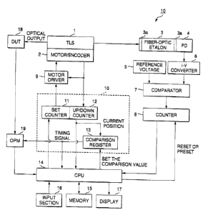
Fig. 1 is a block diagram showing the configuration of
wavelength measurement apparatus 10 according to the first
embodiment.
Fig. 2 shows the transmission characteristics of
fiber-optic Etalon.
Fig. 3 is a schematic table in time series by
synchronization signal of the set wavelength in the tunable
- 19 -
' f CA 02371988 2002-04-11
light source 1, count value of the up/down counter 12, count
value of the counter 8, and the wavelength calculated by the
CPU 14 in the wavelength measurement apparatus 10.
Fig. 4 is a block diagram showing the configuration of
wavelength measurement apparatus 20 according to the second
embodiment.
Fig. 5 is a block diagram showing the configuration of
wavelength measurement apparatus 30 according to the third
embodiment.
Fig. 6 is a schematic table in time series by
synchronization signal of the comparison value of the comparison
register 13 (value of the counter 8) , count value of the up/down
counter 12, wavelength value calculated based on the count value
of the up/down counter 12, and the actual wavelength of the
light under measurementin the wavelength measurement apparatus
30.
Fig. 7 is a block diagram showing the configuration of
a wavelength measurement apparatus 110 according to the fourth
embodiment.
Fig. 8 shows the transmission characteristics of
fiber-optic Etalon 108.
Fig. 9 is a block diagram showing the configuration of
a wavelength measurement apparatus 20 according to the fifth
embodiment.
Fig. 10 is a block diagram showing the configuration of
- 20 -
y CA 02371988 2002-04-11
a wavelength measurement apparatus 30 according to the sixth
embodiment.
Fig. 11 shows a known Michelson interferometer.
Fig. 12 is a schematic view for explaining the principle
of the known Michelson interferometer.
DETAILED DESCRIPTION OF THE PRESENT INVENTTON
The present invention will be described with reference
to the accompanying drawings.
First embodiment
Fig. 1 is a block diagram showing wavelength measurement
apparatus according to the first embodiment. The wavelength
measurement apparatus 10 comprises a tunable light source (TLS)
1, a motor/encoder 2, fiber-optic Etalon 3, a photodiode (PD)
4, a reference voltage source 5, a current-to-voltage converter
(I-V converter) 6, a comparator (COMPARATOR) 7, a counter
(COUNTER) 8, amotor driver 9, amotor controller 10, a set counter
(SETCOUNTER) 11, an up/down counter (UP/DOWN COUNTER) 12, a
comparison register 13, a CPU 14, a memory 15, an input section
16, a display (DISPLAY) 17, and an OPM 19. A DUT (Device Under
Test) 18 is shown as a target of measurement.
The tunable light source has a semiconductor laser (LD:
Laser Diode) with a non-reflective film supplied on one end,
and a tunable structure composed of a diffraction grating and
- 21 -
~ CA 02371988 2002-04-11
mirrors for adjusting the ~scillatiori of the semiconductor laser .
The tunable light source 1 is calibrated in advance so that
the oscillation wavelength may coincide with a reference
wavelength (for example 1500.000 nm) in case the reference
wavelength (1500.000 nm) is set at the input section 16.
The motor/encoder 2 comprises an encoder 2a and a motor
2b. The encoder 2a generates a signal that corresponds to the
travel amount when the position of the motor 2b has changed
and outputs the signal to the motor controller 10, which controls
the position of the motor. That is, the motor controller varies
or sweeps the oscillation wavelength of the semiconductor laser
by changing the position of the diffraction grating or mirrors
attached to the motor 2b in the tunable structure of the tunable
light source 1.
The fiber-optic Etalon 3 comprises an optical fiber and
a pair of high-reflection films (AR coating) 3a, 3b provided
perpendicular to the propagation direction of the optical fiber
on both ends of the optical fiber. The fiber-optic Etalon 3
selectively transmits only the light under measurement having
a specific wavelength determined by the physical
characteristics of the fiber-optic Etalon 3.
The photodiode 4 detects transmitted light of the
fiber-optic Etalon 3 and outputs a current according to the
intensity (power) of the transmitted light. The reference
voltage source 5 applies a specific voltage (hereinafter
- 22 -
r CA 02371988 2002-04-11
referred to as the "counter threshold voltage" ) to the comparator
7. The current-to-voltage converter6convertsa current output
from the photodiode 4 to a voltage (hereinafter referred to
as the "output voltage" ) corresponding to the magnitude of the
current, and applies the resulting voltage to the comparator
7.
The comparator 7 compares the output voltage applied by
the current-to-voltage converter 6 with the counter threshold
voltage applied by the reference voltage source and outputs
the comparison results to the counter 8. Here, action of the
comparator 7 is specifically described referring to the monitor
example of the output voltage in Fig. 2 . Tn Fig. 2, the horizontal
axis represents the wavelength of the light under measurement
and the vertical axis a voltage. The broken line represents
a counter threshold voltage.
The fiber-optic Etalon 3 selectively transmits only the
light under measurement having a specific wavelength. In case
the wavelength of the light under measurement incident on the
fiber-optic Etalon 3 is continuously swept, a cyclic peak
wave form appears on the output voltage as shown in Fig. 2. The
wavelength representing the interval between adjacent peak
waveforms (hereinafter referred to as the "peak interval
wavelength") differs depending on the physicalcharacteristics
of the fiber-opticEtalon 3. It is assumed that the peak interval
wavelength of the fiber-optic Etalon 3 is calibrated in units
- 23 -
CA 02371988 2002-02-15
of 1 pm.
The comparator 7 compares the output voltage with the
counter threshold voltage and outputs a first state siqnal as
comparison results to the counter in case the output voltage
is above the counter threshold voltage value. The comparator
7 outputs a second state signal as comparison results to the
counter in case the output voltage is below the counter threshold
~roltage value
The counter 8 increments oz' decrements the count value
each time the comparison results from the comparator 7 make
transition from the first state signal to the second state signal,
or from the second state signal to the first signal, that is,
each time the output voltage exceeds/drvps below the counter
threshold voltage value. In this way, the number of peaks of
the output voltage is counted.
The motor driver 9 references the number of pulses as
the final destination set to the set counter and applies a power
corresponding to the number of pulses to the motor 2b to make
direct drive control of the motor 2b. The motor controller
comprises the set counter 11, the up/down counter 12, and
the comparison register 13.
The set counter I1 stores the number of pulses as operation
amount of the motor 2b set by the CPU 14 in advance. The up/down
counter 12 increments the count value each time the motor 2b
is driven by one step in accordance with the response signal
- 24
CA 02371988 2002-02-15
from the motor/encoder 2 in the process of sweeping the light
under measurement as well as outputs the count value to the
controller 14 and the comparison register 13. The count value
of the up/down counter represents the current position of the
motor 2b.
The comparison register 13 stores the comparison value
updated as required by the cozztroller 14 as well as compares
the comparison value with the count value of the up/down counter
12 . In case these values match with each other, the comparison
register 13 outputs a synchronization signal (TIMINGSIGNAL)
to the CPU 14 and the OPM 17.
The CPU 14 performs centralized control of the components
and calculates in zeal time the wavelength of the Light under
measurement based on the current count value of the counter
8 and the reference wavelength value (for example 1500. 000 [nm]
stored in the memory 15. The memory 15 comprises an EEQROM
(Electrically Erasable, Programmable Read Only Memory) and
flash ROM and stores the first table that specifies the
relationship between the number of pulses and wavelength of
the motor 2b and the reference wavelength.
The input sect~.on 16 is equipped with various keys for
the opexator to input a desired reference wavelength. The
display 17 displays in real time the wavelength of the light
under measurement calculated by the CPU 14. The DUT 18 is a
target of measurement by an optical module, optical splitter
- 25 -
CA 02371988 2002-04-11
and optical circulator. On the DUT 18 are incident laser beams
from the tunable light source 1. The OPM 19 detects the
transmitted light of the DUT 18 and outputs the intensity of
the detected transmitted light to the CPU 14.
Operation of the wavelength measurement apparatus 10 in
Fig. 1 will be described below. The operator sets the reference
wavelength (for example 1500.000 [nm] ) in advance at the input
section 16. Then the reference light calibrated so as to
precisely coincide with the reference wavelength is emitted
to the fiber-optic Etalon 3 from the tunable light source 1.
The CPU 14, detecting that the reference light has been incident
on the fiber-optic Etalon 3, resets (or presets ) the count values
of the counter 8 and the up/down counter 12 and sets each count
value to zero.
Next, the CPU 14, detecting that the reference wavelength
is input, stores the input reference wavelength (1500.000 [nm] )
into the memory 15.
Then, the operator enters the final wavelength obtained
at completion of the sweep process at the input section 16. ,
Detecting the input of the final wavelength, the CPU 14
references the memory 15 to recognize the number of pulses as
the final destination of the motor 2b corresponding to the final
wavelength, and sets the number of pulses recognized as the
final destination to the set counter 11. When the number of
pulses is set to the set counter 11, The motor driver 9 starts
- 26 -
' t CA 02371988 2002-04-11
driving the motor/encoder 2 thus starting the wavelength sweep
of the light under measurement. In the process, the encoder
2a outputs a response signal to the motor driver 9 and the up/down
counter 12 each time the motor 2b is driven by one step.
The up/down counter 12 increments the count value each
time it detects a response signal from the motor/encoder 2,
and outputs the incremented count value to the comparison
register 13 and the CPU 14. The comparison register l3 outputs
a synchronization signal to the CPU 14 and the OPM 19 each time
the comparison value stored in the comparison register 13
coincides with the count value of the up/down counter 13.
The CPU 14 reads the count value of the counter 8 each
time it detects a synchronization signal. The CPU 14 then
calculates the sum of the relative variation of the wavelength
obtained by multiplying the read count value by the peak interval
wavelength (for example 1 [pm]) and the reference wavelength
(1500.00 [nm]) stored in the memory 15 in advance. The OPM
19 captures the optical output from the DUT 18 and transfers
the optical output captured to the CPU 14. .
Then, the CPU 14 instructs the display to monitor in real
time the wavelength of the light under measurement calculated
and the optical output from the OPM 19 as well as updates the
comparison value of the comparison register 13 to next value.
In this way, the local wavelength at that point in time is
monitored each time a synchronization signal is issued. Fig.
- 27 -
CA 02371988 2002-04-11
3 is a schematic representation in time series by synchroni zation
signal of the set wavelength in the tunable light source 1,
count value of the up/down counter 12, count value of the counter
8, and the wavelength calculated by the CPU 14 . Fig: 3 assumes
that the comparison value of the comparison register is updated
in intervals of 10 seconds, such as 10, 20, 30, . . , by the CPU
14.
According to the wavelength measurement apparatus 10 of
the embodiment, the following advantages are obtained:
(1) The count value (number of peaks) currently counted
by the counter 8 represents a relative variation in the
wavelength from the start of sweep to this point in time . The
CPU 14 calculates in real time the wavelength of the light under
measurement based on the count value byusing the synchroni zati:on
signal as a trigger, so that the CPU 14 can monitor the
instantaneous wavelength value of the light under measurement
at this point in time. As a result, it is possible to measure
the wavelength of the light under measurement under sweep process
with high accuracy and in real time even in case the wavelength
is continuously swept.
(2) The shorter the wavelength interval, the better the
resolution of wavelength variation during sweep. For the
fiber-optic Etalon 3, it is possible to provide the sufficient
length so that it is easy to measure the wavelength of
continuously swept light under measurement with accuracies of
- 28 -
'- CA 02371988 2002-04-11
for example 1 pm to 0.1 pm or better.
(3) The comparison register 12 outputs a synchronization
signal each time the motor 2b is driven by predetermined number
of pulses. The CPU 14 reads the count value of the counter
8 as correction data each time the synchronization signal is
output and calculates the wavelength. It is thus possible to
automatically calculate and monitor in sequence the wavelength
of the light under measurement in the process of sweeping the
wavelength of the light under measurement.
Description of the first embodiment is a preferred example
of wavelength measurement apparatus 10 according to the
invention and the invention is not limited to this embodiment.
For example, a heat insulator is preferably provided that keeps
constant the, embodiment temperature of the fiber-optic Etalon
3 within ~0.1 qC to ~0.01 'C or better stability. Such a heat
insulator can comprise for example a thermistor or a Peltier
cooling element. In case the wavelength measurement apparatus
is composed in this way, accuracy of the measured value is
guaranteed in a better order. .
It is demonstrated that the finesse (wavelength interval)
of the fiber-optic Etalon 3 varies with the wavelength of light
undermeasurement and the finesse gets narrower as the wavelength
becomes longer. This variation in the finesses is on the order
of 5/100 pm with respect to a variation in the wavelength of
1 nm and thus sufficiently negligible . In case the wavelength
- 29 -
' CA 02371988 2002-04-11
is swept over a wide range, the finesse is preferably calibrated
as required based on a theoretical formulae such as the Airy's
formulae or a measured value.
In case the wavelength interval of the fiber-optic Etalon
cannot be keyed to an accurate value due to disturbance such
as a temperature, it is possible to correct the wavelength based
on the initial wavelength (WLS) at start of sweep and the final
wavelength (WLE) at completion of sweep. Assuming that the
accuracies of WLS and WLE at wavelength halt are respectively
'!- d WL, the maximum wavelength sweep interval ( 0 WLmax) is
represented by the following expression (3):
d WLmax= (WLE-WLS ) +2 D WL ( 3 )
The minimum wavelewgth sweep interval ( 0 WLmin) is
represented by the following expression (4):
d WLmin= (WLE-WLS 7 -2 ~ WL ( 4 )
Assuming that the number of peaks obtained during sweep
of the wavelength is N, the wavelength interval at a single
count is ~WLmax/N or~WLmin/N. Thus, the difference between
the two is the error (EWL) in the wavelength interval during
wavelength sweep. That is,
- 30 -
~
CA 02371988 2002-04-11
EWL= 0 WLmax/N- ~ WLmin/N ( 5 )
Assuming that the interval of adjacent peaks is set to
1 [pm] , sweeping the light under measurement over 1 [nm] results
in the final count value N of the counter being 1000. Thus,
assuming that OWL=15 [pm] , EWL is 0. 06 [pm] . AWL=0 is allowed
by measuring WLS using a wavemeter whose accuracy is guaranteed
to be sufficiently high in wavelength sweep as well as checking
WLE on the wavemeter at completion of the sweep. Thus the error
EWL can be reduced to 0. It is clear that using either WLS
or WLE can reduce the error.
The value of the length of the light under measurement
in the interval between synchronization signals maybe estimated
through interpolation using a known interpolation method such
as the least square method. Further, the motor 2b may be in
particular composed of a DC servo motor, AC servo motor, or
a pulse motor that does not use an encoder. Employing any type
of such a motor allows control similar to the aforementioned
control. Detailed configuration and operation of the
wavelength measurement apparatus 10 can be changed as required
without departing from the range of the invention.
Second embodiment
Fig. 4 is a block diagram showing the configuration of
wavelength measurement apparatus 20 according to the second
- 31 -
' ' CA 02371988 2002-04-11
embodiment of the invention. In Fig. 4, same components as
those of the aforementioned wavelength measurement apparatus
are given the same signs and corresponding description is
omitted. The wavelength measurement apparatus 20 is
characterized of comprising a photocoupler 21, a photodiode
22, and a reference voltage source 23.
The photocoupler 21 branches the outgoing light of the
tunable light source 1 to light under measurement to be incident
on the fiber-optic Etalon 3 and reference light to be incident
on the photodiode 22 before the fiber-optic Etalon 3. The
photodiode 22 outputs a current corresponding to the reference
light branched by the photocoupler 21. The reference voltage
source 23 applies the reference voltage (counter threshold
voltage) corresponding to the current value output from the
photodiode 22 to the subsequent comparator 7.
According to the wavelength measurement apparatus 20,
the reference voltage (counter threshold voltage) applied to
the comparator 7 varies with the light intensity of the outgoing
light of the tunable light source 1. Even in case the intensity
of the outgoing light of the tunable light source 1 is subj ect
to fluctuation, it is possible to avoid an error in the count
value of the counter 8 caused by the fluctuation. That is,
the fluctuation exerts an influence on both the output voltage
of I-V converter and the reference voltage (counter threshold
voltage) from the reference voltage source so that the
- 32 -
' CA 02371988 2002-04-11
fluctuation is canceled when the comparator 7 compares these
values with each other.
Third embodiment
Fig. 5 is a block diagram showing the configuration of
wavelength measurement apparatus 30 according to the third
embodiment of the invention. In Fig. 5, same components as
those of the aforementioned wavelength measurement apparatus
20 are given the same signs and corresponding description is
omitted. The wavelength measurement apparatus30is configured
generally the same as the wavelength measurement apparatus 20
according to the second embodiment but is characterized of
determining the timing to issue a synchronization signal based
on the value of the counter 8.
The memory 15 stores the third table that specifies the
variation in the wavelength of light under measuremen per unit
count value of the upldown counter 12.
Operation of the wavelength measurement apparatus 30 will
be described below. The operator sets the sweep start
wavelength (WLS) (for example 1499.990 [nm~ ) in advance at the
input section .16. Then the sweep start wavelength (WLS) is
stored into the memory l5 by the CPU 14 and the light under
measurement calibrated so as to precisely coincide with the
sweep startwavelength (WLS) is emitted to the fiber-opticEtalon
3 from the tunable light source 1. The CPU 14, detecting that
- 33 -
' CA 02371988 2002-04-11
the light under measurement has been incident on the fiber-optic
Etalon 3, resets (or presets) the count values of the counter
8 and the up/down counter 12 and sets each count value to zero.
Then, the operator enters the final wavelength obtained
at completion of the sweep process at the input section 16.
Detecting the input of the final wavelength, the CPU 14
references the memory 15 to recognize the number of pulses as
the final destination of the motor 2b corresponding to the final
wavelength, and sets the number of pulses recognized as the
final destination to the set counter 11. The CPU 14 further
sets the initial value of the comparator value to the comparison
register 13.
When the number of pulses is set to the set counter 11,
The motor driver 9 starts driving the motor/encoder 2 thus
starting the wavelength sweep of the light under measurement .
In the process, the encoder 2a outputs a response signal to
the motor driver 9 and the up/down counter 12 each time the
motor 2b is driven by one step. Theup/down counter 12 increments
the count value each time.it detects a response signal, and
outputs the incremented count value to the CPU 14. The CPU
14 recognizes the current position of the motor 2b based on
the count value of the up/down counter 12.
In the process the wavelength is swept, the count value
of the counter 8 is referenced by the comparison register 13
as required, and in case the count value of the counter 8 has
- 34 -
' ' CA 02371988 2002-04-11
matched the comparison value, a synchronization signal
(TIMINGSIGNAL) is output from the comparison register 13 to
the CPU 14 and the OPM 19.
The CPU 14, each time it detects a synchronization signal,
reads the count value of the up/down counter 12 as correction
data and calculates the length of the light under measurement
based on the read count value and the third table of the memory
15. The OPM 19, each time it detects a synchronization signal,
captures the optical output from the DUT 18 and transfers the
captured optical output to the CPU 14.
Then, the CPU 14 instructs the display to monitor in real
time the wavelength of the light under measurement calculated
and the optical output from the OPM 19 as well as sequentially
updates the comparison value of the comparison register 13 to
next value . In this way, the local wavelength at that point
in time is monitored each time a synchronization signal is issued.
Fig. 6 is a schematic representation in time series by
synchronization signal of the comparison value of the comparison
register 13 (value of the counter 8) , count value of the up/down '
counter 12, wavelength value calculated based on the count value
of the up/down counter 12, and the actual wavelength of the
light under measurement. In the figure, the peak interval of
the transmitted~light of the fiber-optic Etalon 3 is calibrated
in units of pm/count and the sweep start wavelength (WLS) is
known so that the comparison value of the comparison register
- 35 -
' ' CA 02371988 2002-04-11
12 and the actual wavelength of the light under measurement
are in one-to-one correspondence. Fig. 6 assumes that the
comparison value of the comparison register is updated in
intervals of 10 peaks.
In case the comparison value is not calibrated nor the
sweep start wavelength is known, it is preferable that the count
value of the up/down counter 12 is referenced when a
synchronizationsignal is issued and the wavelength is corrected
in accordance with the expressions (3) through (5).
FOURTH EMBODIMENT
Fig. 7 is a block diagram showing a wavelength measurement
apparatus according to the fourth embodiment. The wavelength
measurement apparatus 110 comprises a tunable light source (TLS)
101, a motor/encoder 102, photocouplers 103, 107, a gas cell
104, photodiodes 105, 109, 111, current-to-voltage converters
106, 110, fiber-optic Etalon 108, a reference voltage source
112, a comparator 113, a counter 114, a motor driver 115, a
first comparison register 117, a second comparison register
118, a CPU 119, an input section 120, a memory 121, a display
122, and an OPM 124. A DUT (Device Under Test) 123 is shown
as a target of measurement.
While not shown, the tunable light source has a
semiconductor laser (LD: Laser Diode) with a non-reflective
film supplied on one end, and a tunable structure composed of
- 36 -
' ~ CA 02371988 2002-04-11
a diffraction grating and mirrors for adjusting the oscillation
of the semiconductor laser. The tunable light source 101 is
calibrated in advance so that the oscillation wavelength may
coincide with a reference wavelength (for example 1500 . 000 nm)
in case the reference wavelength (1500.000 nm) is set at the
input section 120.
The motor/encoder 102 comprises an encoder 102a and a
motor 102b. The encoder 102a outputs a pulse signal
corresponding to the rotation speed of the rotation shaft in
the motor 102b to the motor controller 116 . The motor controller
116 calculates the number of pulses of a pulse signal input
from the encoder 202a and controls the rotation speed of the
rotation shaft in the motor 102b based on the set count value
input from the CPU 119. That is, by changing the position of
the diffraction grating or mirrors attached to the motor/encoder
102 constituting the tunable structure of the tunable light
source 101, oscillation wavelength of the semiconductor laser
is continuously varied for sweep process.
The photocoupler 103 branches the light under measurement
incident from the tunable light source 101 to a light beam to
be incident on the gas cell 104 and a light beam to be incident
on the photocoupler.
The gas cell 104 is a glass cell containing 12-acetylene
gas or 13-acetylene gas as an isotope thereof or cyanide gas
inside the glass cell: The gas cell 104 intensely absorbs the
37 -
' ' CA 02371988 2002-04-11
light under measurement only in case the wavelength of branched
by the photocoupler 103 and incident has reached the wavelength
of the absorption line of the gas (hereinafter referred to as
"absorption wavelength").
The photodiode 105 detects the transmitted light of the
gas cell 104 and outputs a current corresponding to the intensity
(power) of. the transmitted light. The current-to-voltage
converter 146 converts a current output from the photodiode
105 to a voltage corresponding to the magnitude of the current,
and applies the resulting voltage to the CPU 119.
The photocoupler 107 further branches the light under
measurement branched by the photocoupler 103 to light incident
on the fiber-optic Etalon 108 and light incident on the
photodiodelll. The fiber-optic Etalon108comprisesan optical
fiber and a pair of high-reflection films (AR coating) 108a,
108b provided perpendicular to the propagation direction of
the optical fiber on both ends of the optical fiber. The
fiber-optic Etalon 108 has a free spectral range (FSR) shorter
than the interval between any two types of absorption wavelengths
of the gas cell 104.
The photodiode 109 detects transmitted light of the
fiber-optic Etalon 108 and outputs a current according to the
intensity (power) of the transmitted light: The
current-to-voltage converter 110 converts a current output from
the photodiode 109 to a voltage (hereinafter referred to as
- 38 -
' CA 02371988 2002-04-11
the "output voltage") corresponding to the magnitude of the
current, and outputs the resulting voltage to the comparator
113.
The photodiode 111 detects light under measurement
branched by the photocoupler 107 and outputs a current according
to the intensity (power) of the transmitted light. The
reference voltage source 112 outputs a reference voltage
(counter threshold voltage) corresponding to the current value
output from the photodiode 111 to the comparator 113.
The comparator 113 compares the output voltage output
from the current-to-voltage converter 110 with the counter
threshold voltage output from the reference voltage source and
outputs the comparison results to the counter 11~. Here,
operation of the cornparator 113 is specifically described
referring to the monitor example of the output voltage in Fig.
8. In Fig. 8, the horizontal axis represents the wavelength
of the light under measurement and the vertical axis an output
voltage value. The broken line represents a counter threshold
voltage . While the counter threshold voltage is constant in ,
Fig. 8, the counter threshold voltage actually varies with the
light intensity of the emitted light of the tunable light source
101.
The fiber-optic Etalon 108 selectively transmits only
the light under measurement having a specific wavelength. In
ease the wavelength of the light under measurement incident
39 _
o a
CA 02371988 2002-04-11
on the fiber-optic Etalon 108 is continuously swept, a cyclic
peak waveform appears on the output voltage as shown in Fig.
8. The wavelength representing the interval between adjacent
peak waveforms (FSR) depends on the physical characteristics
of the fiber-optic Etalon 108: It is assumed that the FSR of
the fiber-optic Etalon 1f8 is calibrated in units of 1 pm.
The comparator 113 compares the output voltage with the
counter threshold voltage and outputs a first state signal as
comparison results to the counter 114 in case the output voltage
is above the counter threshold voltage value. The comparator
113 outputs a second state signal as comparison results to the
counter 114 in case the output voltage is below the counter
threshold voltage value.
The counter 114 increments or decrements the count value
each time the comparison results input from the comparator 113
make transition from the first state signal to the second state
signal, or from the second state signal to the first signal,
that is, each time the output voltage exceedsldrops below the
counter threshold voltage value.
The motor driver 115 uses the CPU 119 to adjust the
application time of the motor drive signal applied to the motor
102b based on the count value set to the set counter 161 in
the motor controller 116 thereby controlling the rotation speed '
of the rotation shaft in the motor 102b.
The motor controller 116 comprises a set counter 161 and
- 40 -
CA 02371988 2002-04-11
an up/down counter 162 . The set counter 161 is a counter where
the count value corresponding to the rotation speed of the
rotation shaft in the motor 102b is set by the CPU 119. The
up/down counter162 increments/decrements the number of pulses
of a pulse signal input from the encoder 102a in the process
of sweeping light under measurement and outputs the count value
obtained to the CPU 119, the first comparison register 117,
and the second comparison register 118. The count value of
the up/down counter 162 represents the rotation speed of the
rotation shaft in the motor 102b.
The first comparison register 117 stores the comparison
value updated and input as required by the CPU 119 as well as
compares the comparison value with the count value input from
the up/down counter 162 . In case the comparison results match
with each other, the first comparison register 117 outputs a
synchronization signal (TIMINGSIGNAL) to the CPU 119 and the
OPM 124.
The second comparison register 118 stores the comparison
value updated and input as required by the CPU 119 as well as
compares the comparison value with the count value input from
the up/down counter 162 . In case the comparison results match
with each other, the first comparison register 117 outputs a
synchronization signal (TIMINGSIGNAL) to the CPU 119.
The CPU 119 acquires the count value of the counter 114
each time it detects a synchronization signal input from the
- 41 -
r CA 02371988 2002-04-11
first comparison register 117 as well as acquires the voltage
value input as a signal for correcting the wavelength value
from the current-to-voltage converter 106 each time it detects
a synchronization signal input from the second comparison
register 118. The CPU 119 calculates the wavelength of the
light under measurement based on these values.
The input section 120 is equipped with various keys for
the operator to input a desired reference wavelength. The
memory 121 comprises an EEPROM (Electrically Erasable,
Programmable Read Only Memory) and flash ROM and stores the
first table that specifies the relationship between the number
of pulses and wavelength of the motor 102b and the second table
that specifies the wavelength absorption position of a
pre-calibrated gas cell. The display 122 displays the
wavelength of the light under measurement calculated by the
CPU 119.
The DUT 123 is a target of measurement by an optical module,
optical splitter and optical circulator. On the DUT 123 are
incident laser beams from the tunable light source 101. The
OPM 124 detects the transmitted light of the DUT 123 and outputs
a signal corresponding to the intensity of the detected
transmitted light to the CPU 119.
Operation of~the.wavelength measurement apparatus 110
in Fig. 7 will be described below.
The operator sets the reference wavelength ( for example
- 92 -
CA 02371988 2002-04-11
1500.000 [nm]) in advance at the input section 120. The CPU
119 sets the count value corresponding to the input reference
wave form to the set counter 161. The motor driver 115; based
on the count value set to the set counter 161, adjusts the
application time of the motor drive signal to be applied to
the motor 102b and controls the rotation speed of the motor
102b so that the tuning mechanism in the tunable light source
may radiate light with the reference wavelength.
Next, the CPU 119 stores the reference wavelength
(1500. 000 [nm] ) input from the input section 120 into the memory
121 as well as resets the count values of the counter 114 and
the up/down counter 162 and sets each count value to zero.
Then, the operator enters the final wavelength obtained
at completion of the sweep process at the input section 120.
The CPU 119 references the first table in the memory 121 to
recognize the number of pulses (count value) as the final
destination of the motor 102b corresponding to the final
wavelength, and sets the count value recognized to the set
counter 161. The motor driver 115, based on the count value ,
set to the set counter 161 by the CPU 119, adjusts the application
time of the motor drive signal to be applied to the motor 102b
and controls the rotation speed of the rotation shaft in the
motor 102b.
The up/down counter 162 increments the count value each
time it detects a pulse signal input from the encoder 2, and
- 43 -
' CA 02371988 2002-04-11
outputs the incremented count value to the first comparison
register 13, the second comparison register 118 and the CPU
119. The first comparison register 117 outputs a
synchronization signal to the CPU 119 and the OPM 124 each time
the comparison value stored by the CPU 119 coincides with the
count value of the up/down counter 162.
The CPU 119 reads the count value of the counter 114 each
time it detects a synchronization signal input from the first
comparison register 117. The CPU 119 then calculates the sum
of the relative variation of the wavelength obtained by
multiplying the read count value by the peak interval wavelength
(initial value is for example 1 [pm]) and the reference
wavelength (1500.00 [nm] ) stored in the memory 15 in advance.
By doing so, the CPU 119 obtains the current wavelength value
of the light under measurement.
The wavelength value of the light under measurement is
corrected based on the absorption wavelength position of the
gas cell 104. The CPU 119 acquires the voltage value input
as a signal for correcting the wavelength value from the
current-to-voltage converter 106 each time it detects a
synchronization signal input from the second comparison
register 118.
In case the CPU 119 has read wavelength absorption
positions on at least two points, the CPU 119 divides the interval
between the wavelength absorption positions (wavelengthscale)
- 44 -
CA 02371988 2002-04-11
by the count value counted by the counter 114 to correct the
peak interval wavelength value (FSR) of the fiber-optic Etalon
108,
Each time a synchronization signal is input from the first
comparison register or second comparison register, the CPU 119
updates the comparison value set to each of the registers as
required. The OPM 124 outputs to the CPU 119 a signal
corresponding to the light output intensity of the transmitted
light received from the DUT 123 each time it detects a
synchronization signalinput from the first comparison register
117 . Then the CPU 119 uses the peak interval wavelength ( FSR)
of the fiber-optic Etalon 108 corrected to correct the wavelength
of a synchronization signal generated by the first comparison
register, thus making the display 122 to display the wavelength
of the corrected light under measurement and optical output
corresponding to the intensity of the transmitted light of the
DUT 123 input from the OPM 124.
According to the wavelength measurement apparatus 110
of the embodiment, the following advantages are obtained:
(1) It is possible to determine the wavelength of light
under measurement based on a plurality of wavelength absorption
positions of the pre-calibrated gas cell 104. Accordingly,
the CPU 119 can calculate the wavelength value of the light
under measurement with high accuracy.
(2) The CPU 119 divides the interval between two types
- 45 -
CA 02371988 2002-04-11
of wavelength absorption positions by the count value counted
by the counter 114 while the wavelength of the light under
measurement makes transition from one of the two types of
wavelengths to the other thereby correcting the FSR of the
fiber-optic Etalon 108. This assures high-accuracy
measurement of the wavelength of the light under measurement.
In case the wavelength of the light under measurement varies
between absorption wavelengths at two points of the gas cell
104 and FSR of the fiber-optic Etalon 108 is once corrected,
the wavelengths outside the two types of wavelengths can be
corrected in real time by retaining the corrected value.
(3) The count value (number of peaks) currently counted
by the counter 114 represents a relative variation in the
wavelength from the start of sweep to this point in time . The
CPU 119 calculates in real time the wavelength of the light
under measurement based on the count value by using the
synchronization signal as a trigger, so that the CPU 119 can
monitor the instantaneous wavelength value of the light under
measurement at this point in time. As a result, it is possible
to measure the wavelength of the light under measurement under
sweep process with high accuracy even in case the wavelength
is continuously swept.
( 4 ) The shorter the FSR interval, the better the resolution
of wavelength variation during sweep. For the fiber-optic
Etalon 108, it is possible to provide the sufficient length
- 46 -
' CA 02371988 2002-04-11
so that it is easy to measure the wavelength of continuously
swept light under measurement with accuracies of for example
1 (pm] or better.
(5) The reference voltage (counter threshold voltage)
applied to the comparator 113 varies with the light intensity
of the outgoing light of the tunable light source 101: Even
in case the intensity of the outgoing light of the tunable light
source 101 is subject to fluctuation, it is possible to avoid
an error in the count value of the counter 114 caused by the
fluctuation. That is, the fluctuation exerts an influence on
both the output voltage of current-to-voltage converter and
the reference voltage (counter threshold voltage) from the
reference voltage source so that the fluctuation is canceled
when the comparator 113 compares these values with each other.
Description of the fourth embodiment is a preferred
example of wavelength measurement apparatus 110 according to
the invention and the invention is not limited to this embodiment .
For example; the gas cell 104 is employed to mark wavelength
values on at least two points within the wavelength variation
range, Fabry-Perot Etalon, an interference optical filter, or
a band-pass filter with the cycle of the free spectral range
(FSR) pre-calibrated accurately may be employed instead of the
gas cell 104.
A heat insulator is preferably provided that keeps
constant the embodiment temperature of the fiber-optic Etalon
- 47 -
' CA 02371988 2002-04-11
108 within ~0 .1 ~C to '~ 0 . 0l °C or better stability. Such a heat
insulator can be composed of for example a thermistor or a Peltier
cooling element. In case the wavelength measurement apparatus
is composed in this way, expansion/contraction of the length
L of the fiber-optic Etalon and a change in the refraction index
n can be prevented so that accuracy of the measured value is
guaranteed in a better order.
In case the wavelength interval of the fiber-optic Etalon
cannot be keyed to an accurate value due to disturbance such
as a temperature, it is possible to correct the wavelength based
on the initial wavelength (WLS) at start of sweep and the final
wavelength (WLE) at completion of sweep. Assuming that the
accuracies of WLS and WLE at wavelength halt are respectively
~ ~ WL, the maximum wavelength sweep interval ( ~ WLmax) is
represented by the following expression (3):
~ WLmax= (WLE-WLS ) -r2 ~ WL ( 3 )
The minimum wavelength sweep interval (tlWLmin) is
represented by the following expression (4):
~ WLmin= (WLE-WLS) -2 L1 WL ( 4 )
Assuming that the number of peaks obtained during sweep
of the wavelength is N, the wavelength interval at a single
- 48 -
' ' CA 02371988 2002-04-11
count is OWLmax/N or~WLminlN. Thus, the difference between
the two is the error (EWL) in the wavelength interval during
wavelength sweep. That is,
EWL= ~ WLmax/N- D WLmin/N ( 5 )
Assuming that the interval of adjacent peaks is set to
1 [pm] , sweeping the light under measurement over 1 [nm] results
in the final count value N of the counter being 1000. Thus,
assuming that AWL=15 [pm] , EWL is 0. 06 [pm] . OWL=0 is allowed
by measuring WLS using a wavemeter whose accuracy is guaranteed
to be sufficiently high in wavelength sweep as well as checking
WLE on the wavemeter at completion of the sweep. Thus the error
EWL can be reduced to 0. It is clear that using either WLS
or WLE can reduce the error.
It is demonstrated that the FSR of the fiber-optic Etalon
108 varies with the wavelength of light under measurement and
the finesse gets narrower as the wavelength becomes longer.
This variation in the finesses is on the order of 5/100 pm with
respect to a variation in the wavelength of 1 nm and thus
sufficiently negligible. In case the wavelength is swept over
a wide range, the finesse is preferably calibrated as required
based on a theoretical formulae such as the Airy's formulae
or a measured value.
The value of the length of the light under measurement
- 49 -
' CA 02371988 2002-04-11
in the interval between synchronization signals maybe estimated
through interpolation using a known interpolation method such
as the least square method. Further, the motor 102b may be
in particular composed of a DC servo motor, AC servo motor,
or a pulse motor. Employing any type of such a motor allows
control similar to the aforementioned control. Detailed
configuration and operation of the wavelength measurement
apparatus 110 can be changed as required without departing from
the range of the invention.
FIFTH EMBODIMENT
Fig. 9 is a block diagram showing the configuration of
wavelength measurement apparatus 120 according to the fifth
embodiment of the invention. In Fig. 9, same components as
those of the aforementioned wavelength measurement apparatus
110 are given the same signs and corresponding description is
omitted. The wavelength measurement apparatus 120 is
configured generally the same as the wavelength measurement
apparatus 310 according to the fourth embodiment but is
characterized of determining the timing to issue the
synchronization signals of the first comparison register 117
and the second comparison register 118 based on the count value
of the counter 114.
In the wavelength measurement apparatus 120, the memory
121 stores the third table that specifies the variation in the
- 50 -
' r CA 02371988 2002-04-11
wavelength of light under measurement per unit count value of
the up/down counter 162.
Operation of the wavelength measurement apparatus 120
will be described below.
The operator sets the reference wavelength ( for example
1500.000 [nm]) in advance at the input section 120. The CPU
119 sets the count value corresponding to the input reference
wave form to the set counter 161. The motor driver 115, based
on the count value set to the set counter 161, adjusts the
application time of the motor drive signal to be applied to
the motor 102b and controls the rotation speed of the motor
102b so that the tuning mechanism in the tunable light source
may radiate light with the reference wavelength. The reference
light calibrated to coincide with the preset reference
wavelength is emitted accurately from the tunable light source
101 to the gas cell 104 and the fiber-optic Etalon 108.
Next, the CPU 119 stores the reference wavelength
(1500. 000 [nm] ) input from the input section 120 into the memory
121 as well as resets the count values of the counter 114 and
the up/down counter 162 and sets each count value to zero.
Then, the operator enters the final wavelength obtained
at completion of the sweep process at the input section 120.
The CPU 119 references the first table in the memory 121 to
recognize the number of pulses (count value) as the final
destination of, the motor 102b corresponding to the final
- 51 -
CA 02371988 2002-04-11
wavelength, and sets the count value recognized to the set
counter 161. The motor driver 115, based on the count value
set to the set counter 161 by the CPU 119, adjusts the application
time of the motor drive signal to be applied to the motor 102b
and controls the travel amount of the driver in the motor 102b.
The up/down counter 162 increments the count value each
time it detects a pulse signal input from the encoder 102, and
outputs the incremented count value to the first comparison
register 117, the second comparison register 118 and the CPU
119. The first comparison register 117 outputs a synchronization
signal to the CPU 119 and the OPM 124 each time the comparison
value stored by the CPU 119 coincides with the count value of
the up/down counter 162.
The CPU 119 reads the count value of the counter 114 each
time it detects a synchronization signal input from the first
comparison register 117 . The CPU 119 multiplies the read count
value by the wavelength variation per unit count value specified
in the third table to calculate the variation in the wavelength
value of the light under measurement. The CPU 119 then uses
the sum of the variation and the reference wavelength at the
start of sweep to calculate the current wavelength value of
the light under measurement.
The wavelength value of the light under measurement is
corrected based on the absorption wavelength position of the
gas cell 104. The CPU 119 acquires the voltage value input
- 52 -
' CA 02371988 2002-04-11
as a signal for correcting the wavelength value from the
current-to-voltage,converter 106 each time it detects a
synchronization signal input from the second comparison
register 118.
In case the CPU 119 has read wavelength absorption
positions on at least two points, the CPU 119 divides the interval
between the wavelength absorption positions by the count value
counted by the counter 114 to correct the peak interval
wavelength value (FSR) of the fiber-optic Etalon 108.
Each time a synchronization signal is input from the first
comparison register or second comparison register, the CPU 119
updates the comparison value set to each of the registers as
required. The OPM 124 outputs to the CPU 119 a signal
corresponding to the light output intensity of the transmitted
light received from the DUT 123 each time it detects a
synchronization signalinput from the first comparison register
117. Then the CPU 119 instructs the display 122 to display
the wavelength of the light under measurement calculated and
the optical output corresponding to the transmitted light
intensity of the DUT 123 input from the OPM 124. The wavelength
measurement apparatus 120 provides the same advantage as the
aforementioned wavelength measurement apparatus 110.
SIXTH EMBODIMENT
Fig. 10 is a block diagram showing the configuration of
- 53 -
CA 02371988 2002-04-11
wavelength measurement apparatus 130 according to the sixth
embodiment of the invention. In Fig. 10, same components as
those of the aforementioned wavelength measurement apparatus
110 are given the same signs and corresponding description is
omitted. The wavelength measurement apparatus 130 is
configured generally the same as the wavelength measurement
apparatus 110 according to the fourth embodiment but is
characterized of employing Fabry-Perot Etalon 131 instead of
the gas cell 104 and comprising a comparator 132.
It is assumed that the Fabry-Perot Etalon 131 has been
pre-calibrated so that the free spectral range (FSR) may
accurately coincide with 1 [nm]. The comparator 132 compares
the counter threshold voltage from the reference voltage source
112 with the output voltage from the current-to-voltage
converter 106 and outputs the comparison results to the CPU
119.
In the wavelength measurement apparatus 130, the
wavelength of the light under measurement is corrected as
required based on the free spectral range (FSR) of the
Fabry-Perot Etalon 131. That is, the CPU 119 acquires the
comparison results as a signal for correcting the wavelength
value from the comparator 132 each time it detects a
synchronizationsignalfrom the second comparison register118.
The CPU 119 then recognizes the interval of the free spectral
range ( FSR) of the Fabry-Perot Etalon 131 based on the comparison
- 54 -
f i
CA 02371988 2002-04-11
results.
The CPU 119, detecting that the transmitted output of
the Fabry-Perot Etalon 131 has reached its peak based on the
comparison results from the comparator 132, corrects and
determines the relative travel amount of the light under
measurement based on multiples of the free spectral range (FSR)
of the Fabry-Perot Etalon 131 . The CPU 119 divides the interval
of the free spectral range (FSR) of the Fabry-Perot Etalon by
the count value counted by the counter 114 while the wavelength
of the light under measurement varies in the interval, to correct
the FSR of the fiber-optic Etalon 108. The wavelength
measurement apparatus 130 provides the same advantage as the
aforementioned wavelength measurement apparatus 110.
A counter for counting the number of peaks of the
transmitted output of the Fabry-Perot Etalon 131 and a comparison
register for outputting a synchronization signal each time the
counter value reaches a predetermined value may be provided
after the comparator 132.
According to the first or second aspect of the invention,
it is possible to measure the wavelength of light under
measurement under sweep process with high accuracy and in real
time even in case the wavelength is continuously swept.
According to the third, fourth; or fifth aspect of the
invention, it is possible to calculate in real time the
_ 55 -
' CA 02371988 2002-04-11
wavelength of light under measurement per predetermined timing
in the process of sweeping the light under measurement. It
is al so possible to calculate, correct anddisplaythewavelength
based on the count values after capturing the count values:
According to the sixth aspect of the invention; it is
made easy to accurately calculate the number of peaks of the
output of the photo-detector.
According to the seventh aspect of the invention, even
in case a fluctuation is present in the intensity of the light
under measurement, it is possible to avoid an error in the count
value caused by the fluctuation. That is, the fluctuation
exerts an influence on both the output of the photo-detector
and the reference value so that it is possible to cancel the
fluctuation in case these values are compared with each other.
According to the eighth aspect of the invention, in ease
an error is present in the calculation results of the controller,
the error can be reduced. In particular, in case the wavelength
value of the light under measurement is corrected based on both
the sweep start wavelength value and the sweep end wavelength
value, the accuracy of wavelength halt of the light under
measurement (~ AWL) at the start and end of sweep can be set
to zero. As a result, an error in the peak interval can be
set to zero . This obtains a more accurate wavelength value .
According to the ninth aspect of the invention; it is
possible to measure the wavelength of continuously swept light
- 56 -
1 Y
CA 02371988 2002-04-11
under measurement with accuracies of for example 1 pm to 0.1
pm or better.
According to the tenth aspect of the invention, it is
possible to prevent expansion/contraction of the length L of
the fiber-optic Etalon caused by variation in the ambient
temperature. This assures more accurate measurement of the
wavelength of light under measurement.
According to an eleventh through fifteenth aspects of
the invention, it is possible to measure the wavelength of the
light under measurement under sweep process with high accuracy
even in case the wavelength is continuously swept.
According to the sixteenth through eighteenth aspects
of the invention, it is possible to capture the wavelength of
the light under measurement per predetermined timing in the
process of sweeping the light under measurement. It is also
possible to calculate, correct and display the wavelength based
on the count values after capturing the count values.
According to the nineteenth aspect of the invention, it
is made easy to accurately calculate the number of peaks of
the output of the photo-detector.
According to the twentieth aspect of the invention, even
in case a fluctuation is present in the intensity of the light
under measurement, it is possible to avoid an error in the count
value caused by the fluctuation.
According to the twenty-first aspect of the invention,
- 57 -
CA 02371988 2002-04-11
it is possible to measure the wavelength of light under
measurement more accurately. In particular, in case the
wavelength value of the light under measurement is corrected
based on both the sweep start wavelength value and the sweep
end wavelength value; the accuracy of wavelength halt of the
light under measurement ('!' AWL) at the start and end of sweep
can be set to zero. As a result, an error in the peak interval
can be set to zero . This obtains a more accurate wavelength
value.
According to the twenty-second aspect of the invention,
it is possible to measure the wavelength of continuously swept
light under measurement with accuracies of for example 1 [pm]
or better.
According to the twenty-third aspect of the invention,
it is possible to prevent expansion/contraction of the length
Z and a change in the refraction index n of the fiber-optic
Etalon caused by variation in the ambient temperature. This
assures more accurate measurement of the wavelength of light
under measurement.
- 58 -