Note: Descriptions are shown in the official language in which they were submitted.
CA 02372599 2006-08-21
ADJUSTABLE FOOT ORTHOTIC
BACKGROUND OF THE INVENTION
There continues to be a recognized need for a wearer-
adjustable orthopedic foot support system for use in
footwear, to compensate and correct for the excessive
downward rotation of the foot when weightbearing, which is
termed "pronation" when it occurs on the inside or
"medial" side of the foot, and "supination" when occurring
on the outer "lateral" side thereof, either condition
usually causing unnecessary discomfort and fatigue, and
often leading to chronic trauma of the foot and related
anatomy if left uncorrected over time.
Heretofore, the usual corrective approach has been in
the use of insertable shoe orthotic assemblies preferably
custom-fitted by podiatrists, (DPM's) or similar
specialists, for use in the patient's preferred shoes
wherever possible. While this approach has had undeniable
success, it still presents limitations, which this
invention will address, including high cost of initial
inserts and relatively frequent replacements thereof as
well as to their relative inadaptability to typical
dynamic change in correction usually experienced by the
user. There is also an increasing call for orthotic
systems adjustable by the knowledgeable consumer,
particularly in athletic applications.
This invention essentially comprises significant
improvements on the cant-adjusting means disclosed in U.S.
Pat. No. 5,036,604, which improvements have proven
necessary and critical for general consumer acceptance of
the concept. These improvements relate to increased and
improved comfort as well as a wider adjustment range
possible with the predominantly transverse adjusting means
CA 02372599 2006-08-21
-2-
of the present invention, features necessary but
unattainable with any combination of the predominantly
longitudinal or simple rotary adjustment motion disclosed
in U.S. Pat. No. 5,036,604.
Accordingly, it is an object of an aspect of the
present invention to provide improvements in adjustable
orthotic foot-supporting systems for use in footwear and
preferably integral therewith.
For a fuller understanding of the nature and objects
of aspects of the present invention, reference should be
made to the following detailed description taken in
connection with the accompanying drawings.
SUMMARY OF THE INVENTION
The present invention is directed to an adjustable
foot support system for use in a shoe, having a toe
portion, a heel portion, and a mid-portion therebetween,
comprising (i) a footbed assembly which has a flat bottom
surface and an upper surface which has raised peripheral
edges at the mid-portion that slope gradually downward
from each edge towards the longitudinal center of the
footbed assembly so as to form a concave contoured surface
facing upward at about the mid-portion; (ii) a shim member
having a flat upper surface and a lower surface which has
a transversely convex contour at about the mid-portion
facing downward, thereby matching and fitting together
with the footbed assembly located therebelow, and having
the shim mid-portion being narrower than the corresponding
footbed assembly mid-portion, and (iii) a means for moving
the shim member transversely (from side to side),
thereby adjusting the angle of the flat upper surface of
the shim member relative to the flat lower surface of the
footbed assembly.
CA 02372599 2006-08-21
-2a-
This invention is also directed to a shoe comprising
the adjustable support system inserted in the shoe.
According to an aspect of the present invention,
there is provided an adjustable foot support system for
use in a shoe, having a toe portion, a heel portion, and a
mid-portion there-between, the foot support system
comprising (i) a footbed assembly which has a flat bottom
surface and an upper surface which has raised peripheral
edges at the mid-portion that slope gradually downward
from each edge toward the longitudinal center of the
footbed assembly so as to form a concave shaped surface
facing upward at about the mid-portion; (ii) a shim member
having a toe portion, a heel portion, and a mid-portion
therebetween, and having a flat upper surface and a lower
surface which has a transversely convex contour at about
the mid-portion of the shim facing downward, thereby
matching and fitting together with the footbed assembly
located therebelow, and having the shim mid-portion being
hinged and narrower than the corresponding footbed
assembly mid-portion location, and (iii) a means for
moving the shim member transversely to adjust the angle of
the flat upper surface of the shim member relative to the
flat lower surface of the footbed assembly.
According to another aspect of the present invention,
there is provided a shoe comprising a shoe upper, a shoe
bottom, and an adjustable foot support system in the shoe,
the foot support system comprising (i) a footbed assembly
having a toe portion, a heel portion, and a mid-portion
therebetween, and having a flat bottom surface and an
upper surface which has raised peripheral edges at the
mid-portion that slope gradually downward from each edge
toward the longitudinal center of the footbed assembly so
as to form a concave shaped surface facing upward at the
CA 02372599 2006-08-21
-2b-
mid-portion; (ii) a shim member having a toe portion, a
heel portion, and a mid-portion therebetween, and having a
flat upper surface and a lower surface which has a
transversely convex contour at about the mid-portion of
the shim facing downward, thereby matching and fitting
together with the footbed assembly located therebelow, and
having the shim mid-portion being hinged and narrower than
the corresponding footbed assembly mid-portion location,
and (iii) a means for moving the shim member transversely
from side to side, thereby adjusting the angle of the flat
upper surface of the shim member relative to the flat
lower surface of the footbed assembly.
BRIEF DESCRIPTION OF THE DRAWINGS
FIG. 1 is a plan view of an adjustable support system
embodying principles of the present invention.
FIG. 2 is a side-elevational cross-section of the
adjustable support system of FIG. 1 taken on line 2-2
thereof.
FIG 2A is an exploded view of a portion of the
adjustable support system of FIG.2.
FIG. 3 is a plan view of the adjustable support
system of
CA 02372599 2001-12-14
WO 00/76335 PCTIUSOO/16280
-3-
FIG. 2 taken on line 3-3 thereof.
FIG. 4 is a transverse elevational cross-section of the
adjustable support system of FIG. 3 taken on line 4-4 thereof.
FIG. 4A is an exploded view of a portion of the adjustable
support system of FIG.4.
FIG. 5 is a transverse elevational cross-section of the
adjustable support system of FIG. 3 taken on line 5-5 thereof.
FIG. 6 is a transverse elevational cross-section of the
adjustable support system of FIG. 3 taken on line 6-6 thereof.
FIG. 7 is another plan view of the adjustable support system
of FIG. 2 taken on line 7-7 thereof.
FIG. 8 is a transverse elevational cross-section of the
adjustable support system of FIG. 7 taken on line 8-8 thereof.
FIG. 9 is a transverse elevational cross-section of the
adjustable support system of FIG. 7 taken on line 9-9 thereof.
FIG. 10 is a transverse elevational cross-section of the
adjustable support system of FIG. 7 taken on line 10-10 thereof.
FIG. 11 is a plan view of the adjustably cantable shim
element of the adjustable support system of FIG. 2 taken on line
11-11 thereof.
FIG. 12 is a side elevational cross-section of the shim of
FIG. 11 taken on line 12-12 thereof.
FIG. 13 is a transverse elevational cross-section of the
shim of FIG. 12 taken on line 13-13 thereof.
FIG. 14 is a transverse elevational cross-section of the
shim of FIG. 12 taken on line 14-14 thereof.
CA 02372599 2001-12-14
WO 00/76335 PCT/US00/16280
-4-
FIG. 15 is a transverse elevational cross-section of the
shim of FIG. 12 taken on line 15-15 thereof.
FIG. 16 is a plan view of the circular cam 34 shown in FIGS.
3 and 7.
FIG. 17 is a plan view of the strut 36 shown in FIGS. 3 and
7.
DETAILED DESCRIPTION OF THE INVENTION
Improved means for the manual adjustment of the transverse
angular tilt or "cant" of a shoe bottom assembly will be
described with reference to a removably insertable adjustable
support system for use in shoes designed therefor. It should be
understood that this approach is taken to simplify understanding
of these improvements, and that similar non-removable assemblies
within a shoe or its bottom elements are to be considered
equivalents and generally preferable thereto for most
applications.
Referring to the drawings, FIGS. 1 through 17 show
embodiments of the adjustable support system of the present
invention.
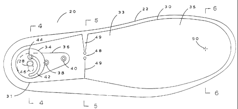
As shown the adjustable support system generally comprises
a footbed assembly 20, shim 30 and a means for moving the shim
30 transversely relative to the footbed assembly 20, comprising
cam 34 and strut 36, to adjust the cant of the shim. As shown
in FIG. 1, footbed assembly 20, having a heel portion 25, mid-
portion 27 and toe portion 29, comprises a base member 22 to
which a covering socklining 32 is secured by a suitable means
such as edge-stitching 24 to the top surface of base member 22,
a manually adjustable slotted-head camshaft 28 attached to the
base member 22, all supported by bottom member 26. Alterna-
tively, base member 22 and bottom member 26 may be a single
integral unit.
FIGS. 2 and 2A shows the above elements plus a cantably ad-
CA 02372599 2001-12-14
WO 00/76335 PCTIUSOO/16280
-5-
justable shim 30. The shim 30 has a heel portion 31, a mid-
portion 33, and a toe portion 35, corresponding to portions 25,
27, and 29 of the footbed assembly 20 (see FIG. 1), respectively.
In addition, an adjustable circular cam 34 is shown as being
movably connected to an adjustable strut 36, with strut 36
attached to the bottom member 26 by means of rivet 38 and to the
shim 30 by means of rivet 40. Cam 34 is fixedly attached to
camshaft 28 by which it can be manually rotated to adjust the
effective transverse cant of the flat top surface of shim 30 and
sock 32 which covers shim 30 relative to the flat bottom surface
of footbed assembly 20, as will be further described with
reference to the following FIGS. 3 through 15, inclusive.
FIG. 3 shows a plan view of footbed assembly 20 wherein shim
30 has been transversely adjusted with a maximum of such
adjustment occurring at shim hinge portion 48 (line 5-5) as
hinged shim 30 articulates at said hinge 48, with shim heel
portion 31 rotating around camshaft 28 at the heel end of footbed
assembly 20, and rotating generally around forepart axis 50 with
such adjustment. As shown, the shim hinge is formed by two slots
49 in the shim 30. This so-adjusted orientation of shim 30
towards one side of the adjustable support system results from
the manual rotational adjustment of camshaft 28 and cam 34
fixedly attached thereto, with concurrent adjustment thereby of
the longitudinal angle of strut 36 as it is rotated around its
rivet 38 connection to bottom member 26 thereunder, said change
in strut 36 angle resulting from the change in radial distance
of rivet 44 from the rotational axis of camshaft 28 and cam 34
as they together adjustably move said rivet 44 and the rearward
portion of strut 36 to which rivet 44 is fixedly attached, thus
adjusting strut 36 angularly thereby as rivet 44 is moved
radially by the offset arcuate cam-slot 42 by which rivet 44 is
contained and so radially adjusted. The construction which per-
mits this operation provides for rivet 38 to be attached through
strut 36, shim 30 and footbed bottom member 26 to allow rotary
adjustment of strut 36 and shim 30 therewith, as controlled by
rotary adjustment of cam 34, which is attached to all parts by
camshaft 28, and which cam 34 is also attached to strut 36 only
CA 02372599 2001-12-14
WO 00/76335 PCT/US00/16280
-6-
by rivet 44, radially adjusted by means of arcuate slot 42 in cam
34.
While FIG. 3 shows slots 49 located toward the rear of the mid-
portion of shim 30, the slots may be located anywhere in the mid-
portion, including farther forward, i.e. closer to the toe
portion, if desired.
The predominant motion of the shim 30 is transverse to the
width of the shoe. Accordingly, the shim 30 may be slightly
shorter than or substantially the same length (not shown) as the
footbed assembly. The mid-portion of the shim must be narrower
than the corresponding mid-portion location of the footbed
assembly. The amount of narrowing will depend upon the specific
design and the degree of cant adjustment to be provided.
Generally, however, the mid-portion of the shim is about 5 to
about 35% narrower than the mid-portion of the footbed assembly.
FIGS. 4-6 show transverse sections of footbed assembly 20
at a maximum adjustment for pronation, having at this adjustment
a mid-portional cant of four degrees of so-called "positive" cant
angle from the horizontal on the medial side of footbed assembly
20, said cant referring to the transverse angular attitude of the
relatively flat top surface of shim 30 covered by socklining 32,
when compared to the flat bottom surface of the footbed assembly
20. This canting results from the laterally adjusted movement
of the transversely convexly contoured bottom surface of shim 30
in the mid-portion as it is so adjustably repositioned relative
to the matching transversely concavely contoured top surface 24
of footbed assembly 20 at the corresponding mid-portion directly
thereunder, supporting said shim 30 at its variously adjusted
positions.
FIGS. 7-10 similarly show views of the same elements of
footbed 20 as they would appear adjusted to the maximum of four
degrees of negative cant, as could be required for proper
correction of the less frequent condition of excessive supination
of the foot.
CA 02372599 2001-12-14
WO 00/76335 PCT/US00/16280
-7-
It should be noted that while the drawings disclose a pres-
ently preferred range of canting adjustment of from four degrees
positive, infinitely adjustable by the adjustment means
described, to the opposite limit of four degrees negative cant,
other ranges and areas of maximum and/or minimum canting
adjustment are optionally available with appropriate revisions
to the design of adjustment means, hinge portions and axes of
rotation therein, and are to be considered equivalent to the
invention therefor.
FIGS. 11-17 show additional views of the canting adjustment
means, with FIGS. 11 and 12 showing respectively the plan view
and side elevational cross-section of shim 30 taken on line 12-12
of FIG. 11. FIGS. 13-15 show transverse elevational cross-sec-
tions of said shim 30 taken respectively on lines 13-13, 14-14
and 15-15 of FIG. 12. FIG. 16 shows cam 34 with cam-slot 42 and
an opening for camshaft 28 therein. FIG. 17 shows strut 36 with
slot 46 therein designed to eliminate interference by camshaft
28 during the aforementioned angular adjustment of said strut 36.
FIG. 17 also shows openings 38a, 40a, and 44a designed to retain
rivets 38, 40, and 44 respectively.
While the elements of footbed assembly 20 may be
manufactured from a wide range of suitable materials, those
presently preferred include fabric for socklining 32 of
Cambrelle fabric, available from Faytex, Inc., Weymouth, MA.
Footbed base 22 and canting shim 30 are both of polyurethane,
custom-molded by Atlantic Thermoplastics, Blackstone, MA or
others. Bottom element 26 is of fabric-faced Surlyn extruded
sheet material available from Foss, Inc., Hampton, NH. All metal
parts are to be preferably of stainless steel, with cam 34 and
strut 36 stamped from .015" sheet material, with such stampings
supplied by Peter Forg Mfg., Somerville, MA and camshaft 28 by
Accurounds, Inc., Avon, MA and others.
It should be understood that the above disclosures represent
only one application of the concepts of this invention and that
other designs for use in footbeds and shoe bottom assemblies are
CA 02372599 2001-12-14
WO 00/76335 PCT/US00/16280
-8-
considered possible and equivalents under the teachings of this
invention.