Language selection

Search

Patent 2372769 Summary

Third-party information liability

Some of the information on this Web page has been provided by external sources. The Government of Canada is not responsible for the accuracy, reliability or currency of the information supplied by external sources. Users wishing to rely upon this information should consult directly with the source of the information. Content provided by external sources is not subject to official languages, privacy and accessibility requirements.

Claims and Abstract availability

Any discrepancies in the text and image of the Claims and Abstract are due to differing posting times. Text of the Claims and Abstract are posted:

  • At the time the application is open to public inspection;
  • At the time of issue of the patent (grant).
(12) Patent: (11) CA 2372769
(54) English Title: MULTI-PIECE FEEDERHOUSE BUSHING RETAINER
(54) French Title: FIXATION A DEUX PIECES POUR BAGUE D'ENGRENEUR DE MOISSONNEUSE-BATTEUSE
Status: Deemed expired
Bibliographic Data
(51) International Patent Classification (IPC):
  • A01D 41/12 (2006.01)
  • A01D 61/00 (2006.01)
(72) Inventors :
  • MACKIN, RYAN PATRICK (United States of America)
  • FOERDERER, ANDREW JAMES (United States of America)
  • REMLEY, RICHARD C. (United States of America)
  • SIGNER, TODD NEIL (United States of America)
  • HAAR, THOMAS BERNARD (United States of America)
  • MELTON, MARK ALAN (United States of America)
(73) Owners :
  • DEERE & COMPANY (United States of America)
(71) Applicants :
  • DEERE & COMPANY (United States of America)
(74) Agent: BORDEN LADNER GERVAIS LLP
(74) Associate agent:
(45) Issued: 2004-11-09
(22) Filed Date: 2002-02-22
(41) Open to Public Inspection: 2002-08-28
Examination requested: 2002-02-22
Availability of licence: N/A
(25) Language of filing: English

Patent Cooperation Treaty (PCT): No

(30) Application Priority Data:
Application No. Country/Territory Date
09/795,752 United States of America 2001-02-28

Abstracts

English Abstract

A two-piece retainer for securing a pivot tube of a combine feederhouse to a combine frame, having a first piece made of a polymer material and a second piece made of a metal material.


French Abstract

Un dispositif de retenue à deux pièces pour fixer un tube pivot d'un engreneur de moissonneuse-batteuse à un châssis de moissonneuse-batteuse, présentant une première pièce en matériau polymère et d'une deuxième pièce en matériau métallique.

Claims

Note: Claims are shown in the official language in which they were submitted.


Claims

1. A mechanism for pivotally attaching a feederhouse to a frame of a combine
vehicle, comprising:
a pivot member coupled with the feederhause, and
a retainer mechanism that retains the pivot member with the frame of the
combine
vehicle, said retainer mechanism comprises a first piece that abuts the pivot
member, and a
second piece that operatively retains the first piece against the pivot
member, said second
piece being fixable to the frame of the combine vehicle, wherein the first
piece is a polymer
material and the second piece is a metal material.

2. The mechanism according to claim 1, and further comprising a notch formed
in
the frame of the combine for receiving the pivot member.

3. The mechanism according to claim 2, wherein the second piece is positioned
across an opening in the notch, and the first and second pieces confine the
pivot member
within the notch.

4. The mechanism according to claim 1, wherein the pivot member is generally
cylindrical, and the first piece includes an arced portion which abuts the
pivot member.

5. The mechanism according to claim 4, wherein the second retainer piece
includes
a peg member received within an opening defined in the frame of the combine,
and the
second retainer is pivoted into position against the first piece after the peg
member is
positioned within said opening.

6. The mechanism according to claim 5, and further comprising a bolt member
which
secures the second piece to the frame of the combine after the peg member has
been
positioned in said opening.

7. The mechanism according to claim 1, and further comprising a support
structure
extending between the pivot member and the feederhouse, the support structure
having
spaced side walls between which the pivot member is fixed, the spacing of the
side walls
being larger than a width of a portion of the frame of the combine to which
the pivot member
is operatively attached, and the first piece is generally as wide as the
spacing of the side
walls.

8. The mechanism according to claim 7, wherein the first piece is positioned
between the side walls.

9. The mechanism according to claim 7, wherein the second piece is narrower
than
the spacing between the side walls.

10. The mechanism according to claim 9, wherein the second piece is positioned

7


between the side walls.

11. The mechanism according to claim 9, wherein the first and second pieces
are
positioned between the side walls.

12. A mechanism for pivotally attaching a feederhouse to a frame of a combine
vehicle, comprising:
a generally cylindrical pivot member coupled with the feederhouse,
a notch formed in the frame of the combine for receiving the pivot member,
a support structure extending between the pivot member and the feederhouse,
the
support structure having spaced side walls between which the pivot member is
fixed, the
spacing of the side walls being larger than a width of a portion of the frame
of the combine to
which the pivot member is operatively attached, and
a retainer mechanism that retains the pivot member with the frame of the
combine
vehicle, said retainer mechanism comprises a first piece that includes an
arced portion which
abuts the pivot member, and a second piece fixable to the frame of the combine
vehicle, the
first piece extends across an opening of the notch and operatively retains the
first piece
against the pivot member, said first and second pieces being positioned
between the side
walls of the support structure and confine the pivot member within the notch,
said second
piece being fixable to the frame of the combine vehicle, the first piece is
substantially as
wide as the spacing of the side walls and the second piece is substantially
narrower than the
spacing between the side walls.

13. The mechanism according to claim 12, wherein the first piece is a polymer
material.

14. The mechanism according to claim 13, wherein the second piece is a metal
material.

15. The mechanism according to claim 12, wherein the second retainer piece
includes a peg member received within an opening defined in the frame of the
combine, and
the second piece is pivoted into position against the first piece after the
peg member is
positioned within said opening.

16. The mechanism according to claim 15, and further comprising a bolt member
which secures the second piece to the frame of the combine after the peg
member has been
positioned in said opening.

17. A mechanism for pivotally attaching a feederhouse to a frame of a combine
vehicle, comprising:
a generally cylindrical pivot member coupled with the feederhouse,
a notch formed in the frame of the combine for receiving the pivot member,
a support structure extending between the pivot member and the feederhouse,
the
support structure having spaced side walls between which the pivot member is
fixed, the

8


spacing of the side walls being larger than a width of a portion of the frame
of the combine to
which the pivot member is operatively attached,
a retainer mechanism that retains the pivot member with the frame of the
combine
vehicle, said retainer mechanism comprises a first piece of a polymer material
having an
arced portion which abuts the pivot member, and a second piece of a metal
material fixable
to the frame of the combine vehicle, the first piece extends across an opening
of the notch
and operatively retains the first piece against the pivot member, said first
and second pieces
being positioned between the side walls of the support structure and confine
the pivot
member within the notch, said second piece being fixable to the frame of the
combine
vehicle, the first piece is substantially as wide as the spacing of the side
walls and the
second piece is substantially narrower than the spacing between the side
walls,
the second piece includes a peg member received within an opening defined in
the
frame of the combine, the second piece being pivoted into position against the
first piece
after the peg member is positioned within said opening, and
a bolt member which secures the second piece to the frame of the combine after
the
peg member has been positioned in said opening.

9

Description

Note: Descriptions are shown in the official language in which they were submitted.


CA 02372769 2002-02-22
MULTI-PIECE FEEDERHOUSE BUSHING RETAINER
Background of the Invention
Conventional combines include a header attached to the front of the combine
vehicle.
The header engages and cuts the crop as the combine vehicle travels through an
agricultural field. The cut crop is then directed to the middle of the header
where it is
directed upwardly and rearwardly through a feederhouse. The feederhouse
directs the cut
crop rearwardly to the combine vehicle for further processing. The header and
feederhouse
are generally rigidly coupled together during operation. The feederhouse is
coupled with the
combine vehicle such that the feederhouse and header can pivot with respect to
the
combine vehicle.
Structure is provided for allowing the header and feederhouae to pivot with
respect to
the combine vehicle. Fixed to conventional feederhouses are a pair of
laterally spaced pivot
tubes. Structure at the front of the combine vehicle is provided for Engaging
these pivot
tubes. The structure at the front of the combine vehicle serves to hold the
pivot tubes while
allowing the pivot tubes to pivot with respect to the combine vehicle. The
feederhouse and
header are thereby allowed to pivot with respect to the combine vehicle.
Some headers are automatically controlled by devices which pivot the header in
response to undulations in ground contour. Headers provided with such control
devices are
typically pivoted relatively frequently during operation. Each time the header
is pivoted with
respect to the combine vehicle, the pivot tube pivots slightly within the
structure that is
holding it to the combine. The pivot tubes, as well as the structure at the
front of the
combine that holds the pivot tubes, rub against each other and tend to
experience a large
amount of wear due to the frequent pivoting of the header across undulating
ground
contours. The problem of wear is further exacerbated by. the use of wider and
wider headers.
The wider headers weigh more than narrower headers, and therefore the greater
weight of
the wider headers causes even greater wear.
One type of pivot tube mechanism includes a casting having spaced apart side
walls
that support respective left and right ends of a pivot tube. To attach a
header and
feederhouse to a combine vehicle an operator drives the combine vehicle toward
the
feederhouse from behind until the pivot tubes are positioned within V-shaped
notches
farmed in the front portion of the combine vehicle framework. The pivot tubes
are then
captured or conttned in position within the notch by fixing a retainer in
position across the
opening of the notch. Conventional combines provide a retainer having a lower
peg portion
that is received within a mating opening in the lower portion of the notch. A
bolt can then be
tightened on the upper portion of the retainer and into a threaded opening at
the top portion
of the notch to thereby fix the retainer in position to effectively close the
open portion of the


CA 02372769 2002-02-22
V-shaped notch and confine the pivot tube in proper position within the V-
shaped notch.
The width of the pivot tube and the spacing of the casting side walls is
slightly greater
than the thickness of the framework that forms the notch. This alloys
clearance for the
framework to be inserted between the side walls of the casting and facilitates
easy insertion
of the pivot tube into the notch. Because the framework is narrower than the
spacing of the
casting side walls, the pivot tube and casting can shift laterally slightly
during operation. The
retainer has a width that is no greater than the width of the framework and
thereby can be
positioned in proper position in alignment with the peg opening and the
threaded opening
regardless of the lateral position of the pivot tube and casting.
It would therefore be desirable to provide a pivot tube and associated
structure at the
front of the combine for holding the pivot tube and that is well adaptad for
withstanding the
frequent pivoting motion that results from use of controls that adjust the
orientation of the
header over undulating ground contours. It would also be desirable to provide
such a
mechanism that is well adapted for withstanding the increased loads associated
with the
increased weight of relatively wide headers. It would also be desirable to
provide such a
mechanism that is capable of being retrofitted to existing combines in a cost
effective
manner. It would be desirable for such a mechanism to be adapted for use with
a casting
having side walls spaced slightly wider than the thickness of the frarnework
that forms the
notch for receiving the pivot pin.
Summary of the Invention
The present invention provides a two piece retainer structure for securely
confining a
feederhouse pivot tube within a V-shaped notch defined in a combine frame
structure. A first
retainer piece is made of a polymer material and includes a relativel~r large
arced portion that
abuts a large area of the pivot tube. The first retainer piece is generally as
wide as the side
walls of the casting that holds the pivot tube, and therefore the first
rntainer abuts the pivot
tube across a relatively wide area. A second retainer piece abut the first
retainer piece and
is coupled to the combine vehicle frame by way of a peg member positioned
within an
opening in the frame and a bolt member that secures the top portion of the
second retainer
piece to the combine frame.
The two-piece design of the retainer mechanism according to~ the present
invention
allows different materials to be utilized to thereby enhance the wear
characteristics and
generally allow the mechanism to resist wear better. The two piece retainer
according to the
present invention operatively abuts the pivot tube across a relatively large
surface area to
2


CA 02372769 2002-02-22
better transmit forces and to better resist friction and wear. The two piece
retainer is adapted
to be retrofitted to existing combines already in use which include ~~ similar
type of casting,
pivot tube, V-shaped notch and attaching geometry.
Brief Description of the Drawings
Figure 1 is a schematic side view of a combine vehicle having a header and
feederhouse and the pivotal connection mechanism according to the present
invention.
Figure 2 is a perspective view of the assembled pivotal connection between the
combine vehicle and the feederhouse.
Figure 3 is a perspective view of the assembled pivotal connection of Figure
2, with a
portion of the casting removed to illustrate the pivot tube, first retainer
piece, and second
retainer piece and V-shaped notch according to the present inventi~~n.
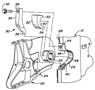
Figure 4 is an exploded view of the pivotal connection struci:ure according to
the
present invention, with a portion of the casting removed to show the: pivot
tube.
Figure 5 is a top view of the assembled pivotal connection structure according
to the
present invention.
Description of the Preferred Embodiment
Referring now to Figure 1, there is shown a combine vehicle 10 having a header
12
and feederhouse 14 mounted to the front of the combine vehicle 10. During
operation the
combine 10 travels forward in a field wherein a crop is to be harvesl:ed. The
header 12
engages and cuts the crop, and directs the cut crop to the center of the
header 12. Once in
the central portion of the header 12 the harvested crop is directed upwardly
and rearwardly
through the feederhouse 14 for further processing within the combine vehicle
10.
The combine 10 may be provided with a control mechanism 16 that automatically
controls the position of the header 12 and feederhouse 14 with respect to the
combine
vehicle 10. Hydraulic cylinders 18 may be provided which pivot the header 12
and
feederhouse 14 with respect to the combine vehicle 10 to thereby automatically
accommodate undulations in ground contour.
Rigidly fixed to respective sides of the feederhouse 14 are a pair of support
structures or castings 20 which each include a cylindrical pivot member or
tube 22 rigidly
fixed therein. The casting 20 includes a pair of laterally spaced side walls
24 between which
the pivot tube 22 extends. The pivot tubes 22, castings 20, feederhouse 14,
and header 12
are rigidly fixed to each other and therefore pivot as a unit during
operation. The pivot tube
3


CA 02372769 2002-02-22
22 is received within a V-shaped notch 26 formed in a frame portion 28 at the
front of the
combine vehicle 10. The pivot tube 22 is held in place and confined within the
notch 26 by a
two piece retainer mechanism 30 according to the present invention. A first
retainer piece
32 is made of a polymer material is positioned directly against the pivot tube
22 within the V-
shaped notch 26. A second retainer piece 34 is a cast metal part and includes
a peg portion
36 at its lower end and an opening 38 in its upper portion. The pey portion 36
is received
within an opening 40 proximate the lower portion of the V-shaped notch 26. A
bolt 42 is
positioned within the opening 38 at the top of the second retainer piece 34
and is received
within a threaded opening 44 proximate the upper portion of V-shaped notch 26
. When
assembled the first and second retainer pieces 32, 34 confine the pivot tube
22 within the V-
shaped notch 26 and allow the pivot tube 22 to pivot with respect to the frame
28 and
combine vehicle 10 to thereby allow the header 12 and feederhouse 14 to be
pivoted by the
automatic controller 16.
The first retainer piece 32 is confined in its proper position by abutment
against the
pivot tube 22, the upper 46 and lower 48 surfaces of the V-shaped notch 26,
the side walls
24 of the casting 20 and the second retainer piece 34. The back surface of the
first retainer
piece 32 and the front surface of the second retainer piece 34 have matching
arced shapes
to better transmit forces therebetween and reduce wear between those two
parts.
To assemble the mechanism according to the present invention, the operator
drives
the combine vehicle 10 toward the feederhouse 14 so that the V-shaped notches
26 receive
the pivot tubes 22. The first retainer member 32 is then placed in position
against the pivot
tube 22. While holding the first retainer piece 32 in place, the operator
inserts the peg
portion 36 of the second retainer 34 into the opening 40 proximate the lower
end 48 of the V-
shaped notch 26 and then pivots the second retainer 34 upwardly until the
opening 38 at the
top of the second retainer piece 34 is aligned with the threaded opening 44
proximate the
upper end 46 of the V-shaped notch 26. The operator then inserts the bolt 42
into the
opening 38 in the second retainer 34 and threads it into the threaded opening
44 in the
frame structure 28. The pivot tube 22 is then securely confined in proper
position, and the
operator then repeats this procedure to secure the other pivot tube 22 within
the other V-
shaped notch 26.
The first retainer piece 32 has a width generally equal to the spacing between
the
side walls 24 of the casting 20. This allows the first retainer 32 to contact
the pivot tube 22
across a relatively large area. The second retainer piece 34 is approximately
as wide as the
frame structure 28 that defines the V-shaped notch 26. This allows the second
retainer
4


CA 02372769 2002-02-22
piece 34 to be placed in proper position regardless of the lateral-position of
the casting 20
with respect to the frame structure 28 when the pivot tube 22 is positioned
within the V-
shaped notch 26.
The retainer mechanism 30 according to the present invention includes a
plurality of
pieces, and therefore the respective pieces can be made of different materials
such as metal
and polymer so as to enhance the wear characteristics of the retainer assembly
30. The
retainer pieces can be manufactured of materials that effectively rea!uce the
wear between
the pivot tube 22, first retainer piece 32 and second retainer piece 3.4, and
that also provide
enough structural strength to withstand the loads imparted to the various
parts during
operation of the combine 10. The first retainer piece can be manufactured of a
polymer
material such as a Verton branded material manufactured by a company known as
L.N.P.
The first retainer may also be manufactured of a powdered metal material.
The first retainer piece 32 has an arced portion 50 that engactes the pivot
tube 22
across a large portion of the radius of the pivot tube 22. Because the first
retainer piece 32
can be linearly slid into position against the pivot tube 22, it can be
designed with a longer
arced portion 22. Conventional single piece retainer mechanisms had to be
pivoted into
position after the peg portion was positioned within an opening, and
~rherefore the arced
portion of conventional single piece retainers could not include an ar~~ed
portion that
extended very far because the outer edge of the arced portion would be blocked
by the pivot
tube as it is swung into position. Therefore, providing a first retainer piece
32 that is
separate from the second retainer piece 34 in accordance with the present
invention allows
the use of an arced portion 50 that engages the pivot tube 22 across a
relatively large
portion of the pivot tube's radius. The larger arced portion 50 helps
clistribute the forces from
the pivot tube 22 throughout the first retainer piece 32, and enhance:. the
wear
characteristics of the assembly. The upper and lower portions 52 and 54 of the
arced
portion 50 in particular are helpful for placing material where large forces
are transmitted
from the pivot tube 22 to the retainer 30 at those locations.
The two-piece retainer mechanism 30 according to the present invention is
adapted
to be retrofitted to existing combines having single piece retainer
mechanisms. The two-
piece retainer 30 according to the present invention includes a first retainer
piece 32 that fits
within the spacing of the side walls of existing castings. Furthermore, the
second retainer
piece 34 has a peg member 36 and opening 38 that are in the same location as
conventional
single piece retainers, and therefore the first and second pieces 32, 34 of
the two-piece
retainer 30 according to the present invention will fit on conventional
combines having similar
5


Image

Representative Drawing
A single figure which represents the drawing illustrating the invention.
Administrative Status

For a clearer understanding of the status of the application/patent presented on this page, the site Disclaimer , as well as the definitions for Patent , Administrative Status , Maintenance Fee  and Payment History  should be consulted.

Administrative Status

Title Date
Forecasted Issue Date 2004-11-09
(22) Filed 2002-02-22
Examination Requested 2002-02-22
(41) Open to Public Inspection 2002-08-28
(45) Issued 2004-11-09
Deemed Expired 2016-02-22

Abandonment History

There is no abandonment history.

Payment History

Fee Type Anniversary Year Due Date Amount Paid Paid Date
Request for Examination $400.00 2002-02-22
Registration of a document - section 124 $100.00 2002-02-22
Application Fee $300.00 2002-02-22
Maintenance Fee - Application - New Act 2 2004-02-23 $100.00 2004-02-03
Final Fee $300.00 2004-08-27
Maintenance Fee - Patent - New Act 3 2005-02-22 $100.00 2005-02-02
Maintenance Fee - Patent - New Act 4 2006-02-22 $100.00 2006-01-30
Maintenance Fee - Patent - New Act 5 2007-02-22 $200.00 2007-01-30
Maintenance Fee - Patent - New Act 6 2008-02-22 $200.00 2008-01-30
Maintenance Fee - Patent - New Act 7 2009-02-23 $200.00 2009-01-30
Maintenance Fee - Patent - New Act 8 2010-02-22 $200.00 2010-02-02
Maintenance Fee - Patent - New Act 9 2011-02-22 $200.00 2011-01-31
Maintenance Fee - Patent - New Act 10 2012-02-22 $250.00 2012-01-30
Maintenance Fee - Patent - New Act 11 2013-02-22 $250.00 2013-01-30
Maintenance Fee - Patent - New Act 12 2014-02-24 $250.00 2014-02-17
Owners on Record

Note: Records showing the ownership history in alphabetical order.

Current Owners on Record
DEERE & COMPANY
Past Owners on Record
FOERDERER, ANDREW JAMES
HAAR, THOMAS BERNARD
MACKIN, RYAN PATRICK
MELTON, MARK ALAN
REMLEY, RICHARD C.
SIGNER, TODD NEIL
Past Owners that do not appear in the "Owners on Record" listing will appear in other documentation within the application.
Documents

To view selected files, please enter reCAPTCHA code :


To view images, click a link in the Document Description column. To download the documents, select one or more checkboxes in the first column and then click the "Download Selected in PDF format (Zip Archive)" or the "Download Selected as Single PDF" button.

List of published and non-published patent-specific documents on the CPD .

If you have any difficulty accessing content, you can call the Client Service Centre at 1-866-997-1936 or send them an e-mail at CIPO Client Service Centre.


Document
Description 
Date
(yyyy-mm-dd) 
Number of pages   Size of Image (KB) 
Abstract 2002-02-22 1 7
Representative Drawing 2002-05-17 1 14
Claims 2003-04-03 3 144
Cover Page 2004-10-15 1 39
Description 2002-02-22 6 338
Claims 2002-02-22 3 152
Drawings 2002-02-22 3 89
Cover Page 2002-08-16 1 37
Assignment 2002-02-22 5 187
Prosecution-Amendment 2003-04-03 5 224
Correspondence 2004-08-27 1 25