Note: Descriptions are shown in the official language in which they were submitted.
CA 02373087 2001-11-09
WO 00/68545 PCT/AU00/00317
DRIVE MECHANISM AND ROTARY DISPLACER FOR HOT AIR ENGINES
The present invention relates generally to a drive mechanism for use with
powered
reciprocating members. One particular application of the present invention
concerns the use
of the drive mechanism in Stirling engines. It will be appreciated however
that the drive
mechanism has other applications and may be used in conjunction with many
other types of
apparatus containing powered reciprocators.
The Stirling engine is named in honour of Robert Stirling, who in the early
1800s
proposed a hot-air engine that was capable of converting energy into useful
work. Stirling
engines have in this century undergone significant analysis and development as
they are seen
as having a number of advantages over the common and well known internal
combustion
engine.
The Stirling cycle engine operates on a closed regenerative thermodynamic
cycle
involving periodic compression and expansion of a working fluid at different
temperature levels.
It typically includes the following components: one or more cylinders; a
displaces and a power
piston which move within the one or more cylinders; a working fluid control
loop; a regenerator
or other heat exchangerlcooler mechanism; and a drive mechanism. Stirling
engines connected
to a drive mechanism to convert linear motion of pistons into rotary motion
are termed
kinematic engines. Stirling kinematic engines can adopt a variety of
piston/cylinder
configurations including what are known as an alpha configuration, a beta
configuration and a
gamma configuration. In the alpha configuration, there are separate cylinders
for the expansion
and compression spaces and each contains a piston. In a beta co~guration the
displaces and
power pistons run in the same cylinder and in a gamma configuration the
displacers and power
pistons are housed respectively in separate cylinders. In another form of
Stirling engine, the
reciprocating displaces piston is replaced by a rotary displaces, known as a
rotary displaces
engine.
While the Stirling engine in its basic form predates the internal combustion
engine and
has a number of applications, it has not found universal applicability due to
a number of
CA 02373087 2001-11-09
WO 00/68545 PCT/AU00/00317
-2-
problems, including a lack of power output. If such problems could be
addressed, it is generally
believed that the Stirling engine could gain widespread acceptance in many
applications. This
is especially so in the modern era, where the features of the Stirling engine,
including high
thermal efficiency employing heat from any source, little or no emissions and
quiet operation,
make it suitable for a number of applications.
A number of drive mechanisms have been proposed for use in Stirling engines,
including simple crankshafts, rhombic drives, Ross linkages, and swash plates.
Cam drives have
also been proposed, see for example US 5442913 and US 5533335. In the present
invention,
another drive mechanism for use with a Stirling cycle engine is described that
allows some of
the advantages of the Stirling cycle to be realised.
According to one aspect of the present invention there is provided a drive
mechanism
for use in the transmission of power from a plurality of linear reciprocating
power generating
elements to a rotating output element, the drive mechanism including a drive
cam member
having a cam follower guiding contour extending along the cam member; a drive
cam follower
operatively connected to each power generating element, each follower being
adapted to engage
the cam follower guiding contour throughout each reciprocation cycle of the
power generating
elements, said drive cam follower guiding contour following a generally
sinusoidal profile on
the surface of the drive cam member, the profile including a series of lobes
forming peaks and
troughs with intermediate regions therebetween, the peak to peak amplitude of
the substantially
sinusoidal profile of the cam follower guiding contour on the surface of the
drive cam
substantially corresponding to the stroke amplitude of the stroke of the
reciprocating power
generating elements, there being at least three drive cam followers spaced
along the contour
from one peak to an adjacent trough.
It is to be understood that by the term "sinusoidal" is meant any suitable
profile which
includes a series of peaks and troughs joined by intermediate regions; that is
the profile does not
necessarily need to be sinusoidal in the strict mathematical sense.
In one form of the invention, the drive cam member includes a generally
cylindrical
CA 02373087 2001-11-09
WO 00/68545 PCT/AU00/00317
-3-
body which is rotatable about its central axis, the cam follower guiding
contour extending along
a surface of the cylindrical body. In one arrangement the cam follower guiding
contour maybe
on the outer surface of the cam body. In another arrangement the cam follower
guiding contour
is on the inner surface thereof. The cam follower guiding contour may for
example include an
upstanding member or a groove on the surface of the cam body.
The drive cam member may be operatively connected to a drive shaft such that
rotation
of the cam member causes rotation of the drive shaft. In one embodiment the
reciprocating
elements are disposed in a generally annular arrangement with each being
equally
circumferentially spaced from each of its adjacent reciprocating elements. In
one form the
reciprocating elements include pistons disposed within respective cylinders
for reciprocating
motion therein.
The drive mechanism may include a main body portion, the drive cam member
being
mounted for rotation relative thereto. The mechanism may further include a
carriage associated
with each drive cam follower, each cam follower being operatively connected to
its associated
carriage. A track may be provided on the main body, each carriage being
mounted for linear
movement along the track. In one form, the track includes a plurality of
groups of rods, each
group being associated with a respective carriage, each carnage including
guide elements which
are receivable on the rods for sliding movement therealong. In another form,
the track includes
a plurality of grooves in the main body each groove being associated with a
respective carnage,
each carriage being receivable within a respective groove for movement
therealong.
In one application, the drive mechanism is adapted for use in a Stirling
engine. The
Stirling engine includes a plurality of adjacent cylinder assemblies, each
cylinder assembly
having associated therewith a displaces, a power piston, and a piston
connecting rod extending
from each piston, the power piston connecting rod having the associated drive
cam follower
operatively connected thereto. Each follower is adapted to engage the cam
follower guiding
contour throughout each reciprocation cycle of the power piston. There is
further provided
control means operable so that the displaces and power piston for each
assembly are in selected
phase with respect to one another. Advantageously the shape of the sinusoidal
contour can be
CA 02373087 2001-11-09
WO 00/68545 PCT/AU00/00317
-4-
altered to meet selected engine parameter requirements. For example, by
"flattening" the peaks
and troughs so as to alter the dwell time of the displacers and power pistons
the engine power
output can be increased, providing the lobes remain harmonic, that is,
identical in series
waveform.
Preferably, the cylinder assemblies are disposed in a generally annular
arrangement with
each cylinder assembly being equally circumferentially spaced from each of its
adjacent
cylinder assemblies.
In one form, each cylinder assembly includes a cylinder with the displaces and
power
piston therein, the displaces being arranged to undergo a reciprocating
motion. This is a typical
beta configuration type engine. In this form, the displaces may include a
displaces connecting
rod which is concentric within the power piston connecting rod, the displaces
connecting rod
extending through the power piston and being disposed within the power piston
connecting rod.
In this form of the invention the control means includes a linking member
which operatively
links the displaces of one assembly with the power piston of another assembly
such that the
reciprocation cycles of the assemblies and the displaces and power piston for
each assembly are
in selected phase. In one form, the power piston connecting rod is formed at
least in part from
a tubular member into which the distal end of the displaces connecting rod
extends.
25
In another form, each displaces is disposed within a separated displaces
cylinder and
each associated power piston is disposed within a separate power piston
cylinder, the cylinders
of each associated displaces and power piston being operatively connected by a
gas transfer
passage. This is a typical gamma configuration type engine.
There may further be provided electrically operable ball valve means in each
gas transfer
passage for controlling the power output.
According to one form of the invention the displacers are disposed within
their
associated displaces cylinder for reciprocating movement therein. In this
particular form of the
invention the control means may include a displaces cam member having a
displaces cam
CA 02373087 2001-11-09
WO 00/68545 PCT/AU00/0031'7
-5-
follower contour extending therealong. A displaces connecting rod may be
provided which
extends from each displaces and has a displaces cam follower operatively
connected thereto
which is adapted to engage the displaces cam follower contour. The drive cam
member and the
displaces cam member are arranged such that the reciprocation cycles of the
assemblies are in
selected phase.
In the aforementioned form of the invention each of the cam members may be
operatively connected to the output shaft. Rotation of the drive cam member is
adapted to
cause rotation of the output shaft which in turn causes rotation of the
displaces cam member.
Preferably, the displaces cam member is operatively connected to the output
shaft through a
gear train which may for example, including a plurality of planetary gears and
an associated ring
gear on the displaces cam member.
According to another form of the invention each of the displacers is disposed
within
their associated cylinders for individual rotational movement therein. In this
rotary displaces
form of the invention the displacers are in the form of vanes which are
generally semi-circular
in cross-sectional shape and extend along the cylinder and are rotatable about
the longitudinal
axis thereof. Preferably, the front faces of the vanes are recessed. In this
rotary vane displaces
form of the invention the control means includes a gear train which may
include a ring gear
operatively connected to the drive shaft and a series of pinion gears each
being associated with
a respective displaces so that rotation of the pinion gear causes rotation of
the vane according
to selected phase.
The above mentioned displaces vanes form a separate invention in their own
right.
Thus according to another aspect of the present invention there is provided a
displaces for a
Stirling engine, the displaces including an elongated vane which in use is
mounted for rotation
within a cylinder, the vane including a generally semi-circular shaped body
when viewed in
cross-section having a front face and a rear face which is substantially the
same curvature of the
cylinder with which it is associated. Preferably, the cylinder walls are
knurled with rings of
ridges and grooves to increase the action of the working fluid.
CA 02373087 2001-11-09
WO 00/68545 PCT/AU00/00317
-6-
Preferably, the front face of each vane includes inwardly formed recesses
disposed on
opposite sides of the axis of rotation of the vane.
In the latter two mentioned forms of the invention the control means may
further include
an adjustment mechanism which is operable to control the direction of rotation
of the drive
output shaft by adjusting the timing of the displacers relative to their
associated power pistons.
The adjustment mechanism may include a planetary gear support sleeve which is
connected
to the drive shaft for rotation therewith. The sleeve supports the planetary
gears thereon. The
planetary gear support sleeve may be disposed within a ring gear support
sleeve which carries
a ring gear. Each sleeve may have cooperating slots therein which are adapted
to receive a pin
therein the pin being mounted on a plug arranged for linear movement within
the sleeve.
Movement of the pin may be controlled by a screw element which is operated by
a control
actuator.
In normal operation the drive output shaft, the sleeves, the cam member via
the
planetary gears and ring gears rotate as a unit. By rotation of the control
actuator and screw
element the pin can move upwards or downwards along the longitudinal axis of
the drive output
shaft thereby causing relative rotation between the two sleeves and thereby
adjusting the timing
of reciprocation of the displacers. As a result the engine output can be
driven in a normally
forward or reverse direction or adopt a neutral position.
The number of peaks of the substantially sinusoidal cam follower guiding
contour sets
the preferred number of cylinders of the associated Stirling engine. For
instance, where the
guiding surface has four peaks (i.e., a two cycle substantially sinusoidal
curve configuration),
the Stirling engine preferably has eight power pistons, with the cam follower
of each power
piston connecting rod being equally separated from its adjacent cam followers.
The result is that
each pair of pistons are in effect arranged 90° out of phase when
undergoing reciprocation
within their respective cylinders. The angular separation of the axis of each
power piston
connecting rod (where there are eight power connecting rods) will be
45° (See Fig. 29).
CA 02373087 2001-11-09
WO 00/68545 PCT/AU00/00317
_7_
Further, in the case of an engine having eight power pistons, as each power
piston will
have four strokes per one revolution of the cam, the total number of power
strokes of the eight
power pistons is thirty two strokes per cam revolution. As the number of peaks
of the guiding
contour increases, so the number of power pistons that engage the drive
apparatus can increase.
This in turn leads to an increase in the number of power strokes per
revolution of the cam as
illustrated by the following table:
~ ct~~ ~n;t~Tr'~ '°"~~' a i , ;~ ,
8 4 16 (total strokes 32)
12 6 36 (total strokes 72)
16 8 64 (total stokes 128)
20 10 100 (total strokes 200)
It can be readily envisaged that as the number of peaks increase, the number
of power
pistons that can be used to drive the drive apparatus also increase in line
with the relationship
described above.
One particularly advantageous application of the drive mechanism according to
the
invention is in relation to its use as part of an electric generator. To this
end the drive cam
member may be configured to form an armature which is adapted to co-operate
with a stator for
the generation of electricity. The drive cam member may include a plurality of
permanent
magnets disposed along the surface of the drive cam member which are arranged
to co-operate
with a stator so that relative movement between the two parts will cause
electricity generation.
Preferred embodiments of the invention will be hereinbefore described with
reference
to the accompanying drawings.
Figure 1 is a schematic cut away perspective view of a Stirling engine
according to one
embodiment of the present invention;
CA 02373087 2001-11-09
WO 00/68545 PCT/AU00/00317
_g_
Figure 2 is a partially cut away view of a further part of the engine shown in
Figure 1;
Figure 3 is a schematic view of the cam member of the engine shown in Figure
1;
Figure 4 is a schematic view of one of the pistons and displacers of the
engine shown
in Figure 1;
Figure S is a cut away view of the cylinder block of the engine shown in
Figure 1;
Figure 6 is a cut away view of a further part of the engine shown in Figure 1;
Figure 7 is a schematic view of a T-slot form of cam follower carriage;
Figure 8 is a schematic view of the T-slot carriage in Figure 7 in a recessed
sleeve;
Figure 9 is a schematic view of the engine which has been laid flat for
illustrative
purposes;
Figure 10 is a schematic view of a Stirling engine according to a second
embodiment
of the present invention;
Figure 11 is a schematic side elevation of the embodiment shown in Figure 10;
Figure 12 is a schematic plan view of part of the engine shown in Figures 10
and 1 l;
Figure 13 is an illustration of the arrangement of adjacent pistons of the
engine shown
in Figures 10 to 12;
Figures 14 to 17 are schematic illustrations of the engine shown in Figures 10
to 12 with
various parts removed or cut away for the purpose of illustration;
CA 02373087 2001-11-09
WO 00/68545 PCT/AU00/00317
-9-
Figure 18 is a schematic side elevation of a third embodiment of the
invention;
Figure 19 is a schematic partially cut away view of the engine shown in Figure
18;
Figure 20 is a schematic view of a typical cylinder block for engines of the
type shown
in Figure 18;
Figure 21 is a schematic plan view of part of the cylinder block showing the
hot and
cold zones;
Figure 22 is a schematic view of a displacer vane for use in an engine of the
type shown
in Figure 18;
Figures 23 and 24 are plan views showing the timing sequence of the displacers
for
engines of the type shown in Figure 18;
Figure 25 is a schematic drawings illustrating the drive mechanism in a
particular
application where it is used as an electric generator;
Figure 26 is a schematic view of a further particular application of the
engine of the type
shown in Figure 18;
Figure 27 is a schematic view of yet a fw~ther application of the engine of
the type
shown in Figure 18;
Figure 28 is an illustration of the crank cycle for a conventional Stirling
engine; and
Figure 29 is a diagram of the cam layout for the drive mechanism according to
the
invention which simulates the crank cycle in Figure 28.
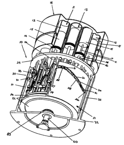
Referring to Figures 1 to 6 of the drawings there is shown a Stirling engine
CA 02373087 2001-11-09
WO 00/68545 PCT/AU00/00317
-10-
incorporating a drive mechanism according to the present invention. The
Stirling engine shown
is in the form of a beta configuration engine. The engine generally indicated
at 10 includes a
cylinder block 18 with the drive mechanism 20 at one end thereof. The drive
mechanism 20
includes a cylindrical rotating body 21 with a fixed base plate 22 operatively
connected to the
drive shaft 60. The rotating cam body 21 overlies a frame 23 which includes
end plates 24
fixed to each other by a plurality of carriage rods 35 and 36. A generally
cylindrical drive
support shell 32 as shown in Figure 2 overlies the frame 23 and cam body 21.
The engine 10
further includes a plurality of piston/cylinder assemblies, two of which are
indicated at 1 l and
13.
Each assembly includes a cylinder 12 which includes two spaces or zones, each
cylinder
having associated therewith a power piston 14 in one space and a displaces 15
in the other space.
Each power piston 14 is operatively connected to a connecting rod 16 and each
displaces is
operatively connected to a connecting rod 17. As shown in Figures 1 and 6 the
displaces
connecting rod 17 is disposed within the piston connecting rod 16 and moveable
relative thereto.
Each cylinder has a cold zone C and a hot zone H which are interconnected as
is conventional
in Stirling cycle engines. The engine operates on a closed regenerative cycle
with a periodic
compression and expansion of a working gas at different temperature levels.
The displaces 15
is arranged to transfer the working gas between the hot and cold zones so that
it acts on the
power piston 14 as the working gas volume changes.
As is conventional in Stirling engines the displaces 15 and its associated
power piston
14 in each cylinder are in effect arranged 90° out of phase with
respect to one another as
illustrated in Figure 28, with the displaces leading the power piston by
90° with respect to the
direction of rotation of the output shaft as shown in Figure 29.
The particular form of engine shown in the drawings includes 12 cylinders
which are
arranged in a circular configuration. The assemblies are equispaced from one
another by an
angle 8. In the arrangement there are twelve assemblies and 8 = 30°. It
will be appreciated that
other configurations having more or less cylinders could be used, and this
will be discussed in
more detail below. Furthermore, although as shown the cylinders 12 are
arranged in a circular
CA 02373087 2001-11-09
WO 00/68545 PCT/AU00/00317
-11-
or annular configuration, again it will be appreciated however that the
cylinders could be
arranged in other configurations such as side by side in a linear
configuration, as represented
in Figure 9.
Each of the displacers 15 is operatively coupled to the power piston of an
adjacent
piston/cylinder assembly. This is clearly shown in Figure 4 where the
displaces 15 of one
piston/cylinder assembly is operatively coupled to power piston 14 of another
piston/cylinder
assembly. Power piston 14 of assembly 13 leads displaces 15 of the assembly in
the direction
of rotation of an output shaft.
Each of the power piston connecting rods 16 is operatively connected to an
output cam
member 21 forming part of the drive mechanism which in turn is operatively
connected to the
output shaft 60.
The cam member 21 includes a generally cylindrical body (See Figure 2) having
a cam
guide 30 (Figure 3) thereon the cam body 21 (Figures 1 and 3) being in
rotation about axis X-X.
The cam guide 30 is shown on the internal surface of the body 21, however, it
can be either
in the internal surface or external surface of the cylindrical body 21. As
shown the cam guide
30 is a continuous contour having a series of lobes 25 and 26 being the peaks
or troughs of the
guide with intermediate portions 27 and 28 therebetween. As can be seen the
contour of the
cam guide 30 is generally sinusoidal in shape.
The configuration of the various portions of the cam guide 30 can be altered
to
maximise the performance characteristics of the engine. For example, it is
desirable that the
dwell (See Figure 29) time of the pistons be prolonged because this will
create a significant gain
in power. To this end the lobes 25 and 26 of the cam guide can be flattened so
that their apex
is not so pronounced. In addition, performance can be enhanced by forming the
intermediate
portions so that they are generally linear. Further control can be effected by
altering the slope
of the intermediate portions.
Each of the power piston connecting rods 16 has a cam follower 31 associated
therewith
CA 02373087 2001-11-09
WO 00/68545 PCT/AU00/00317
-12-
which is adapted to track along cam guide 30. The peak to trough amplitude
corresponds
substantially to the stroke amplitude of the power pistons 14 of the engine.
As shown each peak
to trough and intermediate portion of the cam guide has three power pistons 14
operatively
associated therewith via connecting rods 16 and associated followers 31. Each
displaces 15 is
operatively coupled to the power piston 14 of the adjacent piston/cylinder
assembly. Thus with
a cam guide having a total of six lobes twelve displaces and power
piston/cylinder assemblies
are provided which are interlinked in order that the power pistons operate in
sequence and for
every 30°- of rotation there are three power pistons undergoing
expansion strokes and three
power pistons undergoing compression strokes. Figure 9 is a diagrammatic
illustration of the
arrangement shown in Figure 1 with the assemblies laid out side by side with
the pistons and
displaces shown in their positions for each assembly.
It will be readily appreciated from the above that in a complete revolution of
the cam
member in the above configuration the engine produces thirty six expansion
strokes and thirty
six compression strokes (that is, seventy two strokes per revolution).
As described earlier, and as best seen in Figure l, the displaces 15 of, for
example,
assembly 11 is operatively coupled to the piston 14 of assembly 13. This can,
for example, be
effected via a coupling link 19.
As shown, an output shaft 60 extends through the centre of the engine and is
supported
by the drive support 32 with bearings 53.
As mentioned earlier, the cam member 21 includes a cylindrical cam body with
the cam
guide 30 in the form of a groove on its inner cylindrical surface. The cam
body 21 is mounted
to the output shaft 60 via a fixed base plate 22 and arranged such that
rotation of the cam body
21 will cause rotation of the output shaft 60.
A cam follower 31 is operatively connected to a cam follower carnage 33 which
is
operatively connected to the power piston connecting rod 16. The cam follower
carriage 33
is arranged for linear movement along a track 34 which in the form shown
includes track rods
CA 02373087 2001-11-09
WO 00/68545 PCT/AU00/00317
-13-
35 and 36. A coupling link 19 is operatively connected to carriage 33. Figures
7 and 8 show
an alternative cam follower carriage, a T-slot system, which would eliminate
the need for tracks
34. As shown in Figures 7 and 8 the power piston 14 and power piston
connecting rod 16
include a carriage 41 at one end of the connecting rod 16 which has the cam
follower 31
thereon. Carriage 41 in the form of a slide is receivable within T-slot 43 in
a part of the
mechanism body.
Refernng now to Figures 10 to 17 of the drawings there is shown a second form
of a
Stirling engine incorporating a dual cam drive mechanism according to the
present invention.
In this case the Stirling engine is of a gamma type configuration. The engine
generally
indicated at 110 includes a cylinder block 118 which contains both cylinders
112 and cylinders
114. The dual cam drive mechanism includes a drive mechanism support 122 at
one end
thereof. The drive mechanism support 122 includes a generally cylindrical
shell 132 which has
a drive output shaft 160. The two groups of cylinders 112 and 114 are disposed
within the
cylinder block 118 one group 112 being associated with power pistons 115 and
the other group
114 being associated with displacers 116. Each cylinder 114 is connected to a
respective
cylinder 112 by means of a gas transfer passage in the form of conduit 119.
Electrically
operated ball valves 120 may be disposed in each conduit 119 to control
transfer of working
fluid and power output.
Each cylinder 112 is adapted to receive a power piston 115 and each cylinder
114 is
adapted to receive a displacer 116. Each power piston 115 is operatively
connected to a
connecting rod 124 and each displacer 116 is operatively connected to a
connecting rod 125.
Each cylinder 114 has a cold zone C and a hot zone H as is conventional in
Stirling cycle
engines. The engine operates on a closed regenerative cycle with a periodic
compression and
expansion of a working gas at different temperature levels. The displacer 116
is arranged to
transfer the working gas between the hot and cold zones so that it acts on the
piston 115 as the
working gas volume changes.
In the particular form of the engine shown in Figures 10 to 17 of the drawings
the
groups of cylinders are arranged in a circular configuration one above the
other. The
CA 02373087 2001-11-09
WO 00/68545 PCT/AU00/00317
-14-
assemblies are circumferentially equispaced from one another. In an
arrangement where there
are twelve assemblies they are spaced from one another 30°. It will be
appreciated that other
configurations having more or less cylinders could be used. and this will be
discussed in more
detail below. Furthermore, although as shown the cylinders 114 are arranged in
a circular or
annular configuration, again it will be appreciated however that the cylinders
could be arranged
in other configurations such as side by side in a linear configuration.
As shown the drive mechanism includes a drive cam member 130 which includes a
generally cylindrical body 133 having a cam guide 134 thereon, the cam member
being mounted
for rotation with the drive shaft 160. The cam guide 134 is shown on the
internal surface of the
body 133, however, it can be either in the internal surface or external
surface of the cylindrical
body 133. As shown the cam guide 134 is a continuous contour having a series
of lobes 135
and 136 being the peaks or troughs of the guide with intermediate portions 137
and 138
therebetween. As can be seen the contour of the cam guide 134 is generally
sinusoidal in shape.
The configuration of the various portions of the cam guide 134 can be altered
to
maximise the performance characteristics of the engine. For example, it is
desirable that the
dwell time of the pistons be prolonged because this will create a significant
gain in power. To
this end the lobes 135 and 136 of the cam guide can be flattened so that their
apex is not so
pronounced. In addition, performance can be enhanced by forming the
intermediate portions
so that they are generally linear. Further control can be effected by altering
the slope of the
intermediate portions.
Each of the power piston connecting rods 124 has a cam follower 141 associated
therewith which is adapted to track along cam guide 134. The peak to trough
amplitude
corresponds substantially to the stroke amplitude of the power pistons 115 of
the engine. As
shown each peak to trough and intermediate portion of the cam guide has three
power pistons
115 operatively associated therewith via connecting rods 124 and associated
followers 141.
Each cam follower 141 is operatively connected to a cam follower carriage 143
which
is operatively connected to the power piston connecting rod 124. The cam
follower carriage
CA 02373087 2001-11-09
WO 00/68545 PCT/AU00/00317
-15-
143 is arranged for linear movement along a track 144 which in the form shown
includes track
rods. As shown the carriage 143 is X-shaped.
The dual cam gamma Stirling further includes a coupling control means 150
which
includes a displacer cam member 152 operatively connected to drive shaft 160
so as to rotate
therewith. The cam member 152 is in the form of a cylindrical body having a
cam guide 155
on the outer surface thereof. The cam guide 155 is adapted to receive cam
followers 158 which
are operatively connected to respective displacer connecting rods 125. The
followers 158 are
mounted on a carriage and track assembly similar to that described earlier
with reference to the
drive cam. In the particular embodiment shown the drive output shaft 160 and
cam member
152 are operatively linked through a gear train which includes a series of
planetary gears 153
and a ring gear 154 on the inner surface of the cam member. The reason for
this manner of
operative connection will become apparent from the following description of an
adjustment
mechanism. It will be appreciated however that the cam member 152 could be
directly coupled
to the drive output shaft 160. This rotation of the drive output shaft causes
rotation of the cam
member 152 which in turn causes reciprocation of the displacers 116.
In the particular embodiment shown and as best seen in Figures 11 and 15 the
coupling
control means 150 includes an adjustment mechanism 170 which is operable to
control the
direction of rotation of the drive output shaft 160 by adjusting the timing of
the displacers 116
relative to their associated power pistons 115. The adjustment mechanism 170
includes a
planetary gear support sleeve 173 which surrounds the drive shaft 160 and
supports the
planetary gears 153 on its flanged base. The planetary gear support sleeve 173
is disposed
within a ring gear support sleeve 176 which carries a ring gear 156 near its
base. Each sleeve
173 and 176 have cooperating slots 174 and 175 therein which are adapted to
receive a pin 172
therein the pin 172 being mounted on a plug 179 arranged for linear movement
within a hollow
portion of the drive shaft 160. Movement of the pin 172 is controlled by screw
element 171
which is operated by control actuator 180.
In normal operation the drive output shaft 160, the sleeves 173 and 176 and
the cam
member 152 via the planetary gears 153 and ring gears 154 and 156 rotate as a
unit. By rotation
CA 02373087 2001-11-09
WO 00/68545 PCT/AU00/00317
-16-
of control actuator 180 and screw element 171, pin 172 can move upwards or
downwards along
the longitudinal axis of the drive output shaft 160 thereby causing relative
rotation between the
two sleeves and thereby adjusting the timing of reciprocation of the
displacers 116 relative to
the power pistons.
A rotary displaces gamma form of a Stirling engine incorporating a drive
mechanism
according to the invention is shown in Figures 18 and 24. With reference to
the particular
engine embodiment shown in Figures 18 and 19, the arrangement is in some ways
similar to the
gamma configuration shown in Figures 10 to 17. The major difference is that in
this particular
embodiment the displacers rotate rather than reciprocate and as a result the
coupling control
means is different and the engine employs a single cam member.
As shown in Figures 18 and 19 there is a Stirling engine generally indicated
at 210
which includes a displaces cylinder block 218, shown in detail in Figure 21
and a drive
mechanism support plate 217 at one end thereof. The drive mechanism support
plate carries a
drive output shaft 260. The engine 210 further includes two groups of
cylinders 212 and 214
one group 212 being associated with power pistons 215 and the other group 214
being
associated with displacers 216. Each displaces cylinder 214 is connected to a
respective power
piston cylinder 212 by means of a gas transfer passage in the form of conduit
219. Each
conduit 219 has an electrically operated ball valve 220 for controlling the
transfer of working
fluid and power output.
Each cylinder 212 is adapted to receive a power piston 215 and each cylinder
214 is
adapted to receive a displaces 216. Each power piston 215 is operatively
connected to a
connecting rod 224 and each displaces 216 is operatively connected to a
connecting shaft 225.
Each displaces cylinder 214 has a cold zone C and a hot zone H as is
conventional in Stirling
cycle engines. The engine operates on a closed regenerative cycle with a
periodic compression
and expansion of a working fluid at different temperature levels. The
displacers 216 are
arranged to transfer the working fluid between the hot and cold zones so that
it acts on the
power pistons 215 as the working fluid volume changes.
CA 02373087 2001-11-09
WO 00/68545 PCT/AU00/00317
-17-
In this particular embodiment the displacers 216 are mounted for rotation
within the
cylinders 214 on shafts 225 which are a central part of the displacers. The
displacers 216 are
in the form of vanes 227 which are generally semi-circular in shape when
viewed in cross
section as shown in Figures 19 and 22. The front faces 229 of each vane are
contoured so that
they are recessed inwardly and the rear face generally conforms to the
curvature of the cylinder
within which it is mounted. The vane 227 is configured so that it extends
substantially along
the full length of the cylinder 214. It will be appreciated that by extending
the length of the
rotary displacers power output of the engine will be increased.
The hot zone H and cold zone C of the cylinder are arranged as opposite halves
of the
cylinder as shown in plan view in Figure 21. To this end that section of the
cylinder defining
the cold zone C has cooling fins 222 thereon. That section of the cylinder
defining the hot zone
H is configured so that the cylinder wall is heated by a suitable form of
heating element. The
internal surface of each displaces cylinder 214, though not shown in Figures
20 and 21 is in a
preferred form knurled with rings of ridges and grooves to increase the action
of the working
fluid.
The drive mechanism includes a drive cam member 230 which includes a generally
cylindrical body 232 having a cam guide 234 thereon the cam body 232 which has
a fixed base
plate 270 arranged such that rotation of the cam body will cause rotation of
the output shaft 260.
As shown the cam guide 234 is a continuous contour which is generally
sinusoidal in shape.
Each of the power piston connecting rods 224 has a cam follower 241 associated
therewith which is adapted to track along cam guide 234. The peak to trough
amplitude
corresponds substantially to the stroke amplitude of the power pistons 215 of
the engine. As
shown in Figure 19 each peak to trough and intermediate portion of the cam
guide has three
power pistons 215 operatively associated therewith via connecting rods 224 and
associated
followers 241.
By "flattening" the peaks and troughs of the sinusoidal cam guide, so as to
alter the
dwell time of the power pistons, the engine power output can be increased
providing the
CA 02373087 2001-11-09
WO 00/68545 PCT/AU00/00317
-18-
waveform of the series of lobes remains harmonic, particularly as the rotary
displacers can
operate independently at or near constant full power (see Figure 29).
A cam follower 241 is operatively connected to a cam follower carriage 243
which is
operatively connected to the power piston connecting rod 224. The cam follower
carriage 243
is arranged for linear movement along a track 244 which in the form shown
includes track rod
245.
In the particular embodiment the coupling control means 250 includes a ring
gear 253
operatively connected to drive shaft 260 for rotation therewith. The ring gear
253 is in meshing
engagement with pinions 254 which are mounted on the displaces connecting
shafts 225 so that
rotation of the pinions attached to the displaces shafts will cause rotation
of the ring gear 253
and drive shaft 260. Conversely, it will be appreciated that according to the
gear control
mechanism employed, as in the control in Figure 27, the ring gear 253 may
cause rotation of the
pinions 254 and thereby control the timed rotation of the displacers.
In one example embodiment the engine has 20 power pistons driving a 10 lobe
cam
giving 100 power strokes per revolution; pulses of 5 every 18 degrees, which
equals 20 pulses
of 5 per revolution. The rotary vane displaces units are driven by a gear
train from the main
drive shaft at 5 to 1 overdrive gear ratio. The main gear drives 20 smaller
gears, each one
controlling the rotary vane displaces units. The rotary vane displacers each
have to rotate one
revolution between peaks of one side of the cam (5 off) simulating 2 strokes
of a piston between
peaks. In this regard refer to Figure 24. The electrically actuated ball
valves between the
displaces and power cylinders, along each transfer pipe, control the power
output. The unit is
air cooled and electrically heated by means of a battery start which heats the
cylinder wall, and
after start up then operates on a dynamo from the cam drive unit. It will be
appreciated that
while the cam drive unit may generate electricity by the attachment of a co-
axial generator to
the shaft, the cam tube as in Figure 3, may serve as a generator with attached
permamagnets and
surround stators. A particular form of this embodiment is shown in Figure 25.
Heat is applied
to a captured area of the displaces cylinders adjacent to the central shaft of
the engine.
CA 02373087 2001-11-09
WO 00/68545 PCT/AU00/00317
-19-
The following table shows the various configurations relating to the number of
power
pistons to cam lobes and their associated degrees of activity per cycle.
1w
;~F ~- f~~ ,~~ t ' ~ ,
'~ ' b ~~' F ~~ Y >'
..
#y. .
~,a~ 9
~~, n
4 g 8 2 every 45 16
6 12 12 3 every 30 36
g 16 16 4 every 22. 64
5
20 20 5 every 18 100
12 24 24 6 every 15 144
With reference to Figure 25 the drive apparatus is shown in a form where it
can be used
as an electric generator. There is shown a drive cam member 330. The drive
mechanism can
be of the type described with reference to any of the previously described
embodiments.
As shown the drive cam member 330 has a series of permanent magnets 332
mounted
10 to it. A portion of the outer body 335 of the mechanism has mounted thereto
a series of
windings or stators 337. Thus, the drive cam member 330 forms the armature of
an electric
generator and the body 335 houses a series of stators.
Another particular application of the engine described with reference to
Figures 18 to
24 is in relation to its use in an air cooled aero engine and this is shown in
Figure 26.
The engine shown is substantially the same as that described with reference to
Figures
18 to 24 and like reference numerals have been used to indicate like parts.
The engine is
housed within a cowling 291 and a propeller 271 is operatively connected to
the output shaft.
Yet another particular application of the engine described with reference to
Figures 18
to 24 is in relation to a sealed capsule refrigerated aerospace engine and
this is shown in Figure
CA 02373087 2001-11-09
WO 00/68545 PCT/AU00/00317
-20-
27. Again parts of the engine described with reference to Figures 18 to 24
have been given the
same reference numerals. In this application a refrigerator element 280
surrounds the displacer
cylinder block 281, providing cold.
In the particular embodiment a timing device 282 alters the timing sequence
between
the rotary vane displacers 216 and the power pistons 215 to control the
direction of rotation of
the drive shaft 260, and also fine tunes the sequence at high speed
revolutions.
The device is electrically controlled by means of a stepping motor worm and
wheel 283
controlling a slug which travels within the drive shaft 260 with a drive pin
travelling in a slot
parallel in the drive shaft.
The drive pin protrudes through the slot and picks up another a lot in a
sleave connected
to the main drive gear; that slot is 8° off the parallel slot in the
drive shaft.
The pin moves full value either way and controls which direction of rotation
of the drive
shaft is required, and also controls any advance for high revolutions.
The heating is electric heat, the cooling is refrigerated cooling, which means
the whole
unit could be a sealed unit or capsule 285 with the drive shaft out one end
and an electric loom
within or entering the unit which controls electrically actuated ball valves
for power, and the
stepping motor controlling the timing device. Preferably, the interior of the
capsule 285 is
maintained under fluid pressure.
Finally, it is to be understood that various alterations, modifications and/or
additions
may be incorporated into the various constructions and arrangements of parts
without departing
from the spirit or ambit of the invention.