Note: Descriptions are shown in the official language in which they were submitted.
CA 02373124 2001-11-05
WO 01/69019 PCT/GBOI/00741
LOCK
This invention relates to a lock for a movable wing, and particularly to a
lock
intended to be rim fitted to a domestic entrance door.
An object of the invention is to provide such a lock in an improved form.
According to the invention a lock for a wing movable between respective
open and closed positions relative to a frame comprises a casing, a bolt
operable to extend from the casing or to retract into said casing to a first,
normally retracted position, and bolt retention means manually operable at
one side of the wing, in use, the bolt retention means being inoperable when
said bolt is in its said first, normally retracted position, the bolt being
movable in a direction into the casing from its first, normally retracted
position, to a second retracted position in which said bolt retention means is
operable to a position to retain the bolt retracted.
Preferably said bolt retention means retain the bolt in its first retracted
position. More preferably said bolt is releasable from its retention in its
first
retracted position only by movement of the bolt to its said second retracted
position. Desirably said release of the bolt from the bolt retention means is
automatic when said retained bolt reaches its second retracted position.
Conveniently in said second retracted position, part of said bolt engages a
rear wall of the casing.
The invention will now be described, by way of example, with reference to
the accompanying drawings, in which:
CA 02373124 2001-11-05
WO 01/69019 PCT/GBOI/00741
-2-
Figure 1 is a schematic internal side view of a casing of a lock of the
invention, with a bolt thereof in its normally retracted state and a handle in
its rest position,
Figures 2 and 3 are respective views similar to Figure 1, showing the bolt
partly and fully extended from the lock casing,
Figure 4 is a view corresponding to Figure 3, but with the handle partly
pivoted from its rest position,
Figure 5 is a view corresponding to Figure 4, with the handle fully pivoted
and the bolt in its normally retracted state,
Figure 6 is a schematic fragmentary, internal plan view of the lock casing,
with the bolt in its fully extended, deadlocked state,
Figure 7 is a schematic fragmentary, internal view at 90 to Figure 6,
Figures 8 and 9 are views corresponding to Figures 6 and 7 respectively, but
with the bolt in its normally retracted state,
Figure 10 is a view corresponding to Figures 6 and 8 showing a cam member
in two alternative positions at the commencement and end of bolt retraction
respectively by said cam member,
CA 02373124 2001-11-05
WO 01/69019 PCT/GBOI/00741
-3-
Figures 11 and 12 are views corresponding respectively to the two views of
Figure 10,
Figure 13 is a simplified schematic internal side view of the lock casing
showing a snib for locking the bolt in its retracted position, the bolt being
shown in its normally retracted state prior to actuation of said snib,
Figure 14 is a view corresponding to Figure 13, but with the bolt retracted
further into the casing and the snib actuated,
Figure 15 is a view corresponding to Figures 13 and 14, with the bolt in its
normally retracted state and the snib actuated to lock the bolt,
Figure 16 is a fragmentary, schematic internal simplified, side view of the
casing showing a spring loaded catch and associated bolt retention element,
Figure 17 is a fragmentary plan view corresponding to Figure 16, with the
bolt retention element retaining the bolt in its normally retracted state,
Figure 18 is a view corresponding to Figure 17, but with the catch depressed
to release the bolt retention element to allow the bolt to move to its
extended
position,
Figure 19A is a schematic, fragmentary side sectional view of the casing
showing a key operated lock cylinder arranged at one side of the lock casing
having been operated to cause movement of blocking means to a position to
prevent operation of the handle to retract the bolt,
CA 02373124 2001-11-05
WO 01/69019 PCT/GBOI/00741
-4-
Figure 19B is a schematic, fragmentary, split part-sectional view showing
how a rose around said lock cylinder of Figure 19B is secured to said one
side of the casing,
Figure 19C is a schematic, split part-sectional view of the lock casing as in
Figure 15, but showing the lock cylinder of Figure 19C,
Figure 20 is a diagrammatic plan view of the arrangement of Figure 19A,
Figures 21 and 22 show positions of the lock cylinder plug relative to the
blocking member when the blocking member is moved clear of the handle,
before the key turns the plug to the key removal position and after the plug
has been turned respectively,
Figure 23 is a simplified internal plan view showing the fixing of the lock
casing to one side and front edge surface of a door,
Figure 24 is a schematic reduced scale view similar to Figure 19, showing a
housing which receives the lock cylinder in position to be fitted to the lock
casing,
Figures 25 and 26 are schematic reduced scale views similar to Figures 3 and
2 respectively showing bearings for the bolt deadlock element and the handle,
the handle not being shown in Figure 26,
CA 02373124 2001-11-05
WO 01/69019 PCT/GBOI/00741
-5-
Figure 27 is a scrap view of the housing in the direction of arrow A of Figure
24,
Figures 28 and 29 are opposite side views respectively of the housing of
Figure 24,
Figure 30 is an interior plan view of a main body part of the lock casing
when empty,
Figure 31 is a scrap side view of part of a locking assembly operable at the
outside of the door, and
Figures 32a and 32b respectively show a bar of the locking assembly of
Figure 31 engaged with the blocking member of Figures 19 to 22 in two
positions.
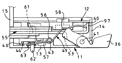
Shown in the Figures is a lock of the invention, which in the illustrated
embodiment is rim mounted, i.e. as shown in Figure 23, is intended to be
mounted at one side and partly at one front edge surface of a wing such as a
conventionally hinged door 10 which has an associated frame and staple (not
shown) so that the door can be moved between an open position and a closed
position in which it is locked by a bolt of the lock, such bolt being
described
hereinafter.
The lock has a metal casing made up of a main body part 11, in the general
form of a square box structure having one side open, and a closure part 12 in
the form of a flat square metal plate. The plate has respective holes at or
CA 02373124 2001-11-05
WO 01/69019 PCT/GBOI/00741
-6-
adjacent each of its four corners for fixing screws passing into respective
threaded bores in bosses formed with the body part 11, to secure part 12 in
place inwards of the plane of the outer free edge surface of the part 11, and
to complete the lock casing with the assembled components therein concealed
from view.
As mentioned, the main body part 11 is in the form of a square box-structure
and Figure 23 shows a side wall 13 integrally formed with an end wall 14
and a front wall 15 which is extended from the side wall 13 further than the
end wall 14 to form a forend of the lock, with the extension part of the wall
15 being secured to a front edge surface of the door 10 as shown in Figure
23, with the free edge surface of the end wall 14 engaging against the inner
side of the door, in use, again as shown in Figure 23. The main body part 11
is completed by a bottom wall 16, and a parallel top wall 17 shown in
Figures 17 and 18.
The extended part of the front wall 15 is formed with a spaced pair of
countersunk holes adjacent its upper and lower edges respectively, one of
which 18, is shown in Figure 23, these countersunk holes receiving
corresponding screws, such as screw 19 shown in Figure 23, for securing
this extension of the front wall 15 in a corresponding depth rebate in the
front
edge surface of the door 10. In the front wall 15, at a position just inward
of
the plane defined at the open side of part 11, are a pair of spaced
countersunk
holes, one of which 20 is shown in Figure 23. At substantially the same
level from the side wall 13 as the countersunk holes 20 is provided on the
interior of the end wall 14 an integral lug 21 which has a circular-section
hole
22 therethrough, the plate 12 having a cut-out to accommodate the lug 21.
CA 02373124 2001-11-05
WO 01/69019 PCT/GBOI/00741
-7-
The outer surface of the lug is spaced from the outer free edge surface of the
body part 11 by the thickness of a flat mounting plate 12a. This lug 21 is
centrally disposed along the end wall 14, and the plate 12a has a tapped hole
23 adjacent one of its edges centrally along the length thereof, so that, as
shown in Figure 23, with the plate 12a in place at the 'open' side of the main
body part 11, the plate 12a can rest on the outer surface of the lug 21, at a
position spaced from part 12, so as to lie flush at said 'open' side of the
body
part 11, with the hole 23 aligned with the hole 22 through the lug.
Moreover, at its edge surface opposite to its edge surface adjacent which the
hole 23 is provided, there are two integral bent down tags, one of which, 24,
is shown in Figure 23. Each tag extends through a slot in part 12, and has a
tapped hole therethrough this being shown as 25 for tag 24. With the plate
12a arranged, as described, flush at the outer 'open' side of the body part
11,
the holes through the respective tags are aligned with the countersunk holes
20 to receive fixing screws, one of which, 26, is shown in Figure 23. In use,
as shown in Figure 23, a screw 27, captive in the hole 22 in the lug, has its
shank engaged in the aligned tapped hole 23 in the plate 12a, with its free
end
received in a recess in the side surface of the door. Accordingly in this way
the completed casing, comprising the main body part 11 and part 12, is
secured to the mounting plate 12a, and by way of the screws 19 the
completed casing is also secured to part of the front edge surface of the
door.
The fixing of the plate 12a to part 11 is particularly convenient as compared
to prior art arrangements where the equivalent component is often a
complicated pressing with tags, slots and the like for securement to the lock
case. The plate 12a has two countersunk fixing holes therein, one spaced
above the other, for wood screws to fix it to the side of the door. One hole
12b is shown in Figure 23. The fixing of the screw 27 forms the subject of
CA 02373124 2006-10-27
WO 01/69019 PCT/GB01/00741
-8-
WO 01/69017.
Additionally as shown in Figure 23, the plate 12a has a lock cylinder and
plug assembly 28 secured thereto. The assembly is positioned on the plate
12a centrally over a circular hole (not shown) in the plate 12a, with
respective projections from the end of the cylinder at respective opposite
sides of said hole in the plate 12a, extending into correspondingly shaped
openings respectively in the plate 12a. To secure the assembly 28 in this
located position on the plate 12a, the plate has a pair of spaced aligned
holes
29 therethrough at opposite sides of the hole in the plate 12a at which the
assembly is centred, and screws 30 are respectively engaged in the holes 29,
with the shanks of said screws, extending into respective threaded bores 31 in
the cylinder of the assembly 28.
In use, as shown in Figure 23, the completed casing is secured to the door as
showd, with the assembly 28 received in a circular-section opening through
the door, the end of the assembly projecting from the other side of the door
and having fixed therearound a rose 32 or equivalent member. The rose can
have a pair of rearwardly directed bosses, arranged diametrically at the top
and bottom of the assembly 28, and received in respective bores in the door,
and these bosses can be aligned with respective bolts, one of which is shown
in Figure 23 by the numeral 33, which extend through respective holes in the
plate 12a, with the shanks of the bolts extending through the thickness of the
door 10. In one arrangement the threaded ends of these bolts can be engaged
in open threaded ends respectively of the rearwardly extending bosses of the
CA 02373124 2001-11-05
WO 01/69019 PCT/GBOI/00741
-9-
rose 32 so as tightly to secure the rose to the outer surface of the door as
shown in Figure 23. With the arrangement described, therefore, and as
shown in Figure 23, the lock casing is securely secured to one side of the
door with its lock cylinder and plug assembly 28 secured through the door
and accessible for operation at the opposite side thereof. Schematically
shown in Figure 31 is a plug 28a and operating bar 28b of assembly 28.
A central edge part of the side wall 13 is provided with a rectangular opening
34 schematically as identified in Figure 23, and a communicating similar
rectangular opening 35 is provided in the adjoining edge part of end wall 14.
At opposite ends of the opening 34 the interior surface of side wall 13 is
provided with respective concave semi-cylindrical bearing surfaces for
pivotally mounting a handle 36 which extends through the openings 34 and
35, as will be described. The bearing surfaces 34a are identified in Figures
24, 26 and 30.
Disposed centrally in the side wall 13 and spaced a little way inwardly of the
inner edge of the opening 34, is an oval hole 37 in which is fitted a housing
38 for a lock cylinder 39 and its associated plug 40 as shown in Figures 19
and 25. This housing 38 is in the form of a metal casting, e.g. of zinc based
alloy, and also includes a pair of parallel spaced arms 38a which have
respective concave semi-cylindrical bearing surfaces 38b defined therein as
shown in Figures 24, 26 and 29. The bearing surfaces 38b mate with the
corresponding bearing surfaces 34a to form a pair of spaced full bearings for
a pivot rod 41 which is located in a part circular channel 42 (Figures 19A,
21, 22 and 23) adjacent an inner edge of the handle 36 so as to allow pivoting
of the handle 36 relative to the casing. Respective opposite end portions of
CA 02373124 2001-11-05
WO 01/69019 PCT/GBOI/00741
-10-
the rod 41 pass through respective opposite ends of the handle which close
the channel 42, and extend outside of said handle ends into said full bearings
respectively. Full pivoting of the handle, as shown in Figures 5 and 23, is
required to allow access through a cut-out 36a in the end of the handle, and
through openings 34, 35, for a screwdriver shank 27a, to enable it to engage
the screw 27 both on assembly of the lock casing to the door, or for removal.
The housing 38 also provides, adjacent said spaced arms thereof, respective
fixing holes 38c therethrough, these holes being aligned with respective
internally threaded bosses 13a upstanding from the inner surface of the side
wall 13. By the use of fixing screws, the housing 38 is thereby secured to
said side wall of the casing. This side wall has two holes 13c,13d
therethrough at respective opposite sides of the part of the housing which
extends outwardly from said side wall 13, these holes being on a diameter
through the centre of the lock cylinder 39 and its associated plug 40. The
part of the housing 38 within the casing is provided with one hole 38d aligned
with the hole 13c in the side wall 13 and also a cut-away 38e which is aligned
with said other 13d of said diametrically aligned holes in the side wall 13.
The shanks of respective headed fixing screws 38h (Figures 19B and 19C)
are received through said holes 13c, 13d in the side wall 13, with the heads
received in said hole 38d and cut-away 38e respectively. The respective
threaded ends of these fixing screws are threadedly received in blind bores in
the inner surface of a rose 110 which is fitted around the part of the housing
38 projecting outwardly of the casing, this rose being pulled by said fixing
screws against the outer surface of the side wall 13 so as to conceal from
view, and to prevent access to, a grub screw hole 38f with associated grub
screw 38g, extending through the housing 38 at the exterior of the casing,
CA 02373124 2006-10-27
-11-
this grub screw engaging in a recess in the outer side of the cylinder 39,
thereby to secure the cylinder, with its associated rotatable plug therein, to
the housing 38. The respective posi-drive heads of these fixing screws
extending through the casing part 11 to secure the rose in place are arranged
to be uncovered and easily accessible within the casing part 11 when the
assembly of casing part 11 and closure part 12 is removed from the plate 12a
on the door in use, and with the bolt of the lock held retracted, without
having to remove components of the lock from the casing part 11, thereby
making cylinder removal and replacement much easier than with known
arrangements. The plate 12 has holes 12c therein aligned with these fixing
screws respectively. Once the casing part 11 is removed from the door, all
that is required is an undoing of said uncovered fixing screws, the heads of
which move into previously 'empty' parts of hole 38d and cut-away 38e, to
release the rose 110, thereby uncovering the grub screw 38g. This is then
undone, allowing the cylinder 39 and plug 40 to be changed at the outside of
the casing part 11. The grub screw is then retightened, the rose replaced and
the fixing screws tightened to secure the rose to the surface of side wall 13.
This feature forms the subject of WO 01/69016. On assembly the rose 110 can
firstly
be secured in place by screws 38h and the housing 38 secured in place
thereafter.
The structure of the housing 38 within the casing, provides four further
functions. Firstly, it has two further spaced arms 138a defming respective
concave semi-cylindrical bearing surfaces 138b, the arms and the bearing
surfaces being shown in Figures 24 to 29. The arms 138b extend away from
CA 02373124 2001-11-05
WO 01/69019 PCT/GBOI/00741
-12-
the end wall 14 and the surfaces 138b are directed towards the interior
surface of the side wall 13 where said bearing surfaces 138b mate with
corresponding respective concave semi-cylindrical bearing surfaces 13b
formed on projections upstanding from the interior surface of the side wall
13. This pair of completed spaced bearings act as a pivoting arrangement for
a rod 43 of a deadlock element 44 shown best in Figures 1 to 5, Figures 7 to
12, and Figures 25 and 26.
As shown in these Figures, the deadlock element has a rectangular body part
45 extending away from the rod 43, the part 45 having a downturned nose 46
at its end remote from the rod. At the longer side of the body part 45 facing
the top wall 17, the body part has a U-shaped projection 47 which is open
upwardly and outwardly. The lower interior surface of the projection 47 is
substantially at the level of the underside of the body part 45, but at the
location of this projection 47, the side of the body part has its lower
portion
recessed, as shown at 48, so as to receive, as will be described, a straight
end
part of a spring-like connecting member 49 which links the handle 36 to said
deadlock element 44. A second function provided by the housing 38 is a
provision of a pair of upstanding surfaces 138c which defme between them a
guide slot 138d for a further part 50 of the spring-like connecting member 49
which extends to co-act with the handle 36. As shown in Figures 1 to 5, the
handle, at its side adjacent the top wall 17 has an arm 51 extending from said
channel 42, this arm defining a nose part 52. At its inner side, spaced
slightly downwardly from the top of the nose part 52, as viewed with the
orientation of the nose part shown in Figures 1 to 3, is a further, smaller
nose
part 53, the parts 52 and 53 being spaced by a section defining a groove 54.
This groove is to receive said further part 50 of the spring-like connecting
CA 02373124 2001-11-05
WO 01/69019 PCT/GB01/00741
-13-
member 49, as shown in Figures 1 to 5, whilst the further nose part 53 is to
engage an end of a bolt 55 of the lock, as will be described hereinafter.
As shown in Figures 1 to 5, the connecting member 49, which is of spring
steel, has a central coiled part 56, which is received on the rod 43 which
acts
as the pivot for the deadlock element 44. At the end of the coiled part 56
remote from the top wall 17, the member is formed with a straight part 57,
lying in a plane parallel to the walls 16 and 17, this having its end turned
through 90 to provide the previously mentioned straight part which extends
into the recessed portion 48 of the body part 45 of the deadlock element 44 as
shown in Figures 1 to 5. At the other end of the coiled part 56, the further
part 50 extends away from the side wall 13, through the guide slot 138d, and
into the interior of the casing where it is formed with a concave kink 58 and
then a convex kink 59 before terminating in a slightly arcuate end portion 60.
This further part 50 of the connecting member 49 lies in a plane parallel to
the top wall 17 which is in the same plane as the groove 54. As will be
explained further for the lock, in use, it can be seen from Figures 1 and 2
that with the bolt in its fully retracted or partly extended position the kink
58
and kink 59 are spaced clear of said groove 54. However, in the fully
extended position of the bolt 55 shown in Figure 3, as the deadlock element
44 pivots into the interior of the casing, the kink 58 moves into said groove.
If from this position the handle 36 is now pivoted to retract the bolt 55, it
can
be seen that this part of the connecting member 49 is lifted at the kink 59,
such that the straight part 57 of member 49 acts to move deadlock element 44
pivotally back to its Figure 1 position. Accordingly the bolt is no longer
prevented from moving inwardly by element 44 and is retracted as the handle
is pivoted to its Figure 5 position.
CA 02373124 2006-10-27
WO 01/69019 PCT/GBOI/00741
=14-
Figure 5 shows the position reached when the handle is in its fully pivoted
position relative to the casing so that its nose part 52 engages the end wall
14, with the end portion 60 of the connecting member 49 being raised in the
groove 54 to its innermost position in the casing where it lies adjacent the
inner surface of the closure part 12. From these Figures it will be noted that
from the inner side of the body part 45 .there is a cylindrical projection 61
with a hemi-spherical head, whilst on the same axis, but at the opposite side
there extends an identical but smaller diameter projection 62. This*
projection
62 is movable through a slot 63 in the side wall 13, and the inner surface of
the side wall 13 is formed with a circular section pocket 64 around the slot
63, with a coiled compression spring 65 being received around the projection
62 and having its one end located in said pocket. In this way, the deadlock
element 44 is biased to pivot inwardly into the casing, to the position shown
in Figure 3, with the projection 62 acting as an indicator at the exterior of
the
side wall 13 of the lock to indicate whether or not the bolt 55 is deadlocked.
As explained, pivoting of the handle from its Figure 3 to its Figure 5
position
causes, by way of the intermediary of the connecting meniber 49 overcoming
the force of spring 65, pivoting. of the deadlock element 44 to its Figure 1
position, and accordingly, as will be explained, retraction of the bolt 55.
The
feature of the connecting member forms the subject of WO 01/69018.
The housing 38 further provides a pair of spaced inwardly directed arms 66
(Figures 16 to 18 and 28) and upstanding from the inner surface of the side
wall 13 are a pair of spaced parallel guide walls 67 extending normal to the
CA 02373124 2001-11-05
WO 01/69019 PCT/GBOI/00741
-15-
top and bottom walls 16,17, these guide walls 67 lying slightly inwards of the
inner surface of the front wall 15, as shown schematically in Figure 16.
Each guide wall is interrupted by a generally rectangular slot 67a extending
inwards from the outer free edge surface of the guide wall, the two slots
being aligned with each other, and also with the opening defined between the
two arms 66. Moreover, the front wall of the casing is formed with a
rectangular slot 68 which is in the same plane as, and thus aligned with, the
aligned slots of the guide walls 67 and the opening between the arms 66.
This arrangement is to accommodate a spring loaded bolt release member 69
shown in Figures 16 to 18. The member 69 is of elongate form having a tail
part 70, which is straight with an upturned end, a coiled compression spring
71 being disposed around the straight section of part 70. The part 70 is
arranged to engage in the opening between the arms 66, with one end of the
coiled compression spring engaging against the respective sides of the arms
facing the front wall 15. The other end of the spring abuts a main body part
72 of the member 69, this being arranged to slide across the guide walls 67
by being received in the slots which interrupt said guide walls as described.
At the free end of the body part 72 is a chamfered nose part 73 which is
arranged slidingly to extend through the slot 68 as a close sliding fit, as
best
shown in Figures 16 and 18 which represent the fully extended and fully
retracted positions respectively of the member 69. Lying between the guide
walls 67 on a part cylindrical bearing surface defined between said guide
walls 67, is a cylindrical bolt holding member 74 which is arranged
automatically to engage with the bolt 55 in its normally fully retracted
positions shown in Figures 1 and 5. The member 74 is biased by a coil
spring 75 received between the top wall 17 and an end of the member 74 to
move it away from the wall 17. Along its length, the member 74 is provided
CA 02373124 2001-11-05
WO 01/69019 PCT/GBOI/00741
-16-
with a transverse recess 76 in which is received the main body part 72 of the
bolt release member 69. This main body part 72 is of two thicknesses joined
by a chamfered surface 77 which, in this embodiment, faces the top wall 17
as shown in Figures 17 and 18. The position of this chamfered surface 77
along the length of the bolt release member 69 is such that when the member
69 is in its fully extended position shown in Figure 16, the thinner portion
of
the main body part 72 is within the recess 76, adjacent the side of the recess
nearest the top wall 17. However, as the member 69 is extended into the
casing, the chamfered surface 77 engages the edge of the recess 76 nearest
the top wall 17, so that as the linear inwards movement of the bolt release
member 69 continues, this chamfered surface forces the member 74 in a
direction towards the top wall 17 against the bias of its spring 75. At its
opposite end to that at which the spring 75 abuts, the member 74 has a pin 78
adapted to engage in a recess 79 defined in one longitudinal side of the bolt
55.
Accordingly it can now be appreciated from Figures 17 and 18 how this pin
78 of the member 74 is spring biased to engage in said recess 79, and thus to
hold the bolt in its normally retracted state with the bolt release member 69
spring loaded to its fully extended position. However, as will be described,
when the door 10 is closed, the member 69 is automatically forced into the
casing against its spring bias, by engagement with the staple at the
doorframe, so that, as the member 69 moves to its Figure 18 position, its
chamfered surface 77 moves the member 74 against its spring bias to release
the pin 78 from the recess 79 of the bolt 55 which then automatically moves
to its extended position under the bias of a coiled compression spring (not
shown) which is received in a longitudinal guide 213 which is parallel to and
CA 02373124 2001-11-05
WO 01/69019 PCT/GB01/00741
-17-
spaced inwardly of the bottom wall 16, this guide extending upwardly from
the side wall 13 and extending to the inner surface of the front wall 15. The
bolt 55 is provided with a peg extending from its side facing the side wall
13,
this peg extending into the guide and thus serving to compress the spring
therein when the bolt is moved to its normally fully retracted position and
held by member 74, release of the member 74 normally thus allowing this
spring to extend in its guide, thereby moving the peg along said guide and
causing extension of the bolt.
A final function provided by the housing 38 is that, in one embodiment, it is
extended inwardly of its portion receiving the lock cylinder 39 and associated
plug 40 to house a cylindrical component 80 having a radial blocking lug 81
extending from the outer surface thereof. If the housing 38 provides this
function, then it receives part of the length of the component 80 within a
cylindrical housing part which is provided with an arcuate cut-away portion
therein which extends around approximately 100 of arc to allow for
movement of the blocking lug 81 between its two extreme positions at
opposite ends of said cut-away portion, whilst projecting outwardly from this
portion of the housing 38 in which the component can rotate. For clarity,
this inwardly extended part of the housing 38 is not shown in Figure 19, but
is shown in Figure 28, the cut-away being indicated at 181.
The component 80 has the lug 81 extending from its outer surface adjacent
one end thereof, this end being the one which is adjacent the inner end of the
plug 40 as shown in Figure 19. The end surface of the plug is recessed
inwardly of the end surface of the cylinder, but with a projection 82
extending beyond the end of said cylinder. The end of the component 80 is
CA 02373124 2001-11-05
WO 01/69019 PCT/GBO1/00741
-18-
formed with a reduced diameter part 83 which is sized to fit within the recess
defined at the end of the cylinder, so that this end part 83 is received in
engagement with the end of the plug. However this end part 83 of
component 80 does itself have a recess 84 therein extending over
approximately 60 of arc, with the projection 82 being received in said
recess, so that when the plug is rotated by operation of a key in the plug 40
at
the inside of the door this projection 82 will rotate the component 80 under
some circumstances where the projection is in engagement with one of the
side surfaces of the recess 84, as will be described. The provision of the
recess 84 does however provide for lost motion between the plug and the
component 80 so that the plug can be brought back to its position in which
the key can be removed from the lock cylinder, whilst leaving the component
80 in its rotated position.
The opposite end of the component 80 has a generally central circular-section
bore therein, but within said bore are a pair of diametrically opposed
projections 80a (Figures 32A and 32B) of V-shape, with the respective apices
of the two shaped projections being spaced apart but facing one another. The
side faces of each projection are flat, and arranged so that the operating bar
28b of the plug 28a of the assembly 28 is received in this bore in such a
manner that key operation of the assembly 28 from the exterior of the door
will cause the bar to engage one side of one of the projections on one of its
sides and one side of the other projection at its other side so as to turn
this
component between its opposite extreme positions (Figure 32B). The annular
form and spacing of the projections means that, again, there is lost motion
between the locking bar, i.e. the cylinder and plug assembly 28 and the
component 80, it being appreciated that in one direction of rotation the bar
CA 02373124 2001-11-05
WO 01/69019 PCT/GBOI/00741
-19-
will engage one flat surface of one projection and one flat surface of the
other
projection, whilst in the other direction of rotation the bar will engage
respective opposite surfaces of said projections to turn the component 80 in
the other direction, again the lost motion allowing the plug and cylinder
assembly 28 to be moved to a position (Figure 32A) relative to the
component 80 where the key can be removed. Figures 20 to 22 and Figure
28 show schematically two small angularly spaced apart semi-circular section
recesses 85,86 in the interior surface of the extended part of the housing 38
in which part of the component 80 is received, and each recess selectively
mates with a small bore 87 in the exterior surface of the component 80
angularly spaced therearound from the lug 81. A small spring is received in
said bore 87 and at the end of this is a small ball. In this way the ball is
spring biased across the interface between the component 80 and each recess
85,86 as relative rotation takes place between the component 80 and the
housing 38. In other words in each of its extreme positions, the component
80 is held substantially firmly in place, against inadvertent rotation, by the
spring loaded ball.
Figure 20 shows that the handle is provided, adjacent its channel 42 with a
centrally disposed projection 88 which has a flat surface which faces the
closure part 12 when the handle is in its rest position shown in Figure 19. At
its one side, this projection is provided with an upstanding wall 89 which
acts
as a stop. The position of this projection relative to the component 80 is
such
that under normal conditions the blocking lug 81 is in the position shown in
Figure 21 or Figure 22 where it is clear of the projection 88 so that the
handle can be pivoted as previously described in relation to Figures 4 and 5
to retract the bolt 55. If, however, as briefly described above, the
CA 02373124 2001-11-05
WO 01/69019 PCT/GB01/00741
-20-
component 80 is moved angularly from its extreme position shown in Figures
21 and 22 to its other extreme position shown in Figure 20, the blocking lug
81 will lie over the flat surface of the projection 88, if the handle is in
its rest
position, the lug 81 engaging against the stop wall 89 as shown in Figure 20.
In this position pivoting of the handle is prevented by the blocking lug 81.
In
relation to the handle 36, it is to be noted that a coiled torsion spring (not
shown) is received around the pivot rod 41, with one end of the spring
engaging against the end wall 14 and the other end engaging against the
channel 42 so as to bias the handle to its rest position shown in Figure 19.
As shown in Figures 13 to 15, and also in Figures 1 to 5, the bolt 55 is of
generally laminar construction being made up generally of a series of
interconnected plates all defming a generally rectangular leading end part
which extends into and out of the casing through a correspondingly shaped
opening 91 in the front wall 15 of the casing. Defined through the centre of
the bolt at a position inwards of said leading end part is a slot 92 in which
is
received the cylindrical projection 61 as shown in Figures 1 to 5. Whilst the
two innermost and also the two outermost plates 90 defined relative to the
side wall 13 terminate at the end of or shortly beyond the end of the leading
end part of the bolt, the middle plate, denoted by the numeral 93, is of
greater extent from said leading end part and defines two arm portions 94,95
at opposite sides of the slot 92 which is extended to the end of the plate 93
remote from said leading end part. At the free end of the arm portion 94,
part of the plate 93 is turned through 90 to form a foot 96 which is directed
towards the plate 12. Similarly the free end of the arm portion 95 is also
turned through 900 to provide a foot 97 again directed towards the plate 12.
As will be appreciated from Figures 1 to 5 and 13 to 15, the foot 97 is for
CA 02373124 2001-11-05
WO 01/69019 PCT/GBOI/00741
-21-
engagement by the further nose part 53 to retract the bolt from its extended
position, whilst the foot 97 is for engagement by a driving surface 98 of a
cam 99 to be described with reference to Figures 6 to 12.
Figure 3 shows that with the bolt fully extended and the handle in its rest
position, the further nose part 53 is spaced from the foot 97 of the bolt.
This
is to allow for the movement of the further part 50 of the connecting member
49 to its Figure 4 position by the pivoting of the handle, thereby moving the
deadlock element 44 clear of the bolt, before the further nose part 53 engages
foot 97 to retract the bolt. In this way, retraction of the bolt is unhindered
by
the element 44. Similarly Figure 6 shows that the surface 98 of the cam is
spaced from the bolt foot 96 when the bolt is fully extended and the cam is in
its rest position. This allows initial cam angular movement by a key, as will
be described, to move the element 44 clear of the bolt (Figure 11) before the
surface 98 engages the foot 96 to retract the bolt. Thus again retraction of
the bolt is unhindered by the element 44.
The arm portion 94 has a hole 100 therethrough adjacent the foot 96, this
hole 100 aligning, in a retracted position of the bolt, with one of the holes
12c and the holes 13b and 38d to provide access for a screwdriver shaft to
one of the fixing screws 38h. In an outer edge of the other arm portion 95 is
formed a circular section recess 101 which again, when the bolt is in said
retracted position, aligns with the other of the holes 12c and the hole 13c
and
cut-away 38e, to allow screwdriver access to the other of the fixing screws
38h. In this manner with the bolt in a retracted position, and, as previously
described, the assembly of lock casing part 11 and plate 12 removed from the
door, the respective heads of both of these screws 38h holding the rose 110
CA 02373124 2006-10-27
-22-
are then accessible to allow the screws to be undone, in order to allow for
removal of the rose, and easy replacement of the lock cylinder 39 and
associated plug 40,_ this aspect of the invention, as mentioned, forming the
subject of WO 01/69016. It can be arranged that the retracted position of the
bolt for
access to screws 38h is the one when it is held by the member 74 in Figure 17.
In an outer edge of the arm portion 94 there is provided a cut-out 102 to
allow for assembly of the spring which biases the bolt outwardly, into its
guide 213. Finally a circular hole 103 is provided in the arm portion 94
adjacent its end thereof nearest the leading end part of the bolt, but clear
of
the other four plates 90 of the bolt. In conjunction with this hole 103, there
is provided in the side wall 13 a circular section through opening 104 which
at the inside surface of the side wall is provided through a boss 105.
Extending through said opening 104 and into said boss is a snib 106 for
retaining the bolt in its normal fully retracted position as shown in Figures
13
to 15. The sftib 106 has a head 107 which is visible from the exterior of the
side wall 13 and which allows the snib to be manually operable from inside
of the door to which the lock is fitted, in use. From the head 107, the snib
is
stepped downwardly twice to define a central reduced diameter part 108 and
an end further reduced diameter part 109, all the parts being about a common
central axis. A circlip 110 is engaged in a groove of the snib at the junction
between the parts 108 and 109, and a coil spring 111 is received around the
central part 108, with its one end engaged against an underside of the head
107. The snib is fitted at the opening 104 and boss 105 as shown in Figures
13 to 15, so that the other end of the spring is engaged against a step at the
CA 02373124 2001-11-05
WO 01/69019 PCT/GB01/00741
-23-
inner part of the boss so that the snib is normally biased outwardly to its
Figure 13 position where the circlip 110 acts as a stop against the innermost
surface of the boss to hold the snib in place at the casing.
Although the hole 103 is of a size to receive the part 109 of the snib
therein,
it can be seen from Figure 13 that in its normal fully retracted state, i.e.
with
the nose part 52 of the handle 36 in engagement with the end wall 14, this
hole 103 is out of alignment with the part 109 of the snib. However it will
also be noticed that the foot 97 has itself not yet reached the inner surface
of
the end wall 14. Accordingly in order to operate the snib, it is first
necessary
to push the bolt rearwardly from its Figure 13 position by applying pressure
to its leading end part. This moves the foot 97 into engagement with the
inner surface of the end wall 14 as shown in Figure 14, thereby aligning the
hole 103 with the part 109 of the snib, allowing the snib to be moved into
said hole against its spring bias. Once the part 109 of the snib has been
moved into the hole 103, the inwards pressure on the end of the bolt can then
be released, and the spring acting on the bolt will move it back to its normal
fully retracted position shown in Figure 15, with the part 109 of the snib
retained in the hole 103, which, it will be appreciated, is somewhat oversized
in relation to the diameter of the part 109 so as to allow for said movement
of
the bolt between its Figures 14 and 15 positions respectively. It can be seen
that, if required, the free end of the part 109 can be provided with a narrow
flange to define, with the circlip 110, a neck held in hole 103. Once the snib
has engaged the bolt as shown in Figure 15, release of the snib can only be
effected by again applying inwards pressure to the end of the bolt, thereby
releasing engagement of the bolt at the edge of the hole 103 on the part 109.
The spring 111 then automatically moves the released snib back to its Figure
CA 02373124 2001-11-05
WO 01/69019 PCT/GB01/00741
-24-
13 position and the greater projection of the head 107 at the outside of the
side wall 13 indicates that the snib is no longer engaged, so that in closing
the
door, the bolt will automatically extend as described herein above. Although
as described and shown, the snib holds the bolt in its Figure 17 retracted
position, the snib could alternatively be arranged to hold the bolt in a
position
between the positions of the bolt in Figures 13 and 15 respectively.
Accordingly the hole 100 and recess 101 would be re-positioned to allow
access to screws 38h, although with posi-drive screw heads a screwdriver
shank at an angle thereto might still be able to undo the screws. The feature
of the snib to lock the retracted bolt against release on closing the door
forms
the subject of the present application.
Finally with regard to the components of the lock, reference is made to
Figures 6 to 12 which show the cam 99, the driving surface 98 of which, as
mentioned previously, acts, in operation, on the foot 96 to retract the bolt
55.
As will be described, the handle operates, in use, from the inside of the door
to retract the bolt by way of the further nose part 53 acting on the foot 97,
whereas from the outside of the door key operation at the cylinder and plug
assembly 28 moves this cam 99 and thus retracts the bolt by way of the
driving surface 98 engaging the foot 96. In its rest position, shown in
Figures 6, 8 and 9, a side surface thereof engages a stop 99a in the form of a
lug or equivalent projecting inwardly from closure part 12 to prevent
anticlockwise movement of the cam (as viewed in Figure 6) from its rest
position.
The cam 99 is provided on its one side with a hollow boss 112 (Figure 19A)
which is rotatably received on the end of the component 80 which has therein
CA 02373124 2001-11-05
WO 01/69019 PCT/GBOI/00741
-25-
the bore containing said V-shaped projections. At the other side of the cam
is an upstanding boss 113 which has the same centre as the boss 112. A slot
114 for a locking bar of the cylinder and plug assembly 28 extends through
the boss 113 and into the interior of the hollow boss 112, rotation of the
locking bar being effected upon key rotation of the plug of the lock cylinder
and plug assembly 28 to rotate the component 80 as described, with there
being lost motion between the cam 99 and the component 80. As shown in
Figures 6 to 12, the surface of the cam at the side at which the boss 112 is
provided is formed from an edge surface 115 disposed at approximately 90
around the cam from the surface 98, with a first flat surface 116 and a second
longer flat surface 117, these two flat surfaces being joined by a ramp
section
118. Figures 6 and 7 show the arrangement where the bolt 55 is fully
extended and deadlocked in this position by the nose 46 engaging the inner
end of the plate 90 immediately adjacent the middle plate 93 at the side
thereof facing the side wall 13. As shown in Figures 1 to 5 and 13 to 15, this
plate which is in engagement with the middle plate 93, extends further inward
than the outer plate of this side of the bolt which faces the side wall 13 so
that, as shown in Figure 2, the nose 46 will also deadlock the bolt in its
partly extended position, the nose then engaging the inner end of said
outermost plate at this side of the bolt.
Accordingly as shown in Figure 7, corresponding to the arrangement of
Figure 3, the bolt is held in its fully extended position with the hemi-
spherical head of the projection 61 being in juxtaposition with the flat
surface
116. If key operation of the lock is now effected from the exterior of the
door, the cam 99 will rotate as described and retract the bolt. Figure 8
shows the position where the bolt is fully retracted and held in this position
CA 02373124 2001-11-05
WO 01/69019 PCT/GBOI/00741
-26-
by the member 74, the cam being returned by key rotation to its position
shown in Figure 8, Figure 9 showing how the hemispherical head of the
projection 61 is now spaced clear of the flat surface 116 as the deadlock
element is now in its Figure 1 position. Figure 11 shows how the projection
61 is depressed as the cam rotates, with the head of the projection 61 being
forced against its spring bias as its head engages the ramp section 118, this
movement against its spring releasing the deadlocking of the bolt which can
then be retracted by virtue of the driving surface 98 of the cam 99 engaging
the arm portion 96 of the bolt. Figure 12 shows the relative positions of the
cam and the deadlock element in the position where the cam engages the arm
portion 96 before the cam is moved by key rotation to return to its Figure 8
position. With the bolt held fully retracted, key rotation will return the cam
from its dashed Figure 10 position of engagement with foot 98 back to its
Figure 1 position, where the cam engages its stop 99a.
Operation of the lock, in use, will now be described.
With the lock fitted to the door 10 as shown in Figure 23, the lock cylinder
and plug assembly 28 is operable by a key from the outside of the door, the
lock cylinder 39 and associated plug 40 of Figure 19 being operable from the
inside of the door by use of the same key. Conveniently each plug and
cylinder assembly, and the key, may be of the form described and claimed in
our pending published European Patent Application No. 0892130.
Normally, with the door 10 closed, i.e. received in its associated frame, the
bolt 55 is in its fully extended position, for example as shown in Figure 3,
the leading end part of the bolt projecting from the front wall 15 being
CA 02373124 2001-11-05
WO 01/69019 PCT/GBOI/00741
-27-
received in an associated keeper of any conventional form secured at or to the
frame. In this state, the deadlock element 44 is in the position shown in
Figure 3 where it deadlocks the bolt 55, as described, by acting as an
abutment with the plate 90 of the bolt attached to the outer side of the plate
93. In this deadlocked state, the projection 62 is fully received in the case,
and this provides a visual indication at the inside of the door that the
deadlocking is in operation. Moreover in this state, the handle 36 is in its
rest position as shown in Figure 3, the cam 99 is in its rest position as
shown
in Figure 6, the snib 106 is in its rest position shown in Figure 13, and the
bolt release member 69 is in its retracted position shown in Figure 18, being
held against its spring bias by the engagement of the nose part 73 with the
surface of the staple. As can be seen from Figure 18, with the bolt release
member in this position, the bolt holding member 74 is held by it clear of the
adjacent side surface of the bolt.
In this deadlocked state, the door can be opened from the exterior by the use
of the key for the lock in the assembly 28. If the key is inserted into the
plug
of the assembly 28 and turned clockwise, as viewed in Figure 20, the locking
bar of the assembly 28 received in the slot 114 in the cam 99 will cause the
cam to move angularly in a clockwise direction as viewed in Figures 6 to 10.
Firstly the driving surface 98 of the cam will move towards the foot 96, and
at the same time the ramp section 118 of the cam will engage the head of the
projection 61 so as to begin moving it to release the deadlocking on the bolt,
so that when the surface 98 engages the foot 96, it can begin to retract the
bolt into the casing as the projection 61 has now been engaged by the second
longer flat surface 117 of the cam, as shown in Figure 11, with the deadlock
element 44 now being clear of the outer plate 90 of the bolt, as shown in
CA 02373124 2001-11-05
WO 01/69019 PCT/GBOI/00741
-28-
Figure 11. The cam is then moved angularly by the locking bar until the bolt
is in its normally fully retracted state, shown in dashed in Figure 10, and as
shown in Figure 12 with the cam moved angularly to its extreme position.
In this state, however, unless the door is now opened, the bolt is not held
retracted, given that the bolt release member 69 is still in its Figure 18
position, preventing the bolt holding member 74 engaging the retracted bolt.
Accordingly once the bolt is fully retracted, it is necessary to open the
door,
whereupon the bolt release member 69 is released from its engagement with
the frame and, under its spring bias, slides to its Figure 17 position where
its
nose part 73 extends from the front face of the lock. This sliding allows the
bolt holding member 74 to move under its spring bias, to its Figure 17
position where its pin 78 engages in the recess 79 in the side of the bolt,
thereby holding the bolt in its retracted state. The key, and thus the plug of
the assembly 28 can now be returned to its rest/key insertion position and the
key removed. This return movement of the key brings the cam 99 from its
one extreme position, shown in Figure 12 and in dashed in Figure 10, to its
other extreme or rest position shown in Figure 8, with the bolt retracted, the
deadlock element 44 being in the position shown in Figure 1 merely in
engagement with one side of the bolt, with its projection 62 projecting from
the exterior surface of side wall 13 to indicate that the bolt is not
deadlocked.
Once at the inside of the door, a user can then close the door, which action
automatically 'throws' the bolt, thereby locking the door. This is
accomplished merely by closing the door from the inside, since this will
cause engagement of the nose part 73 of the bolt release member 69 with the
staple, thereby forcing this member 69 into the lock casing from its Figure 17
CA 02373124 2001-11-05
WO 01/69019 PCT/GBOI/00741
-29-
position to its Figure 18 position, this resulting in withdrawal of the bolt
holding member 74. As a consequence the bolt is automatically extended
under the force of its biasing spring so that it is shot out of the casing to
its
Figure 3 position, with the deadlock element 44 operating automatically as
shown in Figures 1 to 3 again to deadlock the bolt.
Thereafter to open the door from the inside, it is merely necessary to pivot
the lever 36 at the inside of the door from its rest position shown in Figures
1
to 3 to its fully pivoted position shown in Figure 5. This pivoting of the
lever is transmitted via the connecting member 49 to the deadlock element 44
so as to move this firstly to its Figure 4 position, where it no longer
deadlocks the bolt, and then to its Figure 5 position where the bolt is fully
retracted into the casing by virtue of the further nose part 53 of the handle
engaging the foot 97 of plate 93 of the bolt as shown in Figures 4 and 5, this
retraction of the bolt taking place against its biasing spring, with pivoting
of
the handle also taking place against its own biasing spring. Once the Figure
position is reached, it is again necessary to open the door in order to retain
the bolt in its retracted position by means of the bolt holding member 74.
Accordingly, as previously described in order to hold the bolt retracted when
entering from outside, opening of the door from the inside by way of the
handle will again cause the bolt release member 69 to extend out of the
casing, thereby releasing the bolt holding member 74 which moves under its
spring bias to engage in the recess 79 in the bolt to hold it retracted.
Thereafter closing the door causes the nose part 73 of the bolt release
member 69 to engage the frame and be pushed inwardly, so as to move the
bolt holding member 74 from its engagement with the bolt, which is thus then
automatically extended out of the casing under its biasing force, so that the
CA 02373124 2006-10-27
-30-
closed door is again automatically locked by the bolt entering into its
associated keeper, the movement of the bolt from its extended to its retracted
position, as shown in Figures i to 3, also allowing the deadlock element to
move as shown in sequence through Figures 1 to 3 so as again to deadlock
the extended bolt in its keeper, thereby locking the door. It will be noted
from Figure 2 that due to the different lengths of the two bolt plates 90 at
the
side of the plate 93 facing the side, wall 13, the bolt is deadlocked not only
in
its fully extended position shown. in Figure 3, but also in its partly
extended
position shown in Figure 2 where the nose 46 of the deadlock element 44
engages the shorter outermost plate 93 of said two plates at said one side of
the middle plate 93. This feature ensures a secondary locking position to
provide security should the bolt not fully extend for any reason.
A feature of the lock relates to the locking of the handle 36 so that it
cannot
be operated from the inside of the door without the key for the lock, thereby
preventing ap intruder exiting through the door. This fornis the subject of
WO 01/69015. This feature is of particular benefit when the lock is used on
glass
panel doors.
To lock the door from the inside, the handle is firstly pivoted and the door
opened,- to hold the bolt in its retracted position. The key is then inserted
into the plug 40 in its lock cylinder 39 in the housing 38. In this key
insertion state, the projection 82 of the plug is against one surface of the
recess 84 of the cylindrical component 80 as shown in Figure 22, with the
lug 81 of component 80 clear of the projection 88 of the handle, so that in
CA 02373124 2001-11-05
WO 01/69019 PCT/GB01/00741
-31-
this state the handle can still be pivoted. If the key is now turned in an
anti-
clockwise direction, as viewed in Figure 22, the plug turns, and thus the
projection 82 of the plug acts on the component 80 to turn it also in an anti-
clockwise direction to bring the lug 81 over the projection 88 and into
engagement with the wall 89, as shown in Figure 20. During this angular
movement of the component 80, the spring loaded ball associated with the
component 80 moves from partial reception in the recess 86 to partial
reception in the recess 85 thereby holding the component 80 in its Figure 20
position. To remove the key, it is then rotated back to its insertion
position,
and the lost motion between the plug and the component 80 allows the plug to
rotate relative thereto, thereby bringing its projection 82 back to its
original
key insertion state, as shown in Figure 20. The key is then removed and the
door closed on exit in the normal manner thereby automatically deadlocking
the closed door as previously described. Pivoting of the handle is now
prevented by the blocking lug 81.
To open the door from the outside, the key is inserted in the plug of the
assembly 28 and turned in a clockwise direction as viewed in Figure 20, the
locking bar 28b of this assembly 28 engaging through the cam slot 114
extending into said bore of the component 80 having said V-shaped
projections 80a therein. With the cam 99 in its Figure 6 position, the
disposition of the slot 114 relative to said V-shaped projections in the bore
in
one end of the component 80 is such that when the key is turned there is
initial take-up of lost motion between the bar and respective engagement sides
of the V-shaped projections, this lost motion corresponding to the movement
of the driving surface 98 into engagement with the foot 96. Once this lost
motion has been taken up and the cam is at the position shown in full in
CA 02373124 2001-11-05
WO 01/69019 PCT/GBOI/00741
-32-
Figure 10, continued turning of the key effects turning of the locking bar
28b, which, by virtue of its engagement with respective surfaces of the V-
shaped projections 80a causes the component 80 to rotate from its Figures 20
and 32B positions to its Figures 22 and 32A positions where the lug 81 is
clear of the projection 88 on the handle. This is an important safety aspect
of
the re-entry procedure in that it releases the locking of the handle which was
effected upon original egress. As a result, once the door is thereafter
closed,
it can (immediately) be re-opened from the inside by pivoting the handle.
The described key rotation also effects angular movement of the cam to
retract the bolt as shown in Figure 10 in phantom. Again as the component
80 moves from its Figure 20 to its Figure 22 position, the spring loaded ball
partly received in bore 87 moves out of partial engagement in recess 85 to
partial engagement in recess 86 to hold the component 80 in its Figure 22
position. Thereafter the key is turned back to its insertion position (Figure
32B), resulting in the locking bar also moving relative to the component 80
due to the lost motion provided, so that the key can then be removed from the
plug of the assembly 28 once the door has been opened and the bolt again
held in its retracted position. The handle is now again operable when
required to effect retraction of the bolt. It will be appreciated that with
the
handle blocked against angular movement, access to the fixing screw 27 for
the screwdriver shank 27a through the cut-out in the end of the handle is
prevented, and thus removal of the assembly of casing part 11 and plate 12 is
prevented.
Finally with regard to operation of the lock, reference is made to the use of
the snib 106 as shown in Figures 13 to 15.
CA 02373124 2001-11-05
WO 01/69019 PCT/GB01/00741
-33-
As previously described, operation of the handle 36 or the cam 99 to retract
the bolt 55 will bring it to the positions shown in Figures 13 and 15
respectively where the foot 97 of the plate 93 of the bolt is spaced from the
interior surface of the end wall 14. In this position, as shown in Figure 13,
the spring loaded snib 106 is out of alignment with the hole 103 in said plate
93, and thus cannot be operated to retain the bolt in its retracted position
irrespective of the state of the bolt release member 69. However if the bolt
is
pushed inwardly from its leading end at the outer edge surface of the door, it
can be moved to its Figure 14 position where the clearance between the foot
96 and the wall 14 is taken up so that the foot now abuts the interior surface
of said wall. In this position the hole 103 has now become aligned with the
snib, which can thus be pressed inwardly against its spring bias so that its
end
part 109 is received through said opening, removal of the inwards force on
the bolt resulting in the bolt automatically being moved by its spring force
in
a direction to extend from the casing. However although the bolt can move
by said amount of clearance away from the wall 14, further movement is
stopped by the engagement of an edge of the hole 103 engaging the part 109
of the snib, as shown in Figure 15, so that the snib is held thereby to retain
the bolt in its normally retracted position. The door can thus now be open
and closed without the bolt automatically shooting or needing to be
withdrawn.
With conventional snib locking arrangements of this type, for example where
the snib is slid between engagement and non-engagement positions
respectively to hold the bolt, it is possible for the snib inadvertently to be
disengaged and thus allow inadvertent shooting of the bolt and resultant
inadvertent locking of the door. In contrast, with the present arrangement,
CA 02373124 2001-11-05
WO 01/69019 PCT/GBOI/00741
-34-
inadvertent release of the snib is very unlikely in that specific positive
action
is needed at the front edge surface of the door, namely the application of
pressure to the end of the bolt to force it inwardly to an extent where the
hole
103 is again fully aligned with the snib which then would automatically
release under its spring bias, the bolt then automatically moving to its
normal
retracted position. As mentioned, the snib could be arranged with the bolt,
so that the bolt is held by the snib slightly inwards of its Figures 13 and 15
position, but slightly outwards of its Figure 14 position.
Finally in relation to consideration of pressure being applied to the end of
the
bolt, it will be noted that any attempt forcibly to retract the bolt from its
Figure 3 position, for example by inserting an implement between the end of
the bolt and its keeper, would result in a force being applied to the deadlock
element 44. With some lock arrangements, the application of such a force to
the deadlock might cause it to release from the bolt which can then be forced
inwardly to unlock the door. However with the present arrangement the
housing 38, as described, provides the upper half of the bearing for the rod
43 of the deadlock element. Additionally, however, this housing provides a
solid wall 238 immediately adjacent the side of the rod remote from the body
part 45 of the element 44. Since the housing 38 is secured to the casing by
fixing screws, any inward force applied to the bolt in its Figure 3 position
and received by the deadlock element 44 will be taken by said adjacent solid
wall of the housing 38, and since this is securely fixed to the casing, there
is
resistance to disengagement of the deadlock member from its engagement
with the bolt, thereby making the bolt more secure against such attack.
CA 02373124 2001-11-05
WO 01/69019 PCT/GB01/00741
-35-
Although in the embodiment of the lock described, blocking of the handle can
only be actuated from inside of the door, in an alternative embodiment means
could be provided within the lock casing to allow for blocking of the handle
to be actuatable from outside of the door, in addition to, or instead of, from
the inside of the door. Such means could be the same as or different from
the means used inside the door, and moreover whilst it would be convenient
for any means operable from outside of the door to be operated by the key,
so that for example the key could be used both to engage and retract the
blocking member, this may not necessarily be the case, so that something
other than key operation could be provided at the outside of the door to cause
said blocking, and similarly something other than key operation could be
provided at the inside to cause said blocking. However most preferably, the
blocking would be actuatable from both inside and outside the door,
preferably in both cases by means of the key of the lock.
In another embodiment means other than the outside key operation which de-
activates the blocking means, such as an outer handle, could be used to
retract the bolt.