Note: Descriptions are shown in the official language in which they were submitted.
12-04-2001 US 000014740
APPARATUS~AND I~THOD FOR CELL DISRUPTION
FIELD OF THE INVENTION
The present invention relates to an apparatus and method for
rapidly disrupting cells or viruses.
BACKGROUND OF THE INVENTION
The extraction of nucleic acid from cells or viruses is a
necessary task for many applications in the fields~of molecular
biology and biomedical diagnostics. Once released from the
cells, the nucleic acid may be used for genetic analysis, e.9.,
sequencing, pathogen identification and quantification, nucleic.
acid mutation analysis, genome analysis, gene expression
studies, pharmacological monitoring, storing of DNA libraries
.for drug discovery,~etc. The genetic analysis, typically involves
nucleic acid amplification and detection using known techniques.
For example, known polynucleotide amplification reactions
include polymerase chain reaction (PCR), ligase chain reaction
(LCR). QB replicase amplification (QBR), self-sustained sequence
replication (3SR), strand-displacement amplification (SDA), _
"branched chain" DNA amplification, ligation activated
transcription (LAT), nucleic acid sequence-based amplification
(NASBA), repair chain reaction (RCR), and cycling probe reaction
( CPR ) . ~ .
The extraction of nucleic acids from cells or viruses is
generally performed by physical or chemical methods. Chemical
methods typically employ lysing agents (e. g., detergents,
enzymes, or strong organics) to disrupt the cells and release
the nucleic acid, followed by treatment of the extract with
chaotropic salts to denature any contaminating. or potentially
interfering proteins. Such chemical methods are described in
U.S. Patent 5,652,141 to Henco and U.S. Patent 5,856,174 to
Lipshutz et al. One disadvantage to the use of harsh chemicals
ATTY Docket# aasso-ooa7pcT 1
AMENDED SHEET
CA 02373249 2001-11-05
12-04-2001 CA 02373249 2001-11-O5 US 000014740
for disrupting cells is that the chemicals are inhibitory to
subsequent amplification of the nucleic acid. In using chemical
disruption methods, therefore, it is typically necessary to
purify, the nucleic acid released from the cells before
proceeding with further analysis. Such purification steps are
time consuming, expensive, and reduce the amount of. nucleic acid
recovered for analysis.
Physical methods for disrupting cells often dv not require harsh
i0 chemicals that are inhibitofy to nucleic.acid amplification
(e. g., PCR). These physical methods, however, also have their
disadvantages. For example, one physical~method for diarupting~
cells involves placing the cells in a solution and heating the
solution to a boil to break open the cell walls. Unfortunately,
is the heat will often denature proteins and cause the proteins to
stick to the released nucleic acid. The proteins then interfere
-with subsequent attempts to amplify the nucleic acid. Another
physical method is freeze-tliawing-in which the cells are .
repeatedly frozen and. thawed until the cells walls are broken.
20 Unfortunately, freeze-thawing often fails to break-open many
structures, most notably certain spores and viruses that have
extremely tough outer layers. ~ .
Another physical method for disrupting cells is the use of a
25 pressure instrument. With this method, a solution of
mycobacterial microorganisms is passed through a very small
diameter hole under high pressure. During passage through the
hole, the mycobacteria are broken open by the mechanical forces
and their internal contents are spilled into solution. Such a
3o system, however, is large, expensive and requires a cooling
system to prevent excessive heat from building~up and damaging
the contents of the~lysed cells. Moreover, the instrument needs
to be cleaned and decontaminated between runs, and a large
containment system is required when infectious material is
A~r~r Dockets aasso-ooa~pc~r a
AMENDED SHEET
12-04-2001 . CA 02373249 2001-11-05 US 000014740
handled. A further disadvantage to this system is that the
solution must contain only particles having substantially the
same size, so that it~may not be used to process many untreated
clinical or biological specimens.
~It is also known that cells can be lysed by subjecting the cells
to ultrasonic agitation. Typically, the cells are disrupted by
placing an ultrasonic probe directly into a volume of liquid
containing the cells. Since the probe is in direct contact with
a sample liquid, cross contamination and cavitation-..induced
foaming present serious complications.
Another apparatus and method for cell.disruption using
ultrasonic energy is disclosed in GB 938,163. The apparatus
IS includes a vessel for holding the cellular material and
containing a plurality of small bodies~(e.g., glass beads or
stainless steel balls). An ultrasonic transducer is arranged
with.the vessel to subject the amall~bodies to ultrasonic
vibration. The transducer may be-attached to the base of the
20~ vessel or the transducer may be arranged to transmit ultrasonic
radiation to the vessel through a water bath. EP 337,690
discloses another ultrasonic device for cell lysis~in which a
transducer. is coupled to a vessel to effect disruption of cells
~in the vessel through the phenomenon of cavitation.
One problem with directly contacting a container with an
ultrasonic transducer to induce cavitation in the container is
that the wall of the container in contact with the transducer is
likely to be damaged (e~.g., melted or~cracked). EP 271,448
proposes a solution to this problem. The publication describes a
special container for holding a liquid medium. One wall of the
container is formed to transmit to the liquid medium a wave of
ultrasonic energy of intensity sufficient to generate
cavitation. This wall is composed of a material having a modulus
a~ aocxet~ aasso-ooa~prr a
AMENDED SHEET
12-04-2001 - ~ US 000014740
of elasticity.greater than 25104 N/cm2, and the internal face
of the wall has, in the zone of transmission of ultrasonic
vibration, a groove made in the thickness of the wall. The width
of the groove in the internal face is not greater than its
depth, to create in the groove a local.pressure lower than the
vapor pressure of the liquid.
Another method for cell disruption is disclosed by Murphy et al.
in U.S..~Patent 5,374,522. According-to the method, solutions or
1o suspensions of cells are placed in a container with small beads.
The container is then placed in an ultrasound bath until the
cells disrupt, releasing their cellular components. This method
has several disadvantages. First, the distribution of ultrasonic
energy in the bath is not uniform, so that a technician must
locate a high energy area within the bath and place the
container into that area. The non-uniform distribution of
ultrasonic energy also produces inconsistent results. Second,
the ultrasound bath does not focus energy into the container so
that the disruption of the cells often takes several minutes to
2o complete,~a relatively long period of time when compared to the
method of the present invention. Third, it is not practical to
carry an ultrasound bath into the field' for use in bio-warfare
detection,-forensic analysis, or on-site testing of
environmental samples.
z5
SUI~iARY
The present invention overcomes the disadvantages of the prior
art by providing an improved apparatus and method for disrupting
cells or viruses. In contrast to the prior art methods described
3o above, the present invention provides for the rapid and
effective disruption of cells or viruses, including tough
spores, without requiring the use of harsh chemicals. The
disruption of the cells or viruses can often be-completed in 5
to 10 seconds. In addition, the apparatus and method of the
ATTY Docket# 22660-D027PCT 4
AMENDED SHEET
CA 02373249 2001-11-05
12-04-2001 ~ . US 000014740
present invention provide for highly consistent and repeatable
lysis of cells or viruses, so that consistent results are
achieved from one use of the apparatus to the next.
According to a first embodiment, the apparatus comprises a'
container.having a chamber for holding the cells or viruses. The
container includes at least one flexible wall defining the
chamber: The apparatus also includes a transducer, such as an
ultrasonic horn, for impacting an external surface of the
flexible wall to generate dynamic pressure pulses or pressure
waves in the chamber. The apparatus also includes a pressure
source for increasing the static pressure in the chamber. The
pressurization~of the chamber ensures effective coupling between
the transducer and the flexible. wall. The apparatus may also
include beads in the chamber for rupturing the cells or viruses.
In operation, the cells or viruses to be disrupted are placed in
the chamber' of the container. A liquid is also placed in the
chamber. In one embodiment, the cells or viruses are placed in
the chamber by capturing the cells or viruses on at least one
2o filter positioned in the chamber. In this embodiment, the liquid
placed_in the chamber is usually a lysis buffer added to the
chamber after the cells or viruses have been captured. In an
alternative embodiment, the liquid placed in the chamber '
contains~the cells or viruses to be disrupted (e. g., the liquid
is a sample containing the cells or viruses) so that the liquid
and cells are placed in.the chamber simultaneously. In either
embodiment, the transducer is placed against the external
surface of the flexible wall, and the.static pressure in the
chamber is increased. Disruption of the cells is accomplished by
impacting the flexible wall with the transducer to generate
dynamic pressure pulses or.preasure waves in the chamber. Beads
may also be agitated in the chamber to rupture~the~cells or~
viruses.
Air nookot# aasso-ooz~pc-r s ,
AMENDED SHEET
CA 02373249 2001-11-05
12-04-2001 ~ US 000014740
According to another embodiment, the invention provides an
apparatus for disrupti~ng.cells~or viruses, the apparatus
comprising a container having a~chamber for holding the cells or
viruses, wherein the container includes at least one. wall
defining the chamber, and wherein the wall has a surface
external to the chamber. The apparatus also comprises a
transducer for contacting the external surface of the wall and
for vibrating at a frequency sufficient to generate pressure
pulses or pressure waves in the chamber. The natural frequency
of the wall is greater than the vibrating frequency of the
transducer. In one,embodiment,.the wall is dome-shaped and
convex with respect'to the transducer. In another embodiment,
the wall includes stiffening ribs extending radially from a
central portion of the wall. The apparatus optionally, includes
.beads in the chamber for rupturing the cells or viruses.
According to a further embodiment, the invention provides a
device for use With a transducer to disrupt cells or viruses,
the device comprising a container having a chamber for holding
the cells or viruses. The container includes at least one. wall
defining the chamber, the wall has a surface external to the
chamber for contacting the transducer, and the wall is dome-
shaped and convex. The device may optionally include beads in
the chamber for.rupturing the cells or viruses. The device may
also comprise at least one filter in the chamber for capturing
the cells or viruses as a fluid sample flows through the
chamber.
According to another embodiment, the invention provides a device
for use with a~tranaducer to disrupt cells or viruses, the
device comprising a container having a chamber for holding the
cells or viruses. The container includes at least one wall
defining the chamber, the wall has a surface external to the
chamber for contacting the transducer, and the wall has a
ATT7t Docket# $2660-00~7PCT 6~
AMENDED SHEET
CA 02373249 2001-11-05
12-04-2001 . CA 02373249 2001-11-05 . US 000014740
central portion and a plurality of stiffening ribs extending
radially from the central portion. The device may optionally
include beads in the chamber for rupturing the cells or viruses.
The device may also comprise at least one filter in the chamber
for capturing the cells or viruses as a fluid sample flows
through the chamber.
According.to a further embodiment, the invention provides a
device for use with a transducer.to disrupt cells or viruses,
j0 the device comprising a body defining a chamber, wherein the
chamber is defined by at least one wall having an external
surface for contacting the transducer. A filter stack is
positioned in the chamber for capturing the cells or viruses
from a fluid sample as the sample flows through the chamber. The
filter stack_comprises at least two filters having different
average pore sizes,~and the filters'are spaced from each other.
The device also comprises beads, which are disposed in the
chamber between the filters, for rupturing the cells or viruses.
A greater understanding of the invention may be gained by
considering the following detailed description and the
accompanying drawings. .
BRIEF DESCRIPTION OF THE DRAWINGS
Fig. 1 is an isometric view of a cartridge_for analyzing.a fluid
sample according to a first embodiment of the invention.
Fig: 2 is a lower isometric view of the cartridge of
Fig. 1.
Fig. 3 is an exploded view of the cartridge of Fig. 1.
3o Fig. 4 is another exploded view of the cartridge of Fig. 1.
Fig. 5 is a partially cut away view of an ultrasonic horn
coupled to a wall of a lysing chamber formed in the
cartridge of~Fig. 1.
A~r~r nocket~ 22660-0027PCT T
AMENDED SHEET
12-04-2001 US 000014740
Fig. 6 is an exploded view of a filter stack positioned in the
lysing chamber of the cartridge of Fig. 1. .
Fig. 7 is a top plan view.of the cartridge of Fig. 1.
Fig. B is a bottom plan view of the cartridge of Fig. 1.
Fig. 9 is a schematic block diagram of the cartridge of Fig..
1.
Fig. 10 is an isometric view of an instrument into which the
cartridge of Fig. 1 is placed for processing.
. Fig. 11 is an isometric view of the cartridge of Fig. 1 in the
instrument of Fig. 10.
Fig. 12 is a partially cut-away view of the cartridge of Fig. 1
in the instrument of Fig. 10.
Fig. 13 is a schematic, plan view of optical sensors positioned
to detect liquid levels in the cartridge of Fig. 1.
Fig. 14 is a partially cut away, schematic, side view of a
slotted optical sensor positioned to detect the liquid
level in a sensor chamber of the cartridge of Fig. 1.
Fig. 15A is a cross-sectional view of a portion of the body of
the cartridge of Fig. 1 illustrating two different
types of~valves in the cartridge.
Fig.~lSB is a cross-sectional view of the valves of Fig. 15A in
a closed position.
Fig. 16A is another cross-sectional view of one of the valves
of Fig. 15A in an open position.
Fig. 16B is a cross-sectional view,of the valve of Fig. 16A in
a closed position.
Figs. 17-19 illustrate a valve actuation system for opening and
closing the valves of Fig. 15A.
Fig. 20 is a crass sectional view of alternative valve
actuators for opening and closing the valves in the
cartridge of Fig. 1. Fig. 20 also shows a pressure
. delivery nozzle sealed to a pressure port formed in
the cartridge of Fig. 1.
Fig. 21 is a partially exploded, isometric view of a reaction
n~c aooxee~ aasso-ooa~pc-r s
AMENDED SHEET
CA 02373249 2001-11-05
12-04-2001 . ~ US 000014740
vessel'of the cartridge of Fig. 1.
Fig. 22 is a front view of~the vessel of Fig. 21..
Fig. 23 is a side view of the vessel of Fig. 21 inserted
between two heater plates. .
Fig. 24 - is a front view of one of the heater plates of Fig.
23.
Fig. 25 is a-front view of an alternative reaction vessel
according to the present invention.
Fig. 26 is a front view of another reaction vessel according
to the present invention.
Fig.- 27 is another front view of.the vessel of Fig. 21.
Fig. 28 is a front view of the vessel of Fig. 21 inserted into
a heat-exchanging module of the.instruinent of Fig. 10.
Fig. 29 is an exploded view of a-support structure for holding
the plates of Fig. 23. -
Figs. 30- .31 are assembled views of the support structure of Fig.
29.
Fig. 32 is an isometric view showing the exterior of one the
optics assemblies in the heat-exchanging module of Fig.
2 8 .
Fig. 33 is an isometric view of the plates of Fig. 23 in contact
with the optics assembly of Fig. 32.~
'Fig. 34 is a partially cut away, isometric view of the reaction
vessel of Fig. 21 inserted between the plates of Fig.
23. Only the lower portion of the vessel.is included in
the figure.
Fig. 35 is a schematic block diagram of~the electronics of the
heat-e-xchanging module of Fig. 28~.
Fig. 36 is an isometric'view of an apparatus~for disrupting
cells or viruses according to another embodiment of the
invention.. . -
Fig. 37. is a cross sectional view of the apparatus of Fig.-36.
Fig. 38 is an exploded view of a container used in the apparatus
of Fig. 36. -
ATTY Docket# 2x660-0027HGZ 9
AMENDED SHEET
CA 02373249 2001-11-05
12-04-2001 . US 000014740
Fig. 39 'is a cross sectional view'of the container of Fig. 38.
Fig. 40 is a schematic block diagram of a fluidic system
incorporating.the apparatus' of Fig, 36.
Fig. 41 is a cross sectional view of another container for use
in the apparatus of Fig.~36. An ultrasonic horn~is in
contact with a wall of the container that curves
outwardly towards the horn.
Fig. 42 is a cross-sectional view of the wall of Fig: 41.
Figs. 43A-43B are isometric views of opposite sides of another
1o wall suitable for use in a container for holding cells
or viruses to be disrupted. .
Fig. 44 is a partially cut-away, isortetric view of a container
incorporating the wall of Figs. 43A-438.
Fig. 45 is a bottom plan view of the container of Fig. 44:
Fig. 46 is a partially.exploded, isometric view of a container
for..holding cells or viruses to be disrupted according
to another embodiment of the invention.
Fig. 47 is a front view of the container of Fig. 46.
Fig. 48 is another schematic, front view of the container of
Fig. 46 .
Fig. 49 is a side view of the container of Fig. 46:
Fig.. 50 is a view of a pipette inserted into the container of
Fig. 46. The container is holding beads for rupturing
cells or viruses.
Fig. 51 is an isometric view of the container of Fig. 46
inserted into an apparatus .for disrupting cells or
' viruses.
Fig. 52 is a different isometric view of.the container of Fig.
46 inserted into the apparatus~of Fig. 51.
Fig. 53 is a partially cut-away, isometric view of the apparatus
of Fig. 51.
Fig. 54 is an isometric view of a holder for holding the
container of Fig. 46.
Fig. 55 is another isometric view of the apparatus of Fig. 5l~in
ATTY Docknt# 22660-0039PCT 10
AMENDED SHEET
CA 02373249 2001-11-05
12-04-2001 ' US 000014740
CA 02373249 2001-11-05
which several parts of the apparatus have been removed
to show an ultrasonic horn contacting the container of
Fig. 46.
Fig. 56 is a schematic side view of the container of Fig. 46
inserted into the apparatus of Fig. 51 for disruption of
the cells or viruses.contained in the container.
.DTTAILSD D$SCRIPTION
The present invention provides an apparatus and method for
to analyzing a fluid sample. In a first embodiment,..the invention
provides a cartridge for separating a desired analyte from a
fluid sample and for holding the analyte for a chemical
reaction. The fluid sample may be a solution or suspension. In a
particular use, the sample may be a bodily fluid (e. g., blood,
urine, saliva, sputum, seminal fluid, spinal fluid,' mucus, or
other bodily fluids). Alternatively, the sample may be a solid
made soluble or suspended in a liquid or the sample may be an
environmental sample such as ground or waste water, soil
extracts, pesticide residues, or airborne spores.placed in a
2o fluid. Further, the sample may be mixed with one or more
chemicals, reagents, diluents, or buffers. The sample may be
pretreated, for example, mixed with chemicals, centrifuged,
pelleted, etc.., or the sample may be in a raw form.
The desired analyte is typically intracellular material (e.g..,
'nucleic acid, proteins, carbohydrates, lipids, bacteria, or
intracellular parasites). In a preferred use, the analyte is
nucleic acid which the cartridge separates from the fluid sample
and holds for amplification (e. g., using PCR) and optical
detection. As used herein, the term "nucleic acid" refers to. any
synthetic or naturally occurring nucleic acid, such as DNA or
RNA, in any possible configuration, i.e.,. in. the form of double-
stranded nucleic acid, single-stranded nucleic acid, or,any
combination thereof. '
ATTY Docket# 22660-0027PCT 11 .
AMENDED SHEET
12-04-2001 US 000014740
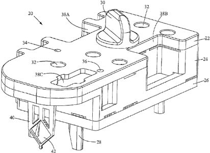
Fig. l~shows an isometric view of a cartridge 20 according~to
the preferred embodiment. The cartridge 20 is designed to
separate nucleic acid from a fluid sample and to hold the
nucleic acid for amplification and detection. The cartridge 20
has a body.comprising a top piece 22, a middle piece 24, and a.
bottom piece 26. An inlet port for introducing a fluid sample
into the cartridge is formed in the top piece 22 and sealed by a
cap 30.- Six pressure ports 32 are also formed in the top piece
22. The pressure ports 32 are for receiving nozzles from
pressure sources, e.g., pumps or vacuums. The cartridge also
includes alignment legs 28 extending from the bottom piece 26 .
for positioning the cartridge 20 in an instrument (described .
below.with reference to Fig. 10). Indentations or depressions
38A, 38B, and 38C are formed in the~top and middle pieces 22,
24. The indentations~are for receiving optical sensors that
detect fluid flow in the cartridge 20. The cartridge 20 further
includes vents 34, 3.6. Each pressure. port and vent preferably
includes a hydrophobic membrane that allows the passage of gas _ .
2o but not liquid intovor out of the vents and pressure ports.
Modified acrylic copolymer membranes are commercially available
from,-e. g., Gelman Sciences (Ann Arbor, MI) and particle-track
etched polycarbonate membranes are available from Poretics, Inc.
(Livermore, CA).
Fig. 2 is an isometric view showing the underside of the
cartridge 20. Nine holes 60 are formed in the bottom piece 26
for~receiving valve actuators that open and close valves in the .
cartridge 20. A hole 62 is also foimed in the bottom piece 26
for receiving a transducer (described in detail below with
.reference to Fig. 5). The cartridge 20 also includes a reaction
vessel 40 extending outwardly from the body of the cartridge.
The vessel 40 has a reaction chamber 42 for holding a reaction .
mixture~(e.g., nucleic acid mixed with amplification reagents
Air no~ket# aasso-ooa~pc~r is
AMENDED SHEET
CA 02373249 2001-11-05
12-04-2001 ~ US 000014740
CA 02373249 2001-11-05
and fluorescent probes) for chemical reaction and optical
detection.. One of the flow paths in the cartridge carries the
reaction mixture to the chamber 42 for chemical reaction and
optical detection. The vessel 40 extends outwardly from the
body of the cartridge 20 so. that the vessel 40 may be inserted
between a pair of opposing thermal plates~(for heating and
cooling the chamber 42) without the need for decoupling the
vessel 40 from the rest of the cartridge 20. This greatly
reduces. the risk of contamination and/or spilling. The vessel
40 may be integrally formed with the body of the cartridge
(e. g., integrally molded with middle piece 24). It is presently
preferred, however; to produce the vessel 40 as.a separate
element that is coupled to the body during manufacture.of~the
cartridge.
i5
Figs. 3-4 show exploded views of the cartridge. As shown in Fig.
3, the middle piece 24 has multiple chambers formed therein. In
particular, the middle piece 24 includes a sample chamber 65 for
holding a fluid sample introduced through the inlet port 64, a
wash chamber 66 for holding a wash solution, a reagent chamber
67 for holding a lysing reagent, a waste chamber 68 for
receiving used sample and wash solution, a neutralizer chamber
70 for holding a neutralizer, and a master mix chamber 71 for
holding a master mix (e.g.. amplification~reagents and
fluorescent probes) and for mixing the reagents and probes~with
analyte separated from the fluid sample. The sample chamber 65
optionally includes: a side compartment 155 having slightly lower
walls than the sample chamber 65. The side compartment 155 is'
for visually indicating to a user when sufficient sample has
been added to the sample chamber 65, i.e., when the liquid level
in the chamber 65 is high enough to spill over into the
compartment 155.
ATZ'Y DoCknt~ aasso-ooa~pc-r Za
AMENDED SHEET
12-04-2001 ' US 000014740
CA 02373249 2001-11-05
The, top .piece 22 includes the vents 34, 36 and the six pressure
'ports 32, as previously described: An elastomeric membrane or
gasket 61-is positioned and squeezed between the pieces 22, 24
.to seal the various channels and chambers formed in the pieces.
The middle piece 24 preferably includes multiple sealing lips to.
ensure that the gasket 61 forms an adequate seal. In
particular, the middle piece 24 preferably includes sealing. lips
- 73 surrounding each of the chambers 65, 66, 67, 68. 70, and 71.
The middle piece 24 also includes support walls 75 around the
perimeter, and intermediate sealing lips 76.. The sealing lips.
73, 76- and support walls 75 locally compress the gasket 61 and
achieve a seal. .
- As shown in Fig. 4, the middle piece 24 has formed in its
underside various channels, one of which leads to- a lysing
chamber 86. The chamber 86 is aligned with the hole 62 in the
bottom piece 26 so that a transducer (e. g., an ultrasonic horn)
may be inserted through the hole 62 to generate dynamic pressure
- pulses or pressure waves in the lysing chamber 86. The middle
piece 24 also has nine valve. seats 84 formed in its bottom
surface. The valve seats 84 are aligned with the nine holes 60
in the bottom piece 26 so that valve actuators maybe inserted
through the holes 60 into the valve seats'84.
An elastomeric membrane or gasket 61 is positioned and squeezed
between the pieces 24, 26 to seal the various channels, valve
seats, and chamber formed in the middle piece 24. The middle -
piece 24 preferably includes multiple sealing lips to ensure
- that the gasket 63 forms an adequate seal.. In particular, the
middle piece 24 preferably includes sealing lips 73 surrounding
the lysing chamber 86, valve seats 84, and various channels. The
- middle piece 24 also includes support walls 75 around its
perimeter, and intermediate sealing lips 76. The sealing lips
73-, 76 and support walls 75 locally.compress the gasket 63 and
Arc nockee# aasso-ooa~pcr i4
AMENDED SHEET
12-04-2001 ~ US 000014740
achieve a seal. In addition to sealing various channels and
chambers, the gasket 63 also functions as a valve stem by
compressing, when.actuated through one of .the holes 60, into a
.~correspondingwalve seat 84, thus shutting one of the flow
channels in the middle piece 24. This valve action is discussed
in greater detail below with reference to Figs. 15-16.
The gasket 63 also forms the bottom wall of the lysing chamber
86 against which a transducer is placed to effect disruption of
cells or viruses in the chamber 86. Each of the gaskets 61, 63
is preferably composed of an elastomer: Suitable gasket .
materials are silicone rubber, neoprene, EPDM, or any other
compliant material. Each of the gaskets 61, 63 preferably has a
thickness in the range of 0.005 to 0.125 inches (0.125 to 3.175
mm), and more preferably in the range ~of 0.01 to 0.06 inches .,
(0.25 to 1~.5 mm), with a presently preferred_thickness of .031
,inches (0.79 mm). The thickness is selected to ensure that the
gasket is sufficiently compliant to seal the channels and
chambers, to compress into the valve seats 84 when forced, and
to expand under pressure to contact the transducer.
As shown in Fig. 3, the middle piece 24 includes a slot 79
through which the reaction vessel 40 is.inserted during assembly
of the cartridge. The vessel 40 has two fluid ports 4I, 43 for
adding and.removing fluid from the vessel. when the top piece 22
is sealed to the middle piece 24 via the gasket 61, the ports
41, 43 are placed into fluidic communication with channels 80,
81, respectively, that are formed in the top piece 22 (see Fig.
4). The gasket 61 seals the respective fluidic interfaces
between the ports 41, 43 and the channels 80, 81. The top,
middle, and bottom pieces 22, 24; 26 are preferably injection
molded parts made of a polymeric material such as~polypropylene,
polycarbonate, or acrylic. Although molding is preferred for
mass production, it also possible to machine the top, middle,
Air nooxet~ aasso-ooa~prr is.
AMENDED SHEET
CA 02373249 2001-11-05
12-04-2001 ~ US 000014740
CA 02373249 2001-11-05
and bottom pieces 22, 24, 26. The pieces 22, 24, 26 may be held
together by screws or~fastenere. Alternatively, ultrasonic
bonding, solvent bonding, or snap fit designs could be used to
assemble the cartridge.
Fig. 4 also shows a filter ring 88. The filter ring 88
compresses and holds a stack of filters in the lysing chamber
86. Fig. 6 shows an exploded view of a filter stack 87. The .
purpose of the filter stack 87 is to capture cells or viruses
t0 from a fluid sample as the sample flows through the lysing
chamber 86. The captured cells or viruses are then disrupted
(lysed) in the chamber 86. The cells may be animal or plant
cells, spores, bacteria, or microorganisms. The viruses may be,
any type of infective agents having a protein coat surrounding
an RNA or DNA core. -
The filter stack_87 comprises a gasket 93, a fir.at filter 94, a
gasket 95, a second filter 97 having a smaller pore size than
the first filter 94, a gasket 98, a third filter 100 having a
2o smaller pore size than the second filter 97, a gasket 101, a
woven mesh 102, and a gasket 103. The filter stack also
preferably includes a first set of beads 96 disposed between the
first and second filters 94 and 97 and a second set of beads 99
disposed between the second and third filters 97 and 100. The
filter ring 88 compresses-the filter stack 87 into the.lysing
chamber 86 so that the gasket.93 is pressed against the-filter
94, the filter 94 is pressed against the gasket 95, the gasket
95 is pressed against the-filter 97, the filter 97 is pressed
against the gasket 98, the gasket 98 is pressed against the
filter 100, the filter 100 is pressed against the gasket 101,
the gasket 101 is.pressed against the mesh 102, the mesh 102 is
pressed against the~gasket 103, and the gasket 103 is pressed
against the outer perimeter of the bottom wall of, the lysing
chamber 86. The gasket 95 is thicker than the average diameter
ATTY DoCket~ 22660-OOa7PCT 16
AMENDED SHEET
12-04-2001 ~ . US 000014740
CA 02373249 2001-11-05
' of the~beads 96 so that the beads are free to move in the space
between the filters 94 and 97. Similarly, the gasket 98 is
thicker than the average diameter of the beads 99 so that the
beads 99 are free to move in the~space between the filters 97 '
and 100. A fluid sample flowing through the channel 106 into the
lysing chamber 86~first flows through filter 94, then through
filter 97, next through filter 100, and lastly through the mesh
102. After flowing through the filter stack 87,~ the sample
flows along flow ribs 91 formed in the top of the lysing chamber
86 and through'an outlet channel (not shown in Fig. 6?. '
Referring to Fig. 5, the cells or viruses captured in the filter
stack (not shown in Fig. 5 for illustrative clarity) are lysed
by coupling a transducer 92 (e. g., an ultrasonic horn) directly
to the wall of the lysing chamber 86. In this embodiment, the
wall of the lysing chamber 86 is~formed by the flexible gasket
.63. The transducer 92 should directly contact an external
surface of the wall. The term "external surface" is intended to
mean a surface of the wall that is external to the lysing
chamber 86. The transducer 92' is a vibrating or oscillating
device that is activated to generate dynamic pressure pulses or
pressure waves in the chamber 86. The pressure waves agitate the
beads .96, 99 (Fig. 6), and the movement of the beads ruptures
the captured cells or viruses. In general, the transducer for
contacting the wall of the lysing chamber 86 may be an .
ultrasonic, piezoelectric, magnetostrictive, or electrostatic
transducer. The transducer may also be an electromagnetic device
having a wound coil, such as a voice coil. motor or a solenoid.
device. It is presently preferred that the actuator be an
ultrasonic transducer, such Asian ultrasonic horn. Suitable horns
are commercially available from Sonics & Materials, Inc. having
an office at 53 Church Hill, Newton, Connecticut 06470-1614 USA.
Alternatively, the ultrasonic transducer may comprise a
piezoelectric disk or any other type of~ultrasonic transducer
ATTY Dockat$ 2x660-0027pCT 17
AMENDED SHEET
12-04-2001 , ~ US 000014740
CA 02373249 2001-11-05
that may be coupled to the container. It is presently preferred
to use an ultrasonic horn because the horn structure is highly
resonant and provides for repeatable and sharp frequency of
excitation and large motion of the horn tip.
As previously described in Fig. 6, the filter stack includes a
gasket,at both of its ends. As shown in.Fig. 5, the middle
cartridge piece 24 has a sealing lip 90 against which the gasket
at one end of the filter stack is compressed. The gasket at the
l0 other end of the filter stack is compressed by the filter ring
88 to form a seal.. The gasket material may expand into the
relief area outside of the sealing lip 90. The width of the
sealing lip.90 is small (typically 0.5~mm) so that an excessive
amount of force is not required to achieve a sufficient seal.
The filter ring 88 is held between the filter stack and.the
cartridge gasket 63. The cartridge gasket 63 is held between the
middle piece 24 and the bottom piece 26 by,a sealing lip 406.
Force is therefore transferred from the bottom piece 26 through
the gasket 63 to the filter ring 88 and finally to the filter
stack. The filter ring 88 contains a contact~lip 404 that ,
contacts the gasket 63. The contact. lip 404 is not a primary
sealing lip (though it will seal) but a force transfer
mechanism. The width of the contact lip 404 is larger than the
width of the sealing lip 90 to ensure that'deformation and
sealing action occurs in the filter stack and not taken up in
squeezing the cartridge gasket 63. The cartridge middle piece 24
also has a sealing lip 406 that surrounds the~.filter ring 88.
. This is an active sealing area that should not be compromised by
the~presence of the filter ring 88. For this reason, there is a
gap 407~between the sealing lip 406 and the contact lip 404 on
the .filter ring 88. The gap 407 is provided to allow the gasket
63 to extrude into the gap 407 as it is compressed~by the
sealing lip 406 and the contact lip 404. If the contact lip 404
ATTY Dockot~ 22660-0027PGZ ~ 18
AMENDED SHEET
12-04-2001 US 000014740
comes to a different elevation than the sealing lip 406, the
seal will not be compromised because of the gap 407 and the
distance between the lips 404 and 406.
Referring again to Fig. 6, the filter stack 87 is effective for
capturing cells or viruses as a fluid sample flows through the
stack 87 without_clogging of any of the filters 94, 97, 100 in
the stack. The first filter~94 (having the largest pore size)
filters out coarse material such as salt crystals, cellular
l0 debris, hair, tissue, etc. The second filter 97 (having the
medium pore size) captures cells or viruses in the fluid sample.
The third filter 100 (having the smallest pore size) captures
smaller cells or viruses.in the sample. The filter stack 87
thus enables the simultaneous capture of differently sized
t5 sample components without clogging of the filters. The average
pore size of the first filter 94 is selected to be small enough
to filter coarse material from the fluid sample (e. g., salt
crystals, cellular debris, hair, tissue) yet large enough to
allow the passage of the target cells or.viruses containing the
20 desired analyte (e.g:, nucleic acid or proteins). In general,
the pore size of the first filter 94 should~be in the range of
about 2.to 25 ~tm, with a presently preferred pore size of about
5 ~tm.
25 The average pore sizes of the second and third filters are
selected in dependence upon the average size of the target cells
or viruses that contain the desired analyte(s). For~example, in
one embodiment, the filter stack 87 is used to capture gonorrhea
(GC) and. chlamydia (Ct) organisms to determine the presence of
30 the diseases in the fluid sample. The~GC and Ct organisms have
different average diameters, about 1 to 2 ~,m for GC organisms
and about 0.3-~tm for Ct organisms. In this embodiment, the
second filter 97 has an average pore size of about 1.2 um while
AT1'7C Dockat~l 22660-0027PCT 19
AMENDED SHEET
CA 02373249 2001-11-05
12-04-2001 ' US 000014740
CA 02373249 2001-11-05
the third filter 100 has an average pore size of about 0.22 dim
so that most of the GC organisms are captured by the second.
filter 97 while most of the Ct organisms are captured by the
third filter 100. The filter stack thus enables the
'simultaneous capture of differently sized target organisms and
does so without clogging of the filters. The pore sizes of the
filters 97, 100 may be selected to~capture desired cells or
viruses of any size, and the scope of the invention is not
limited~to the specific example given.
The filter stack 87 is also useful for disrupting the captured
cells or viruses to release the intracellular material (e. g.,
nucleic acid) therefrom. The first and second sets of beads 96,
99 serve two useful purposes in this regard. First, the beads
t5 are agitated by dynamic pressure pulses or pressure waves
generated-by the transducer. The movement of the beads ruptures
the captured cells or viruses. Second, the beads may shear the
nucleic acid released from the lysed cells or viruses so that
the strands of nucleic acid are sufficiently short to flow
through the filters and out of the lysing chamber 86. Suitable -
beads for rupturing cells or viruses include borosilicate glass,
lime glass, silica, and .polystyrene beads.
The beads may be porous or non-porous and preferably have an
average diameter in the range of 1 to 200 ~,m. The average
diameter of the beads 96, 99 is selected in dependence upon. the
intended target cells or viruses to be ruptured by the beads.
The average diameter of the beads 96 in the first set may be
equal to the average diameter of the beads 99 in the second set.
Alternatively, when the first set of beads 96 is used to rupture
a type of target cell or virus that differs from the type of
cell or virus to be ruptured by the second set of beads 99, it
is advantageous to select the average diameter of the beads such
that the average diameter of the beads 96 in the first set
ATTY Dockets 22660-0027PCT 20
AMENDED SHEET
12-04-2001 ~ U S 000014740
differs from the average diameter of the beads 99 in the second
set. For example, when the filter stack is used to capture GC
and Ct cells as described above,.the beads 96 are 20 ~m diameter
boro'silicate glass beads for rupturing the GC organisms and the
beads 99 are 106 ~m diameter soda lime glass beads for rupturing
the Ct organisms.'Each of the silicone gaskets 95, 98 should be
sufficiently thick to allow room for the beads 96,' 99 to move
and rupture the cells or viruses.
The mesh 102 also serves two useful purposes. First the mesh
provides support to the filter stack 87. Second, the. mesh
breaks up air bubbles so that the bubbles can be channeled
through the flow ribs 91 and out of the lysing chamber 86.~To
effectively break up or reduce the size of the air bubbles, the
mesh 102 preferably has a small pore size. Preferably, it is a
woven polypropylene mesh having an average pore size of about 25
Vim. To ensure that the air bubbles can escape from the lysing
chamber 86, it is~desirable to use the cartridge in an
orientation in which liquid flows up (relative to gravity)
through the filter stack 87 and the lysing chamber 86. The
upward flow through the~chamber 86 aids the flow of air bubbles
out of the chamber 86.-Thus, the inlet port for entry of fluids
into the chamber 86 should~generally be at the lowest point in
the chamber, while the exit port should be at the.highest.~
Many different embodiments of the filter stack are possible. For
example, in one alternative embodiment, the filter stack has
only two filters and one set of beads disposed between the
filters. The first filter has the largest'pore size (e.g., 5 Vim)
and filters out coarse material such as salt crystals, cellular
debris, hair, tissue, etc. The second filter has a pore size
smaller than the first filter and slightly smaller than the
target cells or viruses to be captured. -Such a filter stack is
described below with reference to Fig. 38. In another embodiment
ATTY Dockot# SZ660-0027PCT 21
AMENDED SHEET
CA 02373249 2001-11-05
12-04-2001 ' US 000014740
of the cartridge, the filter. having the largest pore size ('for
filtering the coarse material) is positioned in~a filter chamber
(not shown) that is, positioned upstream of the lysing chamber
86. A channel connects to the filter chamber to the lysing
chamber 86. In this embodiment, a fluid sample flows first
through the coarse filter in the filter chamber and then through
a second filter in the lysing chamber to trap the target cells
or viruses in the lysing chamber.
l0 Further, the beads in the filter stack may have a binding,
affinity for target cells or viruses in the fluid sample to
facilitate capture of the target cells or viruses. For example,
antibodies or certain receptors may be coated onto the surface
of the beads to bind target cells in the sample. Moreover, the
lysing chamber 86 may contain two different types of beads for
interacting with target cells or viruses. For example, the
lysing chamber may contain a first set of beads coated with
antibodies or receptors for binding target cells or viruses and
a second set of beads (intermixed with the first set) for
rupturing the captured cells or viruses. The beads' in the lysing
chamber 86 may also have a binding affinity for the.
intracellular material.(e.g., nucleic acid) released from the
ruptured cells or viruses. Such beads are useful for isolating
target nucleic acid for subsequent elution and analysis. For .
25_ example, the lysing chamber may contain silica beads to isolate
DNA or cellulose beads with oligo dT to isolate messenger RNA
for RT-PCR. The lysing chamber 86 may. also contain beads for
removing unwanted material (e.g., proteins, peptides) or
chemicals (e.g.. salts, metal ions, or detergents) from the
3o sample that might inhibit PCR. For example,.the chamber 86 may
contain ion exchange beads for removing proteins. Alternatively
beads having metal ion chelators such as iminodiacetic acid will
remove metal ions from biological samples.
ATTY Docket# ZZ660-0027PCT 22
AMENDED SHEET
CA 02373249 2001-11-05
12-04-2001 US 000014740
Figs. 21-22 illustrate the reaction vessel 40 in greater detail.
Fig. 21 shows a partially exploded view of the vessel 40, and
Fig. 22 shows a front view of'the vessel 40. The vessel 40
includes the reaction chamber 42 (diamond-shaped in this
embodiment) for holding a reaction mixture. The vessel 40 is
designed for optimal heat transfer to and from the reaction
mixture and for efficient optical viewing of the mixture. The
thin shape of the vessel contributes to optimal thermal kinetics
by providing large surfaces for thermal conduction and for
.contacting thermal plates. In addition, the walls of the vessel
provide optical windows into the chamber 4.2 so that the entire
reaction mixture can be optically interrogated. In more detail
to Figs. 21-22, the reaction vessel 40 includes a rigid frame 46
that defines the side walls 57A, 57B, 59A, 59B of the reaction
t5 chamber 42. The frame 46 also defines an inlet'port 41 and a
channel 50. connecting the port 41 to the chamber 42. The~frame
46 also defines an outlet~.port 43 and a channel 52 connecting
the port 43 to the chamber 42. The inlet port~41 and channel 50
.are used to add fluid to the chamber 42, and the channel 52 and
outlet port 43 are used for exit of fluid from the chamber 42.
Alignment prongs 44A, 44B are used to position the vessel 40
correctly during assembly of the cartridge.
As shown in Fig. 21, the vessel 40.also includes thin,,flexible
sheets attached to opposite sides of the rigid frame 46 to form
opposing major walls 48 of the chamber. (The major walls 48 are
. shown in Fig. 1 exploded from the rigid frame 46 for'
illustrative clarity). The reaction chamber 42 is thus defined
by the rigid aide walls 57A, 57B, 59A, 59B of the frame 46 and
by the opposing major walls 48. The opposing.major walls 48 are
sealed 'to opposite sides of the frame 46 such that the side
wa11s~57A, 578, 59A, 59B connect the major walls 48 to each
other. The walls 48 facilitate optimal thermal conductance to
the reaction mixture contained in the chamber 42. Each of the
ATTY Dockat~ 22660-OOZ7PCT 23
AMENDED SHEET
CA 02373249 2001-11-05
12-04-2001 ~ US 000014740
walls 48 is sufficiently flexible to contact and conform to a
respective thermal surface, thus providing~for optimal thermal
contact and heat transfer between the thermal surface and the
reaction mixture contained in the chamber 42. Furthermore, the
flexible walls 48 continue to conform~to the thermal surfaces if
. the shape of the surfaces changes due to thermal expansion or
contraction during the course of the heat-exchanging operation.
As shown in Fig. 23, the thermal surfaces for contacting~the
flexible walls 48 are preferably formed by a pair of opposing
plates 190A, 190B positioned~to receive the chamber 42 between
them. When the chamber 42 of the vessel 40 is inserted between
the plates 190A, 1908, the inner.surfaces of the plates~contact
the walls 48 and the flexible walls conform to the surfaces of
the plates. The plates are preferably spaced a distance from
each other equal to the thickness T of the chamber 42 as defined
by.the thickness of the frame 46. In this position, minimal or
no gaps are found between the plate surfaces and the walls 48. .
The plates may be heated and cooled by various thermal elements
to induce temperature changes within the chamber.42, as is
described in greater detail below.
The walls 48 are preferably flexible films of polymeric material
such as.polypropylene, polyethylene, polyester, or other ..
polymers. The films may either be layered, e.g., laminates, or
the films may be homogeneous. Layered films are preferred
because they generally have better strength and structural
integrity than homogeneous films. In particular, layered
polypropylene films are presently preferred because
polypropylene is not inhibitory to PCR. Alternatively, the walls
48 may comprise any other material.that may be formed into a
thin, flexible sheet and that permits rapid heat transfer. For
good thermal conductance, the thickness.of each wall 48 is
preferably between about 0.003 to 0.5 mm, more preferably
a~r~r no~xet# aasso-ooa~pc~r a4
AMENDED SHEET
CA 02373249 2001-11-05
12-04-2001 US 000014740
CA 02373249 2001-11-05
between 0.01 to 0.15 mm, and most preferably between 0.025 to
0.08 mm.
Referring again to Fig. 22, the vessel 40 also preferably
includes optical windows for in situ optical interrogation of
the reaction mixture in the chamber 42. In the preferred
embodiment, the optical windows are the side walls 57A, 57B of
the, rigid frame 46. The side walls 57A, 57B are optically
transmissive to permit excitation of the reaction mixture in the
chamber.42 through the side wall 57A and detection of light
emitted from the chamber 42 through the side wall 57B. Arrows A
represent illumination beams entering the chamber 42 through the
side wall 57A and arrows B represent emitted light (e. g.,
fluorescent emission from labeled analytes in the reaction
mixture) exiting the chamber 42 through the. side wall 57B.
The side walls 57A, 57B are preferably angularly offset from
each other. It is usually preferred that the walls 57A, 57B are
offset from each other by an angle~of about 90°. A 90° angle
between excitation and detection paths assures that a minimum
amount of excitation radiation entering through the wa11.57A
will exit through'wall 57B..~In addition, the 90° angle permits a
maximum amount of emitted light (e.g. fluorescence) to be
collected through wall 57B. The walls 57A,.578 are preferably
joined to each other to form a "V" shaped intersection at the
bottom of the chamber 42. Alternatively, the angled walls 57A,
57B need not be directly joined to each other, but may be
separated by an intermediary portion, such as another wall or
various mechanical or fluidic features which do not interfere
with the thermal and optical performance of the vessel. For
example, the walls 57A, 57B may meet at a port which leads to
another processing area in communication with the chamber 42,
such as an integrated capillary electrophoresis area. Iri the
presently preferred embodiment, a locating tab 58 extends from
ATTY Dock~t# 22660-OOa7PCT 25
AMENDED SHEET
12-04-2001 US 000014740
the frame 46 below the intersection of walls 57A, 57B. The tab
58 is used to properly position the vessel 40 in a heat-
exchanging module described below with reference to Fig.. 28.
Optimum optical sensitivity may be attained by maximizing the
optical path length of the light beams exciting the labeled
analyte in the reaction mixture and the emitted light that is
detected, as represented-by the equation:
C * L * A,
1U where Io is the illumination output. of the emitted light in
volts,'photons or the like, C is the concentration of analyte to
be detected, Ii is the input illumination, L is the path length,
and A is the intrinsic absorptivity of the dye used to label the
analyte.
The thin, flat reaction vessel 40 of the present invention
optimizes detection sensitivity by providing maximum optical
path length per unit analyte volume. Referring to Figa. 23 and
27, the vessel 40 is preferably constructed such that each of
the sides walls 57A, 57B, 59A, 59B of the chamber 42 has a
length L in the range of 1 to 15 mm, the chamber has a width W
in the range of 1.4 to 20 mm, .the chamber has a thickness T in
the range of 0.5 to 5mm, and the ratio of the width W of the
chamber to the thickness T of the chamber is at least 2:1. These
parameters are presently preferred to provide a~vessel having a
'relatively large average optical path length through the .
chamber, i.e. 1 to 15 mm on average, while still keeping the
chamber sufficiently thin to allow for extremely rapid heating
and cooling of the reaction mixture contained therein. The
average optical path length of the chamber 42 i's the distance
3o from the center of .the side wall 57A to the center of the
chamber 42 plus the distance from.the center of the chamber 42
~to the center of the side wall 57B.
ATx3r nocxet# aasso-ooa~pcr as
- AMENDED SHEET '
CA 02373249 2001-11-05
12-04-2001 ~ ~ US 000014740
CA 02373249 2001-11-05
More preferably, the vessel 40 is constructed such that each of
the sides walls 57A, 57B, 59A, 59B of the chamber 42 has a
length L in the range of 5 to.l2 mm, the chamber has a width W
in the range of 7 to 17 mm, the chamber has a thickness T in the
range of 0.5 to 2 mm, and the ratio of the width W of the
chamber to the thickness T of the chamber is at least~4:l.
These ranges are more preferable because they provide a vessel
having both a larger average optical path length (i.e., 5 to 12
mm) and a volume capacity in the range of 12 to 100 ~1 while
1o still maintaining a chamber sufficiently thin to permit'
extremely rapid heating and cooling of a reaction mixture. The
relatively large volume capacity provides for increased
sensitivity in the detection of low concentration analytes, such
as nucleic acids.
In the preferred embodiment, the reaction vessel 40 has a
diamond-shaped chamber 42 defined by the side walls 57A, 578,
59A, 59B, each of the side walls has a length of about 10~mm,
the chamber has a width of about 14 mm, the chamber has a
2o thickness T of .1 mcri as defined by the. thickness of the frame 46,
and the chamber has a volume capacity of about 100 ~1. This
reaction vessel provides a relatively large average optical'path
length of 10 mm through the chamber 42. Additionally, the thin
chamber allows for extremely rapid heating and/or cooling of the
reaction mixture~contained therein. The diamond-shape of the
chamber 42 helps prevent air bubbles from forming in the chamber
as~it is filled with the reaction,mixture and also aids in
optical interrogation of the mixture.
3o Referring again to Fig. 22, the frame 46 is preferably made of
an optically transmissive material, e.g., a polycarbonate or
clarified polypropylene, so~that the side walls 57A, 57B are
" optically transmissive. As used herein, the term optically
transmissive means that one or more wavelengths of light may be
ATTY DOCkst~ aasso-ooa~ac~ a~
AMENDED SHEET
12-04-2001 US 000014740
CA 02373249 2001-11-05
transmitted through the walls. In the preferred embodiment, the
optically transmissive walls 57A, 57H are substantially .
transparent. In addition, one or more opCical elements may be
present on the optically transmissive aide walls 57A,. 57B. The
optical elements may be designed, for example, to maximize the
total volume~of solution which is illuminated by a light source,
to focus excitation light on a specific region of the chamber
42, or'to collect as much fluorescence signal from as large a
fraction of the chamber volume as possible. In alternative
embodiments, the optical elements may comprise gratings for
selecting specific wavelengths, filters for allowing only
certain wavelengths to pass, or colored lenses.~to~provide
filtering functions.. The wall surfaces may be coated~or comprise
materials such as liquid crystal.~for augmenting the absorption
of certain wavelengths. In~the presently preferred embodiment,
the optically transmissive walls 57A, 57B are substantially
clear, flat windows having a thickness of about 1 mm.
The side walls 59A, 59B preferably includes reflective faces 56
which internally reflect light trying to exit the chamber 42
through the side walls 59A, 59B. The reflective faces 56 are
arranged such that adjacent faces are angularly offset from each
other by about 90°. In addition, the frame.46 defines open spaces
between the side walls 59A, 59B and the support ribs 53. The .
open spaces are occupied by ambient air that has a different
refractive index than the material composing the frame (e. g.,
plastic?. Due to the difference in the refractive indexes,~the
reflective faces 56 are effective for internally reflecting
light trying to exit the chamber through the walls 59A, 59H and
provide for increased detection of optical signal through the
walls 57A, 57B. Preferably, the optically transmissive side
walls 57A, 57B define the bottom portion of the diamond-shaped
chamber 42, and the retro-reflective side walls 59A, 598 define
the top portion of the chamber.
aTrsr aocxet# 22sso-ooa~pcr as
AMENDED SHEET
12-04-2001 ' ~ ' US 000014740
CA 02373249 2001-11-05
A preferred~method for fabricating the reaction vessel 40 will
now be described with reference to Figs. 21-22. The reaction
vessel 40 may be fabricated by first molding the rigid frame. 46
using known injection molding techniques. The frame 46.is
preferably molded as a single piece of polymeric material, e.g.,
clarified polypropylene. After the frame 46 is produced, thin,
flexible sheets are cut to size and sealed to opposite sides~of
the frame 46 to form the major walls 4.8 of the chamber 42. The
major walls 48 are preferably cast or extruded films of
polymeric material, e.g., polypropylene films, that are cut to
size and attached to the frame 46 using the following procedure.
A first piece of film is placed over one side of the frame 46.
The frame 46 preferably includes a tack bar 47 for aligning the
top edge of the film. The film is. placed over the bottom
portion~of the frame 46 such that the top edge of the film is
aligned with the tack bar 47 and such that the film completely
covers the bottom portion of the frame 46 below the tack bar 47'.
The film should be larger than the bottom portion of the frame
20. 46 so that it may be easily held and stretched flat across the
frame. The film is then cut to size to match the outline of the
frame by clamping to t'he frame the portion of the film that
covers the frame and cutting away the portions of the film that
extend past the perimeter of the frame using, e.g., a laser or
die. The film is then tack welded to the frame, preferably
using a laser.
The film is then sealed to the frame 46, preferably by heat
sealing. Heat sealing is presently preferred because it produces
a strong seal without introducing potential contaminants to the
vessel as the use of adhesive or solvent'bonding techniques
might do. Heat sealing is also simple and inexpensive. The heat
sealing may be performed using, e.g., a heated platen. An
identical procedure may, be used to cut and seal a second~sheet
ATTY Dockets 22660-0027PCT 29
AMENDED SHEET
12-04-2001 ' ~ US 000014740
CA 02373249 2001-11-05
to the opposite side of the frame 46~ to complete the chamber 42.
Many variations to this fabrication procedure are possible. For
example, in an alternative embodiment, the film is stretched
across the bottom portion of the frame 46 and then sealed to the
frame prior to cutting the film to size. After sealing the film
to the frame, the portions of the film that extend past the
perimeter of the frame are cut away using, e.g., a laser or die.
Although it is presently preferred to mold the frame 46 as a
.single piece, it is also possible to fabricate the frame from
.multiple pieces. For example, the side walls 57A, 57B forming
the angled optical windows may be molded from polycarbonate,
which has good optical transparency, while the rest of the frame
is molded from polypropylene, which is inexpensive and
compatible with PCR. The separate pieces can be attached
together in a secondary step. For example, the side walls 57A,
57B may be press-fitted and/or bonded to the remaining portion
of the frame 46. The flexible walls 48 may then be attached to
opposite sides o~ the frame 46 as previously described.
Referring again to Fig. 3, it is presently preferred to use a
gasket 61 to seal the ports 41, 43 of the vessel 40 to
corresponding channels 80,-81 (Fig. 4) in the cartridge body.
Alternatively, fluidic seals may be established using a luer
fitting, compression fitting, or swaged fitting. In another
embodiment, the cartridge body and frame of the vessel 40 are
molded as a single part,' and the 'flexible major walls of the
vessel are heat-sealed to opposite sides of the frame.
Referring again to Fig. 22, the chamber 42 is filled by forcing
liquid (e.g.,~ a reaction mixture) to flow through the port 41~
and the channel 50 into the chamber 42. The liquid may be forced
to flow into the chamber 42 using differential pressure (i.e.,
either pushing the liquid through the inlet port 41 or
ATTY Dockets aassa-oaa~rcr. as
AMENDED SHEET
12-04-2001 US 000014740
CA 02373249 2001-11-05
aspirating the liquid by applying a vacuum to the outlet port
43). As the liquid fills the chamber 42, it. displaces air in the
chamber. The displaced air exits the chamber 42 through the
channel 52 and the port 43. For~optimal detection of analyte in
the chamber 42, the chamber should not contain air bubbles. To.
help prevent the trapping of air bubbles in the chamber 42, the
connection between the chamber 42 and the outlet channel-52
should be at the highest point (with respect to gravity) in the
chamber 42. This allows air bubbles in the chamber 42 to escape
without being trapped. Thus, the vessel 40 is designed to be
used in the vertical orientation shown in Fig. 22.
Fig. 25 shows another vessel 206 designed to be used~in a
horizontal orientation. The vessel 206 has an inlet port 41 and
an inlet channel 50 connecting the inlet port 41 to the bottom
of the chamber 42. The vessel also has an outlet port 43 and an
outlet channel 50 connecting the outlet port 43 to the top of
the chamber 42. Thus, any air bubbles in the chamber 42 may
escape through the outlet channel 52 without becoming trapped.
Fig. 26 shows another vessel 207 having two inlet ports 41, 45
and one outlet port 43. Inlet channels 50, 54 connect the
respective inlet ports 41, 45 to the chamber 42, and outlet
channel 52 connects the chamber 42 to outlet port 43. Many other
different embodiments of the vessel are also possible. In each -
25. embodiment, it is desirable to evacuate the chamber 42 from the
highest point (with respect to gravity? in the chamber and to
'. introduce liquid into the chamber from a lower point.
Figs. 15A-15H illustrate two types of valves used in the
cartridge. As shown in Fig. 15A, there are two types of
fundamental concepts to the valve action, and hence two types of
valves. The first valve uses a cone-shaped or conical valve seat
160 formed in the middle cartridge piece 24. The valve seat 160
is a depression, recess, or cavity molded or machined in the
ATTY Docket# 22660-0027PCT 31
AMENDED SHEET
12-04-2001 ~ US 000014740
CA 02373249 2001-11-05
middle piece 24. The valve seat 160 is in fluid communication
with a chamber 167 through a port or channel 157 that intersects
the center of the conical valve seat 160. As shown in Fig. 15B,
a valve actuator 164 having a spherical surface is forced
against the elastic membrane 63 and into the valve seat 160,
establishing a~circular ring of contact between the membrane 63
and the valve seat 160. The kinematic principle is that of a
ball seated into a cone. The circular seal formed by the
membrane 63 and valve seat 160 prevents flow between the channel
157 (and hence the chamber 167) and a side channel 158 extending
from a side of the valve seat 160. The side channel 158 is
defined. by the membrane 63 and the middle cartridge piece 24.'
As shown in Fig. 15A, the other type of valve controls the cross
flow between the channel 158 and another side channel 159 formed
between the membrane 63 and the middle cartridge piece 24. In
this case, a circular ring of contact would be ineffective.
Instead, the second valve.comprises a~recess depression or
cavity 161 formed in the middle cartridge piece 24. The cavity
161 separates the channels 158, 159 from each other. An end of
the channel 158 is positioned on one side of the cavity 161, and
an end of the channel 159 is positioned on the opposite side of
the cavity 161. The cavity 161 is defined by a first curved
surface 162A positioned adjacent the end of the channel 158, a
second curved surface 162B positioned adjacent the end of the
channel 159,~and a third surface 163 between the first and
second curved surfaces 162A, 162B.~As shown 'in Fig. 158, the
curved surfaces provide two valve seats that are the primary
contact area for the membrane 63 to seal off the flow between
'the channels 158 and 159. The kinematic principle is that of a
ball (or spherical end on a valve actuator) held by three
contact points, the upward force on the actuator and the two
valve seats 162A, 162B.
ATTY Dockat~ 22660-00278CT~ 32
AMENDED SHEET
12-04-2001 . US 000014740
As shown in Fig. 16A,.the first and second curved surfaces 162A,
1628 are preferably concentric spherical surfaces. The valve
actuator 164~has also has a spherical surface for pressing the .
membrane 63 tightly against the surfaces 162A, 1628. In
addition,~each of the surfaces 162A,-1628 preferably has a
spherical radius of curvature R1 equal to the combined radius of
curvature R2 of the valve actuator 164 plus the thickness T of
the membrane 63. For example, if the radius of curvature R2 of
the surface of the valve actuator~164 is .094 inches and the'
membrane 63 has a thickness T of 0.031 inches, then the radius
of curvature R1 of each of the surfaces 162A, 1628 is 0.125
inches. In general, the~size and~radius of curvature of the
valve seats is dependent upon the size of the channels in the
cartridge.. The valves are preferably made just large enough to
effectively seal the channels but no larger so that dead volume
in the cartridge is minimized.
As shown in Fig. 168, the third surface 163 is recessed from the
first. and second surfaces 162A, 1628 to provide.a gap 166
between the membrane 63 and the third surface 163 when the
membrane 63 is pressed against the first and second surfaces
162A, 1628.. Stated another way, the surfaces 162A, ~162B are
raised-or elevated from the surface 163. The gap 166 ensures
that the membrane 63 contacts primarily the valve seats 162A,
1628 rather than the entire surface of the cavity 161 so that
maximum pressure is applied to the valve seats 162A and 162B by
the membrane 63. This provides a very strong seal with minimal
actuator force required.
Referring again to Fig. 15B, in both types of valves. the
respective kinematic principle defines the location of the
mating parts. In both the ball-in-cone concept and the ball-
against-two-spherical-surfaces concept, the ball or spherical
shaped valve actuator is permitted to seek its own~location as
ATx~r ao~xets lasso-ooa~pcT la
AMENDED SHEET.
CA 02373249 2001-11-05
12-04-2001 US 000014740
CA 02373249 2001-11-05
it is forced against the valve seat(s). There is a deliberate
clearance,(e.g., 0.01 to 0.03 inches) between the valve actuator
and the hole in the bottom cartridge piece 26 in which the
actuator 164 travels so that only the valve seat action defines
the location of the mating pieces.
The valve actuators can be controlled by a variety of
mechanisms. Figs. 17-19 illustrate one such mechanism. As
shown in Fig. 17, a valve actuator 172 has a spherical surface
0 for pressing~the gasket 63 into a valve seat. The actuator 172
also has a flange 177 on its bottom portion. The cartridge
includes an elastic body, such as~a spring 174, that~pushes
,against a ledge in the lower cartridge piece-26 to bias the
valve actuator against the gasket 63. The spring 174 is
sufficiently strong to close the valve unless a deliberate force
is applied to pull down the 'actuator 172. The valves in the
cartridge may be kept closed in this manner for shipping and .
storage before the cartridge~is used. . Thus, the cartridge may
be preloaded during manufacture with the necessary reagents and
wash solutions to analyze a fluid sample without the fluids
leaking out of the cartridge during shipping and storage.
The actuator pull-down mechanism is usually located in an'
instrument into which the cartridge i.s placed for sample
analysis (one such instrument is described in detail below with
reference to Fig. 10).-The mechanism comprises a sliding guide.
175 that rotates a hinged pull-down member 180 having a jaw 181
for receiving the flange 177 of the actuator 172. As shown in
Fig. 18, the sliding guide 175 rotates the hinged pull-down
member 180 until the flange 177 is. positioned within the jaw
181. As shown in Fig. 19, a solenoid 146. pulls down the member
180 and thus the valve actuator 172 so that the gasket 63 is
released from the valve seat, thus opening the valve and
permitting fluid flow between the channels 170 and 171.
ATTY Dockets 22660-0027PC~ 34
AMENDED SHEET
12-04-2001 ~ US 000014740
CA 02373249 2001-11-05
Fig. 20 illustrates the manner in which fluid flow into and out
of the sample chamber, wash chamber, neutralizer chamber, and
reagent chambers is controlled in the cartridge: Each of these
chambers, as illustrated by a chamber 414 in Fig. 20, is covered
by a hydrophobic membrane 410 that allows the passage of gas but
not liquid therethrough. The hydrophobic membrane 410 is.
positioned between the chamber 414 and a pressure port 32. The
pressure port 32 is formed in the upper cartridge piece 22 and
positioned over the chamber 414. The membrane 410 holds liquids
in the chamber 414 during shipping and storage of the cartridge,
even if the cartridge is turned upside down. The pressure port
32 is sized to receive a pressure nozzle 182 that is connected
to a pressure source (e. g., a vacuum or pneumatic pump) usually
t5 located in the external instrument. The nozzle 182 includes an
o-ring 184 and a flange 415. A spring 185 pushes against the
flange 415 to force the nozzle 182 into the pressure port 32 so
that the o-ring 184~establiahes.a seal around the port 32. In
operation, positive air pressure or a vacuum is applied to the
chamber 414 through the pressure port 32 to force liquids out of
or into, respectively; the chamber 414.
A conical valve seat 160 (previously described with reference to
Figs. 15A-15B) is formed in the middle cartridge piece 24 below
the chamber 414 to control the flow of liquid between the
chamber 414 and a connecting channel 411. The valve is opened
and closed by a valve actuator 188 having a flange 187 and a
spring 188 pressing against the flange. to hold the valve closed
until a downward force is applied to the actuator 186. The
downward force. is preferably supplied by a solenoid that pulls
down the actuator 186 to open the valve. The valve actuator 186
and solenoid are preferably located in the instrument.
ATTY Dock~t~t 82660-0027PCT 35
AMENDED SHEET
12-04-2001 ' US 000014740
Figs. 7-8 show top and bottom plan views, respectively, of the
cartridge. Fig. 9 is a schematic block diagram 'of the cartridge.
As shown i.n any of Figs. 7-9, the cartridge includes a sample
chamber 65 having a port for adding a fluid sample to the
cartridge and a sample flow path extending from the sample
chamber 65. The sample flow path extends from the sample chamber
65 through a valve~10~7 and into a channel 106. The channel 106
includes a sensor region 136 in which the channel 106 has a flat
bottom enabling easy optical detection of the presence of liquid
in the channel. The sample flow path continues. from the channel
106 into the lysing chamber 86 and through the filter stack 87.
The sample flow path also includes a channel 109 for exit of
fluid-from the lysing chamber 86, a channel 110 having.a flat-
bottomed detection region 137, a valve 111, and a channel 112
is leading to the vented waste chamber 68 through a valve 114.
The cartridge also includes the wash chamber 66~for holding wash
solution and the reagent chamber 67 for holding lysing reagent.
The wash chamber 66 is connected to the lysing chamber.86 __
through a valve 115, channel 117, and channel 106. The reagent
chamber 67 is connected to the lysing chamber 86. through a valve
119, channel 117, and channel 106. Sample components (e. g.,
cells or viruses in the sample) are captured in the filter stack
87 and lyaed in the chamber 86 to release target analyte (e. g.,
nucleic acid) from the sample components. The cartridge also
includes an analyte flow path extending from the lysing chamber
86 for carrying the analyte separated from the fluid sample to
the reaction vessel 40 for chemical reaction and optical
detection: The analyte flow path extends from the chamber 86
through the channel 109, channel 110, and valve 111. After
passing through the valve 111, the analyte flow path diverges
from the sample flow path. While the sample flow path extends
though channel 112 into the waste chamber 68, the analyte flow
path diverges into the U-shaped channel 122. The analyte flow
ATTY Docketl~ 22660-0027PCT 36
AMENDED SHEET
CA 02373249 2001-11-05
12-04-2001 - US 000014740
path then extends into and out of the neutralizer chamber 70
through a valve 124. The analyte flow path also passes into and
out of the~master mix chamber 71 through a valve 126. From the
master mix chamber 71, the analyte flow path extends along the
channel 122, through a valve 127, through channel 80, and into
the.reaction vessel 40 through the port 41.
The reaction vessel 40 includes the port 41 for adding a
reaction mixture to the vessel, and the port 43 for exit of
fluids (e. g:, air or excess reaction mixture) from the vessel.
The cartridge also includes channel 81 in fluid communication.
with the. port 43. The channel 8l includes a flat-bottomed
detection region~130 for detecting the presence of liquid in the
'channel. The channe1.81 connects to a channel'131 (channel 131
~5 extends straight down perpendicular to the page in the top plan
view of Fig: 7). Channel 131 connects to a channel 132 which in
turn connects to a channel 134 through a valve 133 (channel 134
extends straight up perpendicular to the page in the top plan
view of Fig. 7). The channel 134 leads to the vent 36 which has
a hydrophobic membrane to permit the escape of gas but not
liquid from the cartridge. The channels, vent and valve
positioned downstream from the reaction vessel 40 are used to
pressurize the chamfer 42 of the vessel, as is described in the
operation section below.
The cartridge also includes a first pressure port 105 positioned
above the sample chamber 65, a second pressure port 116
positioned above the wash chamber 66, a third pressure port 118
positioned above the reagent chamber 67, a fourth pressure port
123 positioned above the neutralizer chamber 70, a fifth
pressure port 125 positioned above the master mix chamber 71,
and a sixth pressure port 128 positioned at the end of the U-
shaped channel 122. The cartridge further includes sensor
chambers 120 and 121 in fluid communication with the waste
A~rx Do~ket~ aasso-oos~pc-r
AMENDED SHEET
CA 02373249 2001-11-05
12-04-2001 US 000014740
chamber 68. The sensor chambers 120 and 121 indicate when
predetermined volumes of liquid have. been received in the waste
chamber 68, as is described in detail below.
Referring to Fig. l0, the cartridge is preferably used in
combination with an instrument 140 designed to accept one or
more of the cartridges. For clarity~of illustration, the
instrument 140 shown in Fig. 10 accepts just one cartridge. It
is to be understood, however, that the instrument may be . , .
i0 designed to process multiple cartridges simultaneously. The
instrument 140 includes a cartridge nest 141 into which the
cartridge is placed for processing. The instrument 140 also
includes the transducer 92 (e.g., an ultrasonic horn) for
generating dynamic pressure pulses-or pressure waves in the
lysing chamber of the cartridge, nine valve actuators 142 for
actuating the nine valves in the cartridge, nine corresponding
solenoids 146 for pulling down the valve actuators, and six
pressure nozzles 145 for interfacing with six corresponding
pressure ports formed in the cartridge. In addition, the
instrument includes or is connected to one or more regulated
pressure sources for supplying pressure to the cartridge through
the pressure nozzles 145. Suitable pressure sources include
syringe pumps, compreased.air sources, pneumatic pumps, or
connections to external sources of pressure. The instrument
further includes three slotted optical sensors 143 and three
reflective optical sensors 144.
Fig. 13 illustrates the slotted optical sensors 143 positioned
to detect liquid in the sensor chambers 120, 121 and in the
30, reagent chamber 67. Each sensor 143'includes.a built in~LED and
photodiode positioned on opposite sides of the sensor. The LED
emits a beam that is detected by the photodiode if the beam is
not' substantially~refracted. Such slotted optical sensors are
commercially available from a number of suppliers. The
Asr~r aoaket# aasso-ooa~pcr 3e
AMENDED SHEET
CA 02373249 2001-11-05
12-04-2001 ~ US 000014740
cartridge is shaped so that the slotted optical sensors fit
around the chambers 67, 120; and 121. The operation of each
sensor is as follows. If liquid is not present in the chamber
the sensor surrounds, the beam from the LED is substantially
refracted by air in the chamber and the curved inner walls of
the chamber and only a weak signal, if any, is detected by the
photodiode.since air has an index.of refraction that does not
closely match that of the plastic cartridge. If there is liquid
present in the chamber, however, the beam from the LED does not
to refract or is only slightly refracted and produces a much
stronger signal detected by the photodiode since the liquid has
an index of refraction closely matching that of the plastic
cartridge. The optical sensors 143 are therefore useful for
determining the presence or absence of liquid in the chambers
67, 120, and 121.
Fig. 14 shows a cut-away, schematic side view of the sensor
chamber 120 in fluid communication with the waste chamber 68 and
surrounded by the slotted optical sensor 143. The sensor
chamber 120 and sensor 143 are used to indicate when a
predetermined volume of liquid is present in the waste chamber
68. The sensor chamber 120 is partially separated from the waste
chamber 68 by a wa11~151 having a spillover rim 152.. The height
of the wall is selected so that when the predetermined volume of
liquid is received in the waste chamber 68, the liquid spills
over the~spillover rim 152 and into the sensor chamber 120. The
liquid in the sensor chamber 120 is then detected by the sensor
143. '
3o Referring again to Fig. 13, the cartridge may also include a
second sensor chamber 121 in fluid communicatian.with the waste
chamber 68. The second sensor chamber 121 is also separated
from the waste chamber 68 by a wall 153 having a spillover rim.
The wall 153 is taller than the wall 152 so that liquid does not
n~°rw aocxat~ lasso-ooa~pc~r ss
AMENDED SHEET
CA 02373249 2001-11-05
12-04-2001 ' US 000014740
spill over the wall 153 until a second predetermined volume of
fluid in addition to the first predetermined volume of fluid has
been received in the waste chamber 68. The sensor chambers 120,
121 and the optical sensors 143 are useful for controlling the
operation of the cartridge. The height of the wall 152 is
preferably selected such that when a fixed volume of fluid
sample'from.the sample chamber 65 has flowed through the sample
flow path to the waste chamber 68, the sample liquid spills over
into the sensor chamber 120 and is detected. The detection in
t0 chamber 120 triggers the release of wash solution from the wash
chamber 66 which flows through the sample flow path to the waste
chamber 68. When an incremental volume of the wash solution is
received in the chamber.~68., liquid spills over the wall 153 into
.the sensor chamber 121 and is detected. The detection of liquid
in the chamber 121 then triggers the release of lysing reagent
from the chamber 67. The sensor 143 surrounding the chamber 67
may then be used to indicate when the chamber 67 is empty,
triggering the start of ultrasonic lysis. In an alternative
embodiment, the cartridge may have two waste chambers, one for '
sample and one.for wash, with each waste chamber having a
respective sensor chamber connected thereto.
In-line reflective optical sensors 144 are used to determine the
presence or absence of liquid in the flat-bottomed detection
regions 130, 136, 137, of channels 81, 106, and,110,
respectively (Fig. 7). Each sensor 144 has a built in~,emitter
and detector that is positioned over a flat-bottomed detection
region.' The emitter emits a beam that is reflected from the
cartridge and detected by the detector. The sensor detects a
change in signal when as an air/liquid .interface passes through
the detection region. Optionally, dual emitter reflective
optical sensors~may~be used for a more reliable detection
operation. Both types of reflective optical sensors are well.
known in the art and commercially available.
ATTY Docket# 22660-OOa?PCT ~ 40
AMENDED SHEET
CA 02373249 2001-11-05
12-04-2001 US 000014740
CA 02373249 2001-11-05
Referring again. to Fig. 10, the instrument 140 also includes a.
heat-exchanging module 147 having a slot 148 for receiving the
reaction vessel of the cartridge. The module 147 is described in
detail below with reference to Fig. 28. The instrument 140
further includes a latch mechanism 149 for latching a hid 150
over a cartridge. The cartridge nest 141. includes alignment.
holes 401 for receiving the legs of the cartridge. The
alignment holes 401 ensure proper positioning of the cartridge
in the nest 141 so that the pressure nozzles 145, transducer 92,
. and valve actuators 142 fit into the corresponding ports in .the
cartridge and so that the reaction vessel fits into the slot
'148. The transducer 92 should be positioned in the instrument
140 such that when the cartridge is placed in the nest 141,, the
t5 transducer contacts the bottom wall of the lysing chamber 86, as
shown in the cut-away view of Fig. 5. In addition, the
instrument may include a spring or similar mechanism to bias the
transducer 92 against the wall of the lysing.chamber 86.
The instrument 140 also includes various conventional equipment
not shown in Fig. 10 including a main logic board having a
microcontroller for controlling the operation of the solenoids
146, transducer 92', heat-exchanging module 147, and optical '
sensors 143, 144. The instrument also includes or is connected.
to a power supply for powering the instrument and a pneumatic
pump for.supplying air pressure through the nozzles 145. The
instrument 140 is preferably computer-controlled~using, e.g.,
the microcontroller~which is programmed to perform the functions
described in the operation section below. Alternatively, the
instrument may controlled by a separate computer, or controlled
by a combination of a separate computer and an on-board
microcontroller.
Fig. 11 shows an isometric view of the cartridge 20 placed in
ATTY Dockat~'22660-0027PCT. 41
AMENDED SHEET
12-04-2001 US 000014740
the instrument 140 for processing. Fig. 11 shows a partial ~cut-
away view of the instrument 140 with the lid 150 closed.
Referring again to Fig. 11, a memory or microprocessor chip may
optionally be incorporated as part of the cartridge 20. This
chip preferably contains information such as the type of .
-cartridge, program information such as specific protocols for
the processing of the cartridge, tolerances for accept and
reject, serial numbers and lot codes for quality tracking, ,and
provision for storing the results of the processing. Integrated
electronic memory on the cartridge 20 allows for rapid, easy,
and error-free set-up of the. instrument 140 for different
fluidic processing protocols. When the cartridge 20 is inserted
into~the instrument 140, the instrument may electronically
address the memory. on the. cartridge, and thus automatically
receive the appropriate set of instructions for controlling the , .
time-sequence of fluidic operations to be carried out with the
inserted cartridge. The instrument 140 may simply sequentially
retrieve and execute each step in the cartridge's memory, or
download its contents so that the user may edit the sequence
2o using, a.g.., the controller computer.
If suitable memory is included on the cartridge,, such as
writable memory (e. g., erasable programmable read-only memory
(EPROM), electrically erasable programmable read-only memory
~25 (EEPROM), etc., intermediate and final results, based on the
sample introduced into the cartridge, could be written by the
instrument into the cartridge's memory for co-located storage
with .the physical sample after processing. This is particularly
advantageous in applications where archiving of samples and
3o results is necessary,'such as forensics. In addition,. other
information can be stored in the memory on the cartridge, in
unalterable (or alterable) forms. For example, cartridge serial
number, lot manufacture information, and related information
could be pre-programmed and unalterable. User data, technician
ATTY Dockatl~ ZZ660-0027PCZ ~ 42
AMENDED SHEET
CA 02373249 2001-11-05
12-04-2001 US 000014740
identification number, date of test, location of test and
instrument serial number could be unalterably written into the
cartridge. This allows for easy identification of the "chain of
custody" in the handling of a specimen. Engineers skilled in
the art of data storage will recognize_that other memory means
than electronic can be used, such as optically-addressed printed
regions (e. g., ink-jet or thermal), magnetic strips, etc.
Fig. 28 shows the heat-exchanging module 147 of the instrument
into which the reaction vessel 40 is inserted for thermal
processing and optical detection of target analyte(s) in the
reaction mixture. The module 147 preferably includes a housing
208 for holding the various components of the module. The
module 147 also includes~the thermal platen 190-described above.
t5 The housing 208 includes a slot (not shown in Fig. 28) above the
plates 190 so that the reaction chamber of the vessel 40 may be
inserted through the slot and between the plates. The heat-
exchanging module 147 also preferably~includes a cooling system,
such as a fan 212. The fan 212 is positioned to blow cooling
air past the surfaces of the plates 190 to cool the plates and
hence .cool the reaction mixture in the vessel 40. The housing
.~ 208 preferably defines channels for directing the cooling air
'past the plates 190 .and out of the module 147.
The~heat-exchanging module 147 further includes an optical
excitation assembly 216 and an optical detection assembly 218
for optically interrogating the reaction mixture contained in
the vessel 40. The excitation assembly 216 includes a first
circuit board 220 for holding its electronic components, and the
detection assembly 216 includes a second circuit board 222 for
holding its electronic components.~The excitation assembly 216 '
includes one or more light sources (e.g., an LED. laser, or
light bulb) for exciting fluorescently-labeled analytes in the
vessel 40. The excitation assembly 216 also includes one or more
ATTY Dockets Z~660-0027PCT 43
AMENDED SHEET
CA 02373249 2001-11-05
12-04-2001 US 000014740
CA 02373249 2001-11-05
lenses for collimating the light from the light sources,~as well
as filters for selecting the excitation wavelength ranges of
interest. The detection assembly 218 includes one or more
detectors (e.g., a photodiode, photomultiplier tube, or CCD) for
detecting the light emitted from the vessel 40. The detection
assembly 218 also includes one or more lenses for focusing and
.collimating the emitted light, as well as filters for selecting
the emission wavelength ranges of interest. Suitable optical
excitation and detection. assemblies for use in the heat-
exchanging module 147 are described in International Publication
Number WO 99/60380 (International Application Number
PCT/US99/11182) published November 25, 1999.
The optics assemblies 216, 218 are positioned in the housing 208
such that when the chamber of the vessel 40 is inserted between
the plates 190, the excitation assembly 216 is in optical
communication with the chamber 42 through the optically
transmiasive side wall 57A (see Fig'. 22) and the detection
assembly 218 is in optical communication with the chamber
through the optically transmissive side wall 57B (Fig. 22). In
the preferred embodiment, the optics assemblies 216, 218 are
placed into optical communication with the optically
transmiesive side walls~by simply locating the optics assemblies
216, 218 next to the bottom edges of the plates 190 so that when
.the chamber of the vessel is placed~between the plates, the
optics assemblies 216, 218 directly contact, or are in close
proximity to, the aide walls. .
Fig. 34 shows a partially cut-away, isometric view of the
chamber of the vessel inserted between the plates 190A, 190B
(the top portion of the vessel is cut away). The vessel
preferably has an angled~bottom portion (e. g., triangular)
formed by the optically transmissive,side walls 57A, 57B. Each
of the plates 190A, 190B has a correspondingly shaped bottom
Ax~r aockee# assso-ooa~pc-r
AMENDED SHEET
12-04-2001 US 000014740
CA 02373249 2001-11-05
portion. The bottom portion of the first plate 190A has~a first
bottom edge 250A and a second bottom edge 21908. Similarly, the
bottom portion of the second plate 190B has a first bottom edge
252A and a second bottom edge 2528.. The first and second bottom
edges of. each plate. are preferably angularly offset from each
other by the same angle that the side walls 57A, 57~B 'are offset
from each other (e. g., 90°). Additionally, the plates 190A, 1908
are preferably positioned to receive the chamber of the vessel
between them such that the first side wall 57A is positioned
substantially adjacent and parallel to each of the first bottom
edges 250A, 252A and such that the second-side wall 57B .is
positioned substantially adjacent and parallel to each of the
second bottom edges 21908, 2528. This arrangement provides for
easy optical~access to the optically transmissive side walls
57A, 578 and hence to the chamber of the. vessel. A gel or fluid
may optionally be used to establish or improve optical
communication between each optics assembly and the side walls
57A, 578. The gel or fluid should have a refractive index close
to the refractive indexes of the elements that it is coupling.
Referring again to Fig. 28, the optics assemblies 216, 218 are
preferably arranged to provide a 90° angle between excitation and
detection paths.. The 90° angle between excitation and detection
paths assures that a minimum~amount of excitation radiation
entering through the first side wall of the chamber exits
through the second side wall. Also, the 90° angle permits a
maximum amount of emitted radiation to be collected through the
second side wall. In the preferred embodiment, the vessel 40
includes a locating tab 58 (see Fig. 22) that fits into a slot
3o~.formed between the optics assemblies 216, 218 to ensure proper
positioning of the vessel 40 for optical detection. For improved
detection, the module 147 also preferably includes a light-tight
lid (not shown) that is placed over the top of the vessel 40 and
AT~c aocxat# aasso-ooa~rc~r 4s
AMENDED SHEET
12-04-2001 US 000014740
made light-tight to, the housing 208 after the~vessel is inserted
between the plates 190.
Although it is presently preferred to locate the optics
assemblies 216, 218 next to the bottom edges of the-plates 190,
many other arrangements are possible. For example, optical
communication may be established between the optics assemblies
216, 218 and the walls of the vessel 40 via optical~fibers,
light pipes, wave guides, or similar devices. One advantage of
these devices is that they eliminate the need to locate the
optics assemblies 216, 218 physically adjacent to the plates
190. This leaves more room around the plates in which to
circulate cooling air or refrigerant, so that cooling may be
improved. .
The heat-exchanging module 147 also includes a PC board 226 for
holding 'the electronic components of~the module and an edge
connector 224 for connecting the module 147 to the instrument
140 (Fig. 10). The heating elements and temperature sensors on
the plates 190, as well as the optical boards 220, 222, are
connected to the PC board 226 by flex cables (not shown in Fig.
28 for clarity of illustration).~The module 147 may also include
a grounding trace 228 for shielding the optical detection ..
circuit. The module 147 may optionally include an indicator,
such as an LED 214, for indicating to a user the current status
of the module such as "heating," "cooling," "finished," or
"fault" . .
The housing 208, may be molded from a rigid, high-performance
plastic, or other conventional material. The primary functions
of the housing 208 are to provide a frame for holding the plates
190, optics assemblies 216, 218, fan 212, and PC board 226. The
housing 208 also preferably provides flow channels and ports for
directing cooling air from the fan 212 across the surfaces of
ATTY Dock~t~ Z2660-0027pCT 46
AMENDED SHEET
CA 02373249 2001-11-05
12-04-2001 . . US 000014740
CA 02373249 2001-11-05
the plates 190 and out of the housing. In the preferred
embodiment, the housing 208 comprises complementary pieces (only
one piece shown iri the schematic aide view of Fig. 28) that fit
together to enclose the components of the module 147 between
them.
Referring again to Fig. 23, the plates 190A, 1908 may be made of
various thermally conductive materials including ceramics~or
metals. Suitable ceramic materials include aluminum nitride,
aluminum_oxide, beryllium oxide, and silicon nitride. Other
materials from which the plates may be made include, e.g.,
galliutri arsenide, silicon, silicon nitride, silicon dioxide,
quartz, glass, diamond, polyacrylics, polyamides,
polycarbonates, polyesters, polyimides, vinyl polymers, and
halogenated vinyl polymers, such as polytetrafluoroethylenes.
Other possible. plate materials include chrome/aluminum,
superalloys, zircaloy, aluminum, steel, gold, silver, copper,
tungsten, molybdenum,'tantalum, brass, sapphire, or any of the
other numerous ceramic, metal,. or polymeric materials available
in the art.
Ceramic plates are presently preferred because their inside
surfaces may be conveniently machined to very high smoothness
for high wear resistance, high chemical resistance, and.good
thermal contact to the flexible walls of the reaction vessel.
Ceramic plates can also be made very thin, preferably between
about 0.6 and 1.3 mm, for low thermal mass to provide for
extremely rapid temperature changes: A plate made from ceramic
is also both a good thermal conductor and an electrical
insulator, so that the temperature of the plate may be well .
controlled using a resistive heating element coupled to the
plate.
A~rsr nocket~ aassa-ooa~pcT
AMENDED SHEET
12-04-2001 US 000014740
CA 02373249 2001-11-05
Various thermal elements may be employed to heat and/or cool the
plates 190A, 190B and thus control the temperature of the
reaction mixture in the chamber 42. In general, suitable heating
elements for heating the plate include conductive heaters,
convection heaters, or radiation heaters. Examples of
conductive heaters include resistive or inductive heating
elements coupled to the plates,~e.g., resistors or
thermoelectric devices. Suitable convection heaters include
forced air heaters or fluid heat-exchangers for flowing fluids
~1o past the plates. .Suitable radiation heaters include infrared or .
microwave heaters. Similarly, various cooling elements may be
used to cool the plates. For example, various convection cooling
elements may be employed such as a fan, peltier device,.
refrigeration device, or jet nozzle.for flowing cooling fluids .
past the surfaces of the plates. Alternatively, various
conductive cooling elements may be used, such as a heat sink,
e.g. a cooled metal block', indirect contact with the plates.
Referring to Fig. 24, each plate 190 preferably has a resistive
heating element 206~disposed on its outer surface. The resistive
heating element 206 is preferably a thick or thin film and may
be directly screen printed onto each plate 190, particularly
plates comprising a ceramic material, such as aluminum nitride
or aluminum oxide. Screen-printing provides high reliability and
low cross-section for efficient transfer of heat into the
I
reaction chamber. Thick or thin film resistors of varying
geometric patterns may be deposited.on the 'outer surfaces of the
i
plates to provide~more uniform heating, for example by having
denser resistors at the extremities and.thinner resistors in the
middle. Although it is presently preferred to deposit a heating
element on~the outer surface of each plate, a heating element
may alternatively be baked inside of each plate, particularly if
the plates are ceramic. The heating element 206 may comprise
metals,. tungsten, polysilicon, or other materials that heat when
aT~c aocxat# Zzsso-ooa~ac°r ~e
AMENDED SHEET
~~ 12-04-2001 US 000014740
CA 02373249 2001-11-05
a voltage difference is applied across the material. The heating
element 206 has two ends which are connected to respective
contacts 204 which are in turn connected to a voltage source
(not shown in Fig. 24)~to cause a current to flow through the
heating element. Each plate 190 also preferably includes a
temperature sensor 192, such as a thermocouple, thermistor, or
RTD, which is connected by two traces 202 to respective ones of
the contacts 204. The temperature sensor 192 is be used to
monitor the temperature of the plate 190 in a controlled
feedback loop.
The plates have a low thermal mass to enable rapid heating.and
cooling of the plates. Iri particular, it is presently preferred
that each of the plates has a thermal mass less than about 5
J/°C, more preferably less than 3 J/°C, and most preferably
less
than 1 J/°C. As used herein, the term thermal mass of a plate is
defined as the specific heat of the plate multiplied by the mass .
of the plate. In addition, each plate should be large.enough to
cover a respective major wall of the reaction chamber. In the
2o presently preferred embodiment, for example, each of the plates
has a width X in the range of 2 to 22 mm, a length Y in the
range of 2 to 22 mm, and a thickness in the range of 0.5 to 5
mm. The width X and length Y of each plate is selected to be
slightly larger than the width and length of the reaction
chamber. Moreover, each plate preferably has an angled bottom
. portion matching the geometry of the bottom portion of ~the~
reaction chamber, as previously described with reference to Fig. .
34. Also in the preferred embodiment, each of~the plates is made.
of aluminum nitride having a specific heat of about 0.75 J/g °C.
The mass of each plate is preferably in the range of 0.005 to
5.0 g so that each plate has a thermal mass in the range of
.00375 to 3.75 J/°C.
ATTY.DockeE# 226b0-0027PCT 49
AMENDED SHEET
12-04-2001 ~ US 000014740
CA 02373249 2001-11-05
The opposing plates 190 are positioned to receive,the chamber of
the vessel 40 between them such that~the flexible major walls of
the chamber contact and conform to the inner~surfaces of the
plates. It is presently preferred that the plates 190 be held in
an opposing relationship~to each other using, e.g., brackets,
supports, or retainers. Alternatively, the plates 190 may be
spring-biased towards each other as described in International
Publication Number WO 98/38487. In another embodiment of the
invention, one of the plates is held in a fixed position, and.
l0 the second plate is spring-biased towards the first plate. If
one or more springs are used to bias the plates~towards each
other, the springs .should be sufficiently stiff to ensure. that
the plates are pressed against the flexible walls of the vessel
with sufficient force to cause the walls to conform to the inner
surfaces of the plates.
Figs. 29-30 illustrate a preferred support structure 209 for
holding the plates 190A, 1908 in an opposing relationship to
each other. Fig. 29.shows an exploded view of the structure, and
Fig. 30 shows an assembled view of the structure. For clarity
of. illustration, the support structure 209. and plates 190A, 1908
are shown upside down relative to their normal orientation in
the heat-exchanging module of Fig. 28. Referring to Fig. 29, the
support structure 209 includes a mounting plate 210 having the
slot 148 formed therein. The slot 148 is sufficiently large to
enable the chamber of the vessel to.be inserted through it.
Spacing posts 230A, 2308 extend from the mounting plate 210 on
opposite sides'of the slot 148. Spacing post 230A has
indentations 232 formed on opposite sides thereof (only one side
visible in the isometric view of Fig. 29),' and spacing post 2308
has indentations 234 formed on opposite sides thereof (only one
side visible in the isometric view of Fig. 29). The indentations
232, 234 in the spacing posts are for receiving the edges of the
plates 190A, 190B. To assemble the structure, the plates 190A,
Arr~r nocket~ aasso-ooa~rcr so
AMENDED SHEET
12-04-2001 US 000014740
CA 02373249 2001-11-05
1908 are placed against opposite sides of ~the.spacing posts
230A, 2308 such that the edges of the plates are positioned in
the indentations 232, 234:. The edges of the plates are then
held in~the indentations using a suitable retention means. In
the preferred embodiment, the plates are retained by retention
clips 236A, 2368. Alternatively, the plates 190A, 1908 may be
retained by adhesive bonds, screws, bolts, clamps, or any other
suitable means.
to The mounting plate 210 and spacing posts 230A, 2308 are
preferably integrally formed as a~single molded piece of
plastic. The plastic should be a high temperature plastic, such
as polyetherimide, which will not deform of melt when the plates
190A, 1908 are heated. The retention clips 230A, 2308 are
preferably stainless steel. The mounting plate 210 may '
optionally include indentations 240A, 240B for receiving flex
cables 238A, 2388, respectively, that connect the heating
elements and temperature sensors disposed on the plates 190A,
1908 to the PC board 226 of the heat-exchanging module 147 (Fig.
28). The portion of the flex cables .238A adjacent the plate 190A
is held in the indentation 240A by a piece of tape 242A, and the
portion of the flex.cables 238B adjacent the plate 1908 is held.
in the indentation 240B by a piece of tape 2428.
Fig. 31 is an isometric view of the assembled support structure
209. The mounting plate 210 preferably includes tabs 246
extending from opposite sides thereof for securing the structure.
. 209 to the housing of the heat-exchanging module. Referring
again to Fig. 28, the housing 208 preferably includes-slots for
receiving the tabs to hold the mounting plate 210 securely in
place. Alternatively, the mounting plate 210 may be attached to
the housing 208 using', e.9., adhesive bonding, screws, bolts,
clamps, or any other conventional means.of attachment.
AT~c nockat~ zasso-ooa~pcs si
AMENDED SHEET
12-04-2001 . US 000014740
CA 02373249 2001-11-05
Referring again to Fig. 29, the support structure 209 preferably
holds the plates 190A, 1908 so that their inner surfaces are
angled very slightly towards each other. In the preferred
embodiment, each of the spacing posts 230A, 230H has a wall 244
that is slightly tapered so that when the plates 190A, 1908 are
pressed against opposite sides of the wall, the inner surfaces
of the plates are angled slightly towards each other. As best
shown in Fig. 23, the inner surfaces of the plates 190A, 1908
angle towards each other to form a slightly V-shaped slot into
o which the chamber 42~is inserted. The amount by which the inner
surfaces are angled towards each other is very~slight,
preferably about 1° from parallel. The surfaces are angled
towards each other so that, prior to the insertion of the .
chamber 42 between the plates 190A, 1908, the bottoms of the
plates are~slightly closer to each other than the tops. This
slight angling of the inner surfaces enables the chamber 42 of
the vessel to be inserted between the plates and withdrawn from
the plates more easily. Alternatively, the inner surfaces of the
plates 190A, 190B could be held parallel.to each other, but
insertion and removal of the vessel 40 would be more difficult.
In addition, the inner surfaces of the plates 190A, 190B are
preferably spaced from each other a distance equal to the
thickness ~of the frame 46. In embodiments in which the inner
surfaces are angled towards each other, the centers of. the inner
surfaces are preferably spaced a distance equal to the thickness
of the frame 46 and the bottoms of the plates are initially
spaced a distance that is slightly less than the thickness of
the frame 46. When the chamber 42 is inserted between the plates
190A,~190B, the rigid frame 46 forces the bottom portions of the
plates apart so that the chamber 42 is firmly sandwiched between
the plates. The distance that the plates 190A, 1908 are wedged
apart by the frame 46 is usually very small, e.9., about 0.035
Ax~r aoox~t# aasso-ooa~acT sa
AMENDED SHEET
12-04-2001 US 000014740
CA 02373249 2001-11-05
mm if the thickness of the frame is 1 mm and the inner surfaces
are angled towards each other by 1°.. '
Referring again to Fig. 30, the retention clips 236A, 2368
should be sufficiently flexible to accommodate this slight
outward movement of the plates 190A, 1908, yet sufficiently
stiff to hold the plates within the recesses in the spacing
posts 230A, 2308 during insertion and removal of the vessel. The
wedging of the vessel between the plates 190A, 1908 provides an
initial preload against the chamber and ensures that the
flexible major walls of the chamber, when pressurized, establish
good thermal contact with the inner surfaces of the plates.
Referring again to Fig. 28, to limit the amount that the plates
190 can spread apart due to the pressurization of the vessel 40,
stops may be molded into the housings of optics assemblies 216,
218. As shown in Fig. 32, the housing 249 of the optics assembly
218 includes claw-like stops 247A, 2478 that extend outwardly
from the housing. As shown in Fig. 33, the housing 249 is
positioned such that the bottom edges-of the plates 190A, 1908
are inserted between the stops 247A, 2478. The stops 247A, 2478
thus prevent the plates 190A, 1908 from spreading farther than a .
predetermined maximum distance from each other. Although not
shown in Fig. 33 for illustrative clarity, the optics assembly
216 (see Fig. 28) has a housing with corresponding stops for
preventing the. other halves of the plates from spreading farther
than the predetermined maximum distance from each other.
Referring again to Fig. 23, the maximum distance that stops'
permit the inner surfaces of the plates 190A,~,1908 to be spaced
from~each other should closely match the thickness of the frame
46. Preferably, the~maximum spacing of the inner~surfaces of
the plates 190A, 1908 is slightly larger than the thickness of
the frame 46 to accommodate tolerance variations in the vessel
' 40 and plates 190A, 1908.. For example, the maximum spacing is
ATTY Docket# 22660-OOZ7pCT 53
AMENDED SHEET
12-04-2001 . US 000014740
preferably about 0.1 to~0.3 mm greater than the thickness of the
f rame 4 6 .
Fig. 35 is a schematic, block diagram of the electronic
components of the heat-exchanging module 147. The module
includes a connector 224 or flex cable for connection to the
main logic board of the instrument. The module also includes
heater plates 190A, 1908 each having a resistive heating element
as described above. The plates 190A, 190B are wired in parallel
to receive power input 253 from the instrument.. The plates 190A,
1908 also include temperature sensors 192A, 1928 that output
analog temperature signals to an_analog-to-digital converter
264.. The converter 264 converts the analog signals to digital
signals and routes them to the microcontroller in the instrument
through the connector 224.
The heat-exchanging module also includes a cooling system, such
as a fan 212, for cooling the plates 190A, 1908 and the reaction
mixture contained in the vessel inserted between the plates. The
fan 212 is~activated by switching~a power switch 272, which is
in turn controlled by a control.logic block 270 that receives
control signals from the microcontrolTer. The module further
includes four light sources, such as LEDs 200, for excitation of
labeled analytes in the reaction mixture and four detectors 198,
preferably photodiodes, for detecting fluorescent emissions~from.
the reaction mixture. The module also includes an adjustable
current source 255 for supplying a variable amount of current
(e.g., in the range of 0 to 30 mA) to each LED to vary the
brightness of the LED. A digital-to-analog converter 260 is
connected between~the adjustable current source 255 and the
micrvcontroller to permit the microcontroller to adjust the
current source digitally.
Arr~r aocxet~ aasso-ooa~rc~r s4
AMENDED SHEET
CA 02373249 2001-11-05
12-04-2001 ' ' US 000014740
The adjustable current source 255 is preferably used to ensure.
that each LED has about the same brightness when activated. Due
to manufacturing variances, many LEDs have different
brightnesses when provided with the same amount of current.
Therefore, it is presently preferred to test the brightness of
each LED during manufacture of the heat-exchanging module and to
store calibration data in a memory 268 of the module. The
calibration data indicates the correct amount of current to
provide to each LED. The microcontroller reads the calibration
data from the memory 268 and controls the current source 255
accordingly.
The'module additionally includes a signal conditioning/gain
select/offset adjust block 262 comprised of amplifiers,
switches, electronic filters, and a digital-to-analog converter.
The block 262 adjusts the signals from the detectors 198 to
increase gain, offset, and reduce noise. The microcontroller
controls block 262 through a digital output register 266. The
output register 266 receives data from the microcontroller and
outputs control voltages to the block 262. The block 262
outputs the adjusted detector signals to the microcontroller
through the analog-to-digital converter 264 and the connector
224. The module.also includes the memory 268, preferably a
serial EEPROM, for storing data specific to the module, such as
calibration data for the LEDs 200, thermal plates 190A, 190B,
and temperature sensors 192A, 192B.
The operation of'the cartridge and instrument will now-be
described. As shown in Fig. 3, a fluid sample to be analyzed is
added to the sample chamber 65 through the sample port 64 and
the cap 30 screwed into the port 64 to seal the port shut.
Referring to Fig. 10, the cartridge 20 is then placed into the
cartridge nest 141 of the instrument 140.for processing. All
valves in the cartridge 20 are initially closed when the
A~r~r noc><at~ 22660-~027PL~' S5
AMENDED SHEET
CA 02373249 2001-11-05
12-04-2001 . ~ US 000014740
cartridge is placed into the instrument 140. When the cartridge
is placed in the instrument~,.the transducer 92~contacts an
external surface of the flexible gasket 63 forming the bottom
wall of the lysing chamber 86, as shown in Fig. 5.
Referring again to Fig. 10, the instrument 140 is preferably
computer-controlled to perform the functions described in the
following section, e.g:, opening and closing valve's in the
cartridge using valve actuators 142, providing pressure to the
t0 cartridge through nozzles 148, activating the transducer 92,
sensing liquid presence or liquid levels using optical sensors
143 and 144, and controlling the heat-exchanging and optical
detection module 147. A~programmer having ordinary skill 'in the
art will be able to program a.microcontroller and/or computer to
perform these functions based upon the following description.
Referring to Fig. 9, liquids are preferably forced to flow
through the cartridge using differential pressure. Although
positive pressure is described herein, negative pressure
(vacuum) may also be used to control fluid flow in the
cartridge. The ma3cimum amount of positive pressure that can be
applied is usually limited by the hydrophobic membranes which
may reach liquid break-through pressure above 30 pounds per
square inch (psi) (207 kPa). The lower limit of pressure is
limited by the need to move sample and other fluids through the
cartridge sufficiently quickly to meet assay goals. Below 1 psi
(6.9 kPa), for example, sample may not flow efficiently through
the filter stack 87.. Pressure in the range of 6 to 20 psi (41
to 138 kPa) is generally adequate. The sample flow rate through
the cartridge i's preferably in the range of 10 to 30 ml/minute.
The wash flow rate may be slower, e.g. 6 to 18 ml/minute so that
the wash effectively washes the lysing chamber 86.
A specific protocol will now be described with reference to Fig.
ATr~r no~xat~ aasso-ooa~pcT ss
AMENDED SHEET
CA 02373249 2001-11-05
12-04-2001 ~ ~ CA 02373249 2001-11-05 US 000014740
'9 to illustrate the operation of the cartridge. It is to be
understood that this is merely an example of-one possible
protocol and is not intended to limit .the scope of the
invention. To begin, the cartridge is preferably primed with
wash solution from the wash chamber 66 before the fluid sample
is forced to flow from the sample chamber 65. To prime the
cartridge, valves 111 and 115 are opened and a pressure of l0
psi (69 kPa) is applied to the chamber 66 through the pressure
port 116 for about two seconds. A small portion of the wash
solution flows through the channels 117 and 106, through the
~lysing chamber.e6., through the channels 109 and 110, into the U-
shaped channel 122, and all the way to the hydrophobic membrane
below the pressure port 128.
i5 Following priming, valve 115 and pressure port 116 are closed
and valves 107 and 114 are opened. At the same time, a pressure
of 20 psi (13B kPa) is applied to the sample chamber 65 through
the pressure port 105 for about 15 seconds to force the sample
to flow through the.channel 106, through the filter stack 87 in
2o the chamber 87, through the channe~.s 110, 111, 112 and into the
vented waste chamber 68. As the sample passes the detection
region 136 in the channel 106, the reflective optical sensor 144
(Fig.~l3) may be used to determine when~the sample chamber 65
has been emptied. As the sample liquid flows through the filter
25 stack 87, target cells or viruses in the. sample are captured.
When a predetermined volume of sample reaches the waste chamber
~68, some of the liquid spills over into the sensor chamber 120,
. triggering the next step in the protocol. Alternatively,
instead of using feedback from optical sensors to trigger
30 events, the steps in a predetermined protocol may simply be
timed, e.g., applying predetermined pressures for predetermined
durations of time to move known volumes of fluid at known flow
rates.
A~rsr. no~xet~ aasso-ooa2pcr
AMENDED SHEET ~ '
12-04-2001 US 000014740
The flow-through design of the lysing chamber 86 permits target
cells or viruses from a relatively large sample volume to be
concentrated into a much smaller volume for amplification and
detection. This is important for the detection of low
concentration analyte in the sample, such as nucleic acid. In
particular, the ratio of the volume of the sample forced to flow
through the lysing chamber 86 to the volume capacity of the
chamber 86 is preferably at least 2:1, and more preferably at
least 5:1. The volume of sample forced to flow through the
chamber.86 is preferably at least 100 ~1, and more preferably at
least 1 ml. In the presently preferred embodiment, a sample
volume of 5 ml is forced to flow through the lysing chamber 86,~
and the chamber 86 has a volume capacity of about 0.5 ml, so
that the ratio is 10:1. In addition, the lysing chamber 86 may
be sonicated (e. g., using an ultrasonic horn coupled to a wall
of the chamber) as the sample is forced to flow through the
chamber. Sonicating the chamber 86 helps to prevent clogging of
the filter.stack 87, providing for more uniform flow through the
chamber 86. In particular, the sound waves help keep particulate
matter or the beads in the filter stack from clogging one or
more filters.
In the next step, valves 111, 114, 115 are opened and a pressure
of 20 psi (138 kPa) is applied to the wash chamber 66 for about
seven seconds to force the wash solution to flow through the
channels 117 and 106 into the lysing chamber 86-. The washing
solution washes away PCR inhibitors and contaminants from the
lysing chamber 86 and carries then through the channels 209,
110, and 112 into the waste chamber 68. A variety of suitable
wash solutions of varying pH,~ solvent composition, and ionic
strength may be used for this purpose and are well known in the
art. For example, a suitable washing reagent is a solution of
80mM potassium acetate, 8.3 mM Tris-HCl, pH 7.5, 40 uM EDTA, and
55% ethanol. The lysing chamber 86 may be sonicated (e. g., using
A~ro no~k.t~ aasso-.ooa~pc~r sa
AMENDED SHEET
CA 02373249 2001-11-05
12-04-2001 US 000014740
an ultrasonic horn coupled to a wall of the chamber) while the
wash solution is forced to flow through the chamber. Sonicating
the chamber 86 helps to prevent clogging of the filter stack 87,
providing for more uniform flow through the chamber 86 as
previously described. In addition, the. sound waves may help
loosen the material to be washed away. When the incremental
volume of wash solution reaches the waste chamber 68, some of
the liquid spills over into the sensor.chamber 121, triggering
the next step-in the protocol.
In the next step, valve 115 is closed and valve 119 is. opened
while a pressure of~l5 psi (103 kPa) is applied to the reagent
chamber 67 through the pressure port 118 for about three
seconds. The pressure forces lysing reagent to flow from the
chamber 67 through the channels 117, 106 into the lysing chamber
J
86, and into the channel 110. The chamber 86 is thus filled with
liquid. Suitable lysing reagents include, e.g., solutions
containing a chaotropic salt, such as guanidine HC1, guanidine
thiocyanate, guanidine isothiocyanate, sodium iodide, urea,
sodium perchlorate, and potassium bromide. In the presently
preferred embodiment, a lysing reagent that is not inhibitory to
PCR is used. The lysing reagent comprises 10 mM tris, 5% tween-
20, 1 mM tris (2-carboxyethyl phosphine hydrochloride), 0.1 mM
Ethylene Glycol-bis (b-amino-ethyl ether)- N,N,N', N' -
tetracetic acid. After the lysing chamber 86 is filled with
lysing reagent; the valves 111, 114 are closed. Valve 119
remains open and a pressure of 20 psi (138 kPa) is applied to
pressure port 118. The static pressure in the lysis chamber 86
is therefore increased to 20 psi (138 kPa) in preparation for
the lysis of the cells or viruses trapped in the filter stack
87.
Referring again to Fig. 5, the pressurization of the lysing
chamber 86 is important because it ensures effective coupling
ATT7t Dockets 22660-OOZ7BCT 59
AMENDED SHEET
CA 02373249 2001-11-05
12-04-2001 . US 000014740
CA 02373249 2001-11-05
between the transducer 92 and the flexible wall 63 of the lysing
chamber 86. To disrupt the cells or viruses in the chamber 86,
the transducer 92 is activated (i.e., set into vibratory .
motion). The flexible wall 63 of the lysing chamber 86 transfers
the vibratory motion of the transducer 92 to the. liquid .in the
chamber 86 by allowing slight deflections without creating high
stresses in the wall. The wall 63 may be formed by the
elastomeric membrane as previously described. Alternatively, the
wall- may be a film or sheet of polymeric material (e.g., a
to polypropylene film) preferably having a thickness in the range
of 0.025 to 0.1 mm. The transducer 92 is preferably an
ultrasonic horn for sonicating the chamber 86. The chamber 86 is
. preferably sonic~ated for l0.to 40 seconds at a'frequency in the
range of 20 to 60 kHz. In the exemplary protocol, the chamber
is sonicated for 15 seconds at a frequency of 47 kHz. The
amplitude of the horn tip is preferably in the range of 20 to 25
~m (measured peak to peak). .
As the tip of the transducer 92 vibrates, it repeatedly impacts
the flexible wall 63. On its forward stroke (in the upward
direction in Fig. 6), the tip of the transducer 92 pushes the
wall 63 and creates a pressure pulse or pressure wave in the
chamber 86. On its retreating~stroke (downward in Fig. 5), the
tip of the transducer 92 usually separates from the flexible
wall 63 because the flexible wall 63 cannot move at the same
frequency as the transducer. On its next forward stroke, the tip
of the transducer 92 once again impacts the wall 63 in a head-on
collision as the tip and wall speed towards each other. Because
the transducer 92 and the wall 63 separate as the transducer 92
3o vibrates,.the effective forward stroke of the transducer is less
than its peak-to-peak amplitude. The effective forward stroke
determines the level of~sonicat~ion in the chamber 86. It is
therefore important to increase the static pressure in the
lysing chamber 86 so that when the tip of the transducer 92
ATTY DoCket~1 aasso-ooa~nc-r so
AMENDED SHEET
12-04-2001 US 000014740
retreats, the .flexible wall, 63 is forced outwardly to meet the
tip on its return stroke. The static~pressure in the chamber 86
should be sufficient to ensure that the effective forward stroke
of the transducer 92 generates pressure pulses or pressure waves
in the chamber 86. It is presently preferred to increase the
static pressure in the chamber 86 to at least-5 psi (34 kPa)
above the ambient pressure~external to. the cartridge, and more
preferably to a pressure in the range of 15 to 25 psi (103 to
172 kPa) above the ambient pressure.
On each forward stroke, the transducer 92 imparts a velocity to
the liquid in the chamber 86, thus creating a pressure pulse
that quickly sweeps across the chamber B6. The beads in the
filter stack 87 (Fig. 6) are agitated by the pressure pulses in
'the chamber 86. The pressure pulses propel the beads into
violent motion in the chamber 86, and the beads mechanically
rupture' the cells or viruses to release the material (e. g.,
nucleic acid) therefrom. It should be noted that some types of
cells, such as blood cells, are relatively weak and may be
disrupted using only pressure pulses without the use, of beads.
Other types of cells (particularly spores) have~highly resistant
cell walls and beads.are generally required for effective lysis.
Referring again to Fig. 9, following disruption of the cells or
viruses, valves~lll, 124 are opened and a pressure of 12 psi (83
kPa) is delivered for about 4 seconds to the reagent chamber 67
through the pressure port 118. The pressure forces the lysis
reagent to elute the nucleic acid from the filter stack 87 and
to flow with the nucleic acid into the neutralization chamber
70. The lysing chamber 86 may be sonicated (e.g., using an
ultrasonic horn coupled to a wall of the chamber) while the
eluting the nucleic acid. Sonicating the chamber 86 may help
prevent clogging of the filter stack 87, as previously
described. The chamber 420 is partially.filled (e. g., half-
A~ro Docxet# zasso-ooz~pc-r si
AMENDED SHEET
CA 02373249 2001-11-05
12-04-2001 US 000014740
CA 02373249 2001-11-05
filled) with neutralizer, such as detergent, for neutralizing
the lysing reagent. If a lysing reagent non-inhibitory to PCR
is used, the neutralizer is optional.
In the next step, the valve 124 is closed to hold the lysing
reagent, analyte, and neutralizer in the chamber 70. The valve'
114 is opened and a pressure of 15 psi.(103 kPa) is applied for
about three seconds through the pressure port 128 to force. any
' liquid in the U-shaped channel 122 to flow into the waste
chamber 68. Next, valves 124 and 126 are opened and a pressure
of 15 psi (103 kPa) is applied for about five seconds through
the pressure pbrt 123 on top of the neutralizer chamber 70. The
pressure forces the neutralized lysing reagent and nucleic acid
in the chamber 70 to flow into the channel 122~and into the
master mix chamber 71. The valve 126 to the master mix chamber
71 is then closed. The master mix chamber contains PCR reagents
and fluorescent probes that mix.with the neutralized lysing
reagent and nucleic acid to form a reaction mixture..
In the next-step, the channel 122 is cleared by opening valve
114 to waste chamber 68 and applying a pressure of 15 psi (103
kPa) for about~one second to pressure port 128. In the next
step, the reaction mixture formed in the master mix chamber 71
is moved into the reaction vessel 40 as follows. Valves 126,
127, and 133 are opened and a pressure of 15 psi (103 kPa) is
applied for about six seconds to the pressure port~125 on top of
the master mix chamber 71 to force the reaction mixture to flow .
through the channel 122, valve 127, arid channel 80 into the
reaction vessel 40 through the port 41. The reaction mixture
fills the chamber 42 of the vessel, displacing air in the
chamber which exits through the outlet channel 52. The air
escaping through the outlet channel 52 travels in channel 81
past sensor region 130.and into channel 131. From channel 131,
the air flows into channel 132, through valve 133, channel 134,
ATTY Docket# 2a66o-0027pCT ~sa
AMENDED SHEET
12-04-2001 - US 000014740
and exits the cartridge through the vent 36. When a volume of
reaction mixture sufficient to~fill the chamber 42 has flowed
into the vessel, excess reaction mixture exits the vessel '
through the outlet channel 52. ~ The excess reaction mixture
flows into channel 81 and is optically detected'in the sensor
region 130. When the reaction mixture is detected, valve 133 is
closed while pressure from the pressure.port 125 is applied to
pressurize the reaction chamber 42.
i0 Referring again to Fig. 23, the pressurization of the chamber 42
expands the.flexible major walls 48 of the vessel. In
particular the pressure forces the major walls 48 to contact and
conform to the inner surfaces of. the plates 190A, 190B. This
ensures optimal thermal conductance between the plates 190A,
1908 and the reaction mixture in the chamber 42. It is presently
preferred to pressurize the chamber 42 to a pressure in the
range of 2 to 30 psi (14 to 207 kPa) above ambient pressure.
This range is presently preferred because 2 psi (14 kPa). is
.generally enough pressure to ensure conformity between the walls
4B and the surfaces~of the plates,190A, 1908, while pressures -
above 30 psi (207 kPa) may cause bursting of the walls 48,
deformation.of the frame 46 or plates.190A, 1908, or bursting of
the hydrophobic membranes~in the cartridge. More preferably; the
chamber 42,is pressurized to a presaure.in the range of 8 to 15
psi (55 to 103 kPa) above ambient pressure. This range is more
preferred because it is safely within the practical limits
described above. When 'the chamber 42 is pressurized, the
reaction mixture~in the vessel 40 is thermally processed and
optically interrogated to determine the presence or absence of a
3o target analyte in the mixture.
Referring again to Fig. 35, the reaction mixture is thermally
processed between the plates 190A, 1908 using standard
proportional-integral-derivative (PID) control using target
A~r~c aocxee~ aasso-ooa~pc-r sa
AMENDED SHEET
CA 02373249 2001-11-05
12-04-2001 , US 000014740
CA 02373249 2001-11-05
temperatures and feedback signals from the temperature sensors
192A, 1928. Proportioning may be accomplished either by varying
the ratio of "on" time to "off" time, or, preferably with
proportional analog outputs which decrease the average power
being supplied either to the heating elements on the plates
190A, 1908 or to the fan 212.as the actual temperature of the
plates 1.90A, 1908 approaches the~desired set point temperature.
PID control combines the proportional mode with an automatic
reset function (integrating the deviation signal with respect to
l0 time) and rate action (summing the integral and deviation signal
to shift the proportional band). Standard PID control is well
known in the art and need not be described further herein.
Alternatively, the reaction mixture may be thermally processed
using a modified version of PID control described in
International Publication Number WO 99/48608 (Application Number
PCT/US99/06628).
As the' reaction mixture is thermally cycled between the heater
plates 190A, 1908 to amplify one or more target nucleic acid
sequences in the mixture, the mixture is optically interrogated,
preferably at the lowest temperature point in each cycle.
Optical interrogation is accomplished by sequentially activating
each of the LEDs 200 to excite different fluorescently-labeled
analytes in the mixture and by detecting light emitted
(fluorescent output) from the chamber 42 using detectors the
198. Referring again to Fig. 22, excitation beams are preferably
transmitted to the chamber 42 through the optically transmissive
side wall 57A, while fluorescent emission is detected through
the side wall 578.
One advantage of the cartridge of the present invention is that
it allows the intracellular material from a relatively large
volume of fluid sample, e.g. several milliliters or more, to be
separated from the sample and concentrated into a much smaller
Axa~r aorxat~ aasso-ooa~pcT s4,
AMENDED SHEET
12-04-2001 ~ . US 000014740
CA 02373249 2001-11-05
volume of reaction fluid, e.g., 100 ~.L or less. The cartridge
permits extraordinary concentration factors by efficiently
extracting material from milliliter quantities of fluid sample.
In particular, the sample chamber'65 preferably has a volume
capacity in the range of 100 ~1 to 12 ml. More preferably, the
sample chamber 65 has a volume capacity of at least l ml. The
lower limit of 1 ml is preferred because at least 1 ml of sample
should be analyzed to detect low concentration analytes such as
nucleic acid. The upper limit of 12 ml is preferred because a
l0 sample~volume greater than 12 ml would require a much larger
cartridge and likely clog the filter stack. In the presently
preferred embodiment, the sample chamber has a volume capacity
of 5.5 ml for holding 5 ml of. sample.
The wash chamber 66 has a volume capacity proportional to the
volume of the lysing chamber 86. In particular, the wash
chamber 66 preferably holds a volume of wash that is at Ieast
one to two times the volume of the lysing chamber 86 to ensure
that there is enough wash solution to wash out PCR inhibitors
and debris from the chamber 86. In,the presently preferred
embodiment, the volume of the lysing chamber 86~is about 0.5 ml
and the volume of the wash chamber 66 is 2.5 ml for holding 2 ml
of wash~solution. The lysing chamber volume of 0.5 ml is a
compromise between a size large enough to avoid clogging of the
filter stack 87 and a size small enough to concentrate analyte
into a small volume for improved amplification and detection.
The reagent chamber.67 preferably holds a volume of lysing
reagent.that is at least one to two times the volume of the
lysing chamber 86 so that there is sufficient lysing reagent to
pressurize the chamber and to elute nucleic acid from the
chamber. In the presently preferred embodiment,~the chamber 67
has a~volume capacity of l.5 ml .for holding about 1 to 1.5 mI of
lysing reagent. The waste chamber 68 has a volume capacity
A~r~r nockee# aasso-ooa~pcr ss
AMENDED SHEET
12-04-2001 - _ US 000014740
CA 02373249 2001-11-05
sufficient to hold the sample, wash solution, and unused lysing
reagent. The waste chamber 68 is sized at 9.5 ml volume
capacity in the~preferred embodiment.
The size of the neutralization chamber 70 is dependent upon the
volume of the lysing chamber 86 since the neutralizer in the
chamber 70 neutralizes the. volume of lysing reagent that fills
the lysing chamber 86. It is currently preferred that the
lysing chamber have a volume if 0.5 ml, so the chamber 70 has a
l0 volume capacity of 1.0 ml for holding about 0.5 ml of
neutralizer that is mixed with 0.5 ml of the lysing reagent and
eluted analyte. The volume capacity of the master mix chamber
71 should be sufficient to produce a reaction mixture to fill
the vessel 40 and the channels.122, 127 leading to the vessel.
In the presently preferred embodiment, the master mix chamber
has a volume capacity of 200 P1 for holding an initial load of
100 ~tl of master mix to which is added 100 ~1 of neutralized
lysing reagent and eluted analyte to form the reaction mixture.
The flow channels in the cartridge are generally D-shaped in
cross section (with the gasket 63 forming the flat side of the
channel) and preferably have a width or diameter in the range of
1/64 to 1/8 of an inch (0:4 to 3.2 mm), and more preferably a
Width of 1/32 to 1/16 of an inch (0.8 to 1.6 mm). These ranges
are presently preferred to avoid having channels to narrow
(which creates flow restriction) and to avoid having~channels
too wide (which yields unused volumes of liquid sitting in the
flow path).
Many modifications to the structure and operation of the
cartridge and instrument are possible in alternative
embodiments. For example, although amplification by PCR is
presently preferred, the cartridge and instrument may be used to
amplify nucleic acid sequences using any amplification method,
AT~c nocxet# aasso-ooz7pc°r ss
AMENDED SHEET
12-04-2001 . US 000014740
including both thermal cycling amplification methods and
isothermal amplification.methods. Suitable. thermal cycling
methods include, but are not limited to, the Polymerase Chain
Reaction (PCR; U.S Pat. Nos. 4,683,202, 4,683,195-and
-4,965,188); Reverse Transcriptase PCR (RT-PCR); DNA Ligase Chain
Reaction (LCR; International Patent Application No. WO
89/09835); and transcription-based amplification (D. Y. Kwoh et ,
al. 1989, Proc. Natl. Acad. Sci. USA 86, 1173-1177). Suitable
isothermal amplification methods useful in the practice of the
t0 present invention include, but are not limited to, Rolling
Circle Amplification; Strand Displacement Amplification (SDA;
Walker.et al. 1992, Proc. Nati. Acad. Sci. USA 89, 392-396); Q-
.beta. replicase (Lizardi et al. 1988, Bio/Technology 6, 1197-
1202); Nucleic Acid-Based Sequence Amplification (NASBA; R.
Sooknanan and L. Malek 199'5, Bio/Technology 13, 563-65); and
Self-Sustained Sequence Replication (3SR; Guatelli et al. 1990,
Proc. Nati. Acad. Sci. USA 87, 1874-1878).
Moreover, the cartridge and instrument may be used to conduct
chemical reactions other than nucleic acid amplification.
Further, although fluorescence excitation and emission detection
is preferred, optical detection methods such.as those used in
direct absorption and/or~transmission with on-axis geometries
may also bei used to detect analyte in~the.cartridge. Another
possible detection method is time decay fluorescence.
Additionally, the cartridge is not limited to detection based
. upon fluorescent labels. For example, detection may be based
upon phosphorescent labels, chemiluminescent labels, or
electrochemiluminescent labels.
A fluid sample may be introduced into the cartridge by a variety
of means, manual or automated. For manual addition, a measured
volume of material may be placed into a receiving area of the
cartridge through an input port and a cap is then placed over
Arr~r nocxet~ azsso-ooa~rc~r ~ s~
AMENDED SHEET
CA 02373249 2001-11-05
12-04-2001 ~ US 000014740
CA 02373249 2001-11-05
the port. Alternatively, a greater amount of sample material
than required for the analysis can be added.to the cartridge and
mechanisms within the cartridge can effect the. precise measuring
and aliquoting of the sample needed for the specified protocol.
It may be desirable to place certain samples, such as tissue
biopsy material, soil, feces, exudates, and other complex
material into another device or accessory and then place the
secondary device or accessory into the cartridge. For example,
a piece of tissue may be placed into the lumen of a secondary
1o device that serves as the cap to the input port of the
cartridge. When the cap is pressed into the port, the tissue is
forced' through a mesh that slices or otherwise divides the
tissue.
For automated -sample introduction, additional design features of
the cartridge are employed and, in many cases, impart specimen
accession functionality directly into the cartridge. With
certain samples, such as those presenting a risk of hazard to
the operator or the environment, such as human retrovirus
pathogens, the transfer of the sample to the cartridge may pose
a risk. Thus, in one embodiment, a syringe may be integrated .
into a device to provide a means for moving external fluidic
samples directly into the cartridge. Alternatively, a venous
puncture needle and an evacuated blood tube can be attached to
the cartridge,forming an assembly that can be used to acquire a
sample of blood. After collection, the tube and needle are
removed and discarded, and the cartridge is then placed in an
instrument to effect processing. The advantage of such an
approach is~that the operator or the environment is not exposed
to pathogens.
The input.port can be designed with a consideration of '
appropriate human factors as a function of the nature of the
intended specimen. For example., respiratory specimens may be
ATTY Dock~t~ 22660-0027BCT 68
AMENDED SHEET
12-04-2001 . . US 000014740
acquired from the lower respiratory tract as expectorants from
coughing, or as swab or brush samples from the back of the
throat or the nares. In the former case, the input port can be
designed to allow the patient to cough directly into the
cartridge or to otherwise facilitate spitting of the
expectorated sample into the cartridge. For brush or swab
specimens, the specimen is placed into the input port where
features of the port and closure facilitate the breaking off and
retaining of the end of the swab or brush ~in the cartridge
1o receiving area.
In another embodiment, the cartridge includes input and output
tubes that may be positioned in a sample pool of very large
volume, such as a flowing stream of water, so that the sample
material flows through the cartridge. Alternatively, a
hydrophilic wicking material can serve as an interactive region
so that the entire cartridge can be immersed directly into the
specimen, and a sufficient amount of specimen is absorbed into
the wicking material. The cartridge is then removed, and can be
2o transported to the laboratory or analyzed directly using a
portable instrument. In another embodiment, tubing can be
utilized so that one end of the tube is in direct communication
with the cartridge to provide a fluidic interface with 'at least
one interactive region and the~other end is accessible to the
external environment to serve as a receiver for sample. The
tube can then be placed into a specimen and serve as a sipper:
The cartridge itself may also serve as the actual specimen
collection device, thereby reducing handling and inconvenience.
In the case of specimens involved in, legal disputes or criminal
investigations, the direct accessing of the test material into
the fluidic cartridge is advantageous.because the chain of
custody is conveniently and reliably preserved.
Referring again to Fig. 9, reagents may be exogenously
ATa~r Do~kat# aasso-oo~~pcT ss
AMENDED SHEET
CA 02373249 2001-11-05
12-04-2001 ~ US 000014740
introduced into the cartridge before use, e.g., through sealable
openings in the reagent chamber 67, neutralizer chamber 70, and
master mix chamber 71. Alternatively, the reagents may be placed
in the cartridge during manufacture, e.g., as aqueous solutions
or dried reagents requiring reconstitution. The particular
format is selected based on a variety of parameters, including
whether the interaction is solution-phase or solid-phase, the
inherent thermal stability of the-reagent, speed of
reconstitution; and reaction kinetics. Reagents containing
t0 compounds that are thermally unstable when in solution can be
stabilized by drying using techniques~such as lyophilization.
Additives, such as simple alcohol sugars, methylcelluloses, and
bulking proteins may be added to the reagent before drying to
increase stability or reconstitutability.
Referring again to Fig. 21, the reaction vessel 40 does not
require twv flexible sheets forming opposing major walls 48 of
the reaction chamber 42. For example, in one alternative
embodiment, the vessel 40 has only one flexible sheet forming a
major wall of the chamber. The rigid frame 46 defines the other
major wall.of the chamber, as well as the side walls of the
chamber. In this embodiment, the major wall formed by the frame
46 should have a minimum thickness of about 0.05 inches (1.25
mm) which is typically the practical minimum thickness for
injection molding, while the flexible sheet may be as thin as
0.0005 inches (0.0125 mm). The advantage to this embodiment is
that the manufacturing of the reaction vessel 40 is simplified,
and hence less expensive, since only one flexible sheet need be
attached to the frame 46. The disadvantage is that the heating
3o and cooling rates of the reaction mixture are likely to be
slower since the major wall formed by the frame 46 will probably
not permit as high a rate of heat transfer as the thin, flexible
sheet.
ATTY Docket# aasso-ooa7PCT 70
AMENDED SHEET
CA 02373249 2001-11-05
12-04-2001 ~ US 000014740
CA 02373249 2001-11-05
Referring to Fig. 28, the heat-exchanging module 147 only
requires one thermal surface for contacting a flexible wall of
the reaction vessel 40 and one thermal element for heating
and/or cooling the thermal surface. The advantage to using one
5~ thermal surface and one thermal element is that the apparatus
may be manufactured less expensively. The disadvantage is that
the heating and cooling rates are likely to be about twice as
slow. Further, although it is presently preferred that the
thermal surfaces be formed by the thermally conductive plates
t0 190, each thermal surface may be provided by any rigid structure
having a contact area for contacting a wall of the vessel 40.
The thermal surface preferably comprises a material having a
high thermal conductivity, such as ceramic or metal. Moreover,
the thermal surface may comprise the surface of the thermal
15 element itself. For example, the thermal Surface may be the
surface of a thermoelectric device that contacts the wall to
heat and/or cool the chamber.
It is presently preferred to build the transducer into the
20 instrument 140. In another embodiment, however, the transducer
may be built into the cartridge. For example, a piezoelectric
disk may be built. into the cartridge for sonicating the-lysing
chamber. Alternatively, a speaker or electromagnetic coil device
may be built into the cartridge. In these embodiments, the
25 cartridge includes suitable electrical connectors for connecting
the .transducer to a power supply. In.embodimenta in which. the
transducer is built into the cartridge, the transducer should be
prevented from contacting the fluid sample directly,_e.g., the
transducer should be laminated'or separated from the sample by a
30 chamber wall. Further, lysis of the cells or viruses may be
performed using a heater in place of or in.combination with a
transducer. The heater may be a resistive heating element that
is part of cartridge, or the heater could be built into the
instrument that receives the cartridge. In this embodiment, the
ATTY Docket# aasso-oo27PCT W
AMENDED SHEET
12-04-2001 US 000014740
cells or viruses are disrupted by heating the lysis chamber to a
high temperature (e. g., 95°C) to disrupt the cell walls.
Figs. 36-46 show another apparatus 350 for disrupting cells or
viruses according to the present invention.,Fig. 36 shows an
isometric view of the apparatus 350, and Fig.~37 shows a cross
sectional view of the apparatus 350. As shown in Figs. 36-37,
the apparatus 350~includes a cartridge or container 358 having a
chamber 367 for holding the cells or. vi ruses. The container
l0 includes a flexible wall 440 defining the chamber 367. In.this
embodiment, the flexible wall 440 is the bottom wall of the
chamber 367. The flexible wall 440 is preferably a sheet or film
of polymeric material (e. g., a polypropylene film) and the wall
440 preferably. has a thickness in the range of 0.025 to 0.1 mm.
The apparatus 350 also includes a transducer 314, such as an-
ultrasonic horn, for contacting an external surface of the
flexible wall 440 (i.e., a surface of~the wall 440 that is
external to the chamber 367). .The transducer 314 should be
capable of_vibratory motion sufficient to create pressure pulses
in the chamber 367. Suitable transducers include ultrasonic,
piezoelectric, magnetostrictive, or electrostatic transducers.
The transducer may also be an electromagnetic device having a
wound coil, such as a voice coil motor or a solenoid device.
The apparatus 350 further includes a support structure 352 for
holding the container 358-and the transducer 314 against each
other such that the transducer 314 contacts the wall 440 of the
chamber 367 and for applying a substantially constant force. to
the container 358 or to the transducer 314 to press together the
transducer 314 and the wall 440 of the chamber. The support .
structure 352 includes a base structure 354 having a stand 356.
The transducer 314 is slidably mounted to the base structure 354
by a guide 364... The guide 364 is either integrally formed with
the base structure 354 or fixedly attached to the base
Az-r~r Dook.t# szsso-ooz~pc~r ~a
AMENDED SHEET
CA 02373249 2001-11-05
12-04-2001 ' US 000014740
CA 02373249 2001-11-05
structure. The support structure 352 also includes a holder 360
attached to the base~structure 354 for holding the container
358. The holder 360 has a U-shaped bottom portion providing
access to the flexible wall 440 of the chamber 367. The guide
364 and the holder 360 are arranged to hold the transducer 314
and the container 358, respectively, such that the external
surface of the wall 440 contacts the transducer 314. The.support
structure 352 also includes a top retainer 362 for the container
358. The retainer 362 is U-shaped to allow access_to an exit
port 444 formed in the container 358.
The support structure 352 further includes an elastic body, such
as a spring 366, for~~applying a force to the transducer 314 to
press the transducer 314 against the wall 440. When the
transducer 314 is in contact with the wa11.440, the force
provided by the spring 366 is constant, providing for consistent
coupling between the transducer 314 and,the wall 440. The spring
366 i's positioned between a spring guide 372 and the base of a
coupler 368 that supports the bottom of the transducer 314. As
shown.in Fig. 36, the coupler 370 preferably has a window 370
through which the power cord (not shown) of the transducer 314
may be placed. Bolts or screws 376 hold the spring guide 372 in
.adjustment grooves 374 formed in the base structure 354. The
magnitude°of the force provided by the spring 366 may be
adjusted by changing the preload on the spring. To adjust~the
preload on the spring 366, the bolts 376 holding the spring
guide 372 are loosened, the guide 372 is moved to a new
position, and the bolts 376 are retightened to hold the guide
372 in the new position. Once the preload on the spring 366 is
adjusted to provide a suitable coupling force between the
transducer 314 and the wall 440, it is desirable to keep the
preload~constant from one. use~of the apparatus 350 to the next
so that valid comparisons can be made between different samples
disrupted by the apparatus.
ATTY Docket~l 22660-0027PGZ 73
AMENDED SHEET
12-04-2001 . . US 000014740
CA 02373249 2001-11-05
The magnitude of the force provided by the spring 366 to press
together the transducer 314 and the wall 440 is important for
achieving a consistent transfer of energy between the transducer
314 and the chamber 367. If the force is too light, the'
transducer 314 will only be held lightly against the wall 440,
leading to poor. translation of vibratory movement from the
transducer 314 to the wall 440. If the force is too strong,. the
container.358 or wall 440 may be damaged during sonication. An
intermediate force results in the most consistent and repeatable
transfer of vibratory motion from the transducer 314 to the wall
440., It is presently preferred that the spring 366 provide a
force in the range ~of . 2 to 5 lbs (9 to 22 N) .
Fig. 38 shows an exploded view of the container 358, and Fig. 39
shows an assembled view of the container 358. As shown in Figs.
38-39, the container 358 has a body comprising a top piece 448,
a middle piece 450, and a bottom piece 452. The middle piece 450
defines an inlet port 442 to the chamber 367, and the top piece
20. 448 defines an outlet port 444 to the chamber. The ports 442,
444 are positioned to permit the continuous flow of a fluid
sample through the chamber 367. The flexible wall 440 is held
between the middle and bottom pieces 450, 452 using gaskets 453,
454. Alternatively, the flexible wall 440 may simply be heat
sealed to the middle piece 450 so that the bottom piece 452 and
gaskets 453, 454.may be eliminated.
The container 358 also includes a filter stack 446 in the
chamber 367 for capturing sample components (e. g.; target cells
or viruses) as the sample flows through the chamber 367. The
filter stack comprises (from bottom to top in Figs. 38-39) a
gasket 456, a first filter 458, a gasket 460, a second filter
464 having a smaller average pore size than the first filter
458, and a gasket 466. The filter stack is held between the top
Ax~r~r nocket~ aasso-ooa~acT
AMENDED SHEET
12-04-2001 . US 000014740
CA 02373249 2001-11-05
and middle pieces 448, 450 of the container 358. The filter .
stack also includes beads 462 disposed between the first and
second filters 458 and 464. The gasket 460 spaces the first
filter 458 from the second filter-464. The gasket 460 should be
thick enough to permit the~beads to move freely in the space . .
between the filters 458 ,464. A fluid sample flowing through the
chamber 367 first flows through the filter 458 and then through
the filter 466. After flowing through the. filter stack,~the
sample flows along flow ribs 468 (Fig. 38) formed in the portion
to of the top piece 448 that defines the top of the chamber and
through the outlet port 444 (Fig. 39). ,
The filter stack is effective for capturing cells or viruses as
a fluid sample flows through the chamber 367 without clogging of
the. The first filter 458 (having the largest pore size) filters
out coarse material such as salt crystals, cellular debris,
hair, tissue, etc.. The second filter 464 (having a smaller pore.
size) captures target cells or viruses in the fluid sample. The
average pore size of the first filter 458 is selected to be
small enough to.filter coarse material from the fluid sample
(e. g., salt crystals, cellular debris, hair, tissue) yet large
enough to allow the passage of.the target cells or viruses. In
.general, the.average pore size of the first filter 458 should be
~in the range~of about 2 to 25 Vim, with a presently preferred
pore size of about 5 ~tm. The average pore size of the second
filter 464 is selected to be slightly smaller than the average
size of the target cells or viruses to be captured (typically in
the range of 0.2 to 5 Vim)..
The beads 462 are useful for disrupting the. captured cells or
viruses to release the intracellular material (e. g., nucleic
acid) therefrom. Movement of the beads 462 ruptures the cells or
viruses captured on the filter 464. Suitable beads for rupturing
cells or viruses include borosilicate glass, lime glass,. silica,
RTTY Dockat~ 22660-OOZ7FCT 75
7
AMENDED SHEET
12-04-2001 ' . - US 000014740
and polystyrene beads. The beads may be porous or non-porous and
preferably have an average diameter in the range of 1 to 200 Eun.
In the presently preferred embodiment, the beads 462 are
polystyrene beads having an average diameter of about 100 Etm.
The beads 462 may have a binding affinity for target cells or
viruses in the fluid sample to facilitate capture of the target
cells or viruses. For 'example, antibodies or certain receptors
may be coated onto the surface of the beads 462 to bind target
cells in the sample. Moreover, the chamber 367 may contain two
different types of beads for interacting with target cells or
viruses. For example, the chamber.may contain a first set of
beads coated with antibodies. or receptors for binding target
cells or viruses and a second set of beads (intermixed with the
first set) for rupturing the captured cells or viruses. The
beads in the chamber may also have a binding affinity for the
intracellular material (e.g., nucleic acid) released from the
ruptured cells or viruses. Such beads may be useful for
isolating target nucleic acid for subsequent elution and
analysis. For example, the chamber 367 may contain silica beads
'to isolate DNA~or cellulose beads with oligo dT to isolate
messenger RNA for RT-PCR. The chamber 367 may also contain beads
for removing unwanted material (e.g., proteins, peptides) or
chemicals (e.g., salts, metal ions, or detergents) from the
sample that might inhibit PCR.
To ensure that the air bubbles can escape from the~chamber 367,
it is desirable to use the container 358 in an orientation in
which liquid flows up (relative to gravity) through the filters
458, 464 and the chamber 367. The upward flow through the .
chamber 367 aids. the flow of air bubbles~out of the chamber.
Thus; the inlet port 442 for entry of fluids into the chamber
367 should generally be at a lower elevation than the outlet
port 444. The volume capacity of the chamber 367 is usually in
ATTIC DoCk~t~ 22660-0027PCT 76
AMENDED SHEET
CA 02373249 2001-11-05
12-04-2001 ' US 000014740
CA 02373249 2001-11-05
the range of 50 to 500 ~1. The volume capacity of the chamber
367 is selected. to provide for concentration of analyte
separated from a fluid sample without the chamber being so small
that the filters 458, 464 become clogged.
The pieces 448, 450, 452 forming the body of the container 358
are preferably molded polymeric parts (e. g., polypropylene,
polycarbonate, acrylic, etc.?. Although molding is preferred for
mass production, it also possible to machine the top, middle,
and bottom pieces 448, 450, 452. The pieces 448,, 450, 452 may
be held together by screws or fasteners. Alternatively;
ultrasonic bonding, solvent bonding, or snap fit designs could
be used to assemble~the container 358. Another method for
fabricating the container 358 is to mold the body as a single
piece and~heat seal the flexible wall 440 and the filters 458,
464 to the body.
Fig. 40 shows a fluidic system for use with the apparatus. The
system includes a bottle 470 for holding ~lysis buffer, a bottle
472 containing wash solution, and a sample container 474 far
holding a fluid sample. The bottles 470, 472 and sample
container 474 are connected via tubing to the valve ports of a
syringe pump 476. The inlet port of the container 358 is also
connected to the syringe pump 476. The outlet port of the
container 358 is connected to the common port of a distribution
valve 478. The system also.includes a collection tube 480 for
receiving intracellular material removed from the sample, a
waste container 482 for receiving waste, and a pressure source,
such as a pump 484. The collection tube 480, waste container
482, and pump 484 are connected to respective peripheral ports
of the distribution valve 478. A pressure regulator 486
regulates the pressure supplied by the pump 484.
A specific protocol will now be described with reference to
A~rsr aocx.t~ aasso-ooa~pc~r
AMENDED SHEET
12-04-2001 US 000014740
CA 02373249 2001-11-05~
Figs. 39-40 to illustrate the operation of the container 358.
It is to be understood that this is merely an example of one
possible protocol and is not intended to limit the scope of the
invention. The syringe pump 476 pumps a fluid sample from the
sample container 474 through the container 358 and into the
waste container 482. As the fluid sample is forced to flow
through the filters in the chamber 367, coarse material is
filtered by the filter 458 and target cells or viruses in.the
sample are captured by the filter 464. The chamber 367 may be
l0 sonicated as the sample is forced to flow through the chamber to
help prevent clogging of the filters. Next.,, the syringe pump 476
pumps wash solution from the bottle 472 through the container
358 and into the waste container 482. The washing solution .
washes away PCR inhibitors and contaminants from the -chamber
13 367 .
In the 'next step, the syringe pump 476 pumps lysis buffer from
the bottle 47o into the container 358 so that the chamber 367 is
filled with liquid. The lysis buffer should be a medium through
20 which dynamic pressure pulses or pressure waves.can be .
transmitted. For example, the lysis buffer may comprise
deionized water for holding the cells or viruses in suspension
or solution. Alternativel_y,. the lysis buffer may include one or
more lysing agents to aid in the disruption of the cells or
25 viruses. One of the advantages of the present invention,
however, is that harsh lysing agents are not required for
successful disruption of the cells or viruses. Next, the
distribution valve of the syringe pump 476 is closed upstream of
the container 358, and the distribution valve 478 is opened. The
30 pump 484 then pressurized the chamber 357 through the outlet
port 444, preferably to about 20 psi (138 kPa) above the ambient
pressure. The distribution valve 478 downstream of the container
358 is then closed. The static pressure~in the chamber 367 is
therefore increased to about 20 psi (138 kPa) in preparation for
Air nocxec~ aasso-ooa~pcT ~a
AMENDED SHEET
12-04-2001 ~ US 000014740
the disruption of the cells or viruses trapped on the filter
464.
Referring again to Fig. 37, the pressurization of the chamber
367 is important because it ensures effective coupling between.
the transducer 314~and the flexible wa11~440. To disrupt the
cells or viruses in the chamber 367, the transducer 314 is
activated (i.e.,.set into vibratory motion). The flexible wall
440 transfers the vibrational motion of the transducer 314 to
the liquid in the chamber 367 by allowing slight deflections.
without creating high stresses in the wall. The transducer 314
is preferably an ultrasonic~horn for sonicating the chamber 367.
The chamber 367 is preferably sonicated for.l0 to 40 seconds at
a frequency in the range of 20 to 60 kHz. In the exemplary
protocol, the chamber is sonicated f.or 15 seconds at a frequency
of 40 kHz. The amplitude of the horn tip is preferably in the
range of 20 to 25 ~tm (measured peak to peak).
As the tip of the transducer 314 vibrates, it repeatedly impacts
the flexible wall 440. On its forward stroke (in the upward
direction in Fig: 37), the tip of the transducer 314 pushes the
wall 440 and creates a pressure pulse or pressure wave in the
chamber 367. On its retreating stroke (downward in Fig. 37), the
tip. of the transducer.314 usually separates from the flexible
wall 440 because the flexible wall 440 cannot move at the same
frequency as the transducer. On its next forward stroke, the tip
of~the transducer 314 once agaiw impacts the wall 440 in a head-
on collision as the tip and wall speed towards each other:
Because the transducer 314 and the wall 440 separate as the
transducer 314 vibrates, the effective forward stroke of the
transducer is less than its.peak-to-peak amplitude. The
effective forward stroke determines the level of sonication in
the chamber 367. It is therefore important to increase the
static pressure in the chamber 367 so that when the tip of the
Ax~r~r aocxet~ aasso-oaa~prr , ~s
AMENDED SHEET
CA 02373249 2001-11-05
12-04-2001 . US 000014740
CA 02373249 2001-11-05
transducer 314 retreats, the flexible wall 440 is forced
outwardly to meet the tip on its return stroke. The static
pressure in the chamber 367 should be sufficient to ensure that
the effective forward stroke of the transducer 314 generates the
necessary pressure pulses or pressure waves in the chamber to
effect cell disruption. It is presently preferred to increase
the static pressure in the chamber 367 to at least 5 psi (34
kPa) above the ambient pressure, and more preferably to a
pressure in the range of 15 to 25 psi (103 to 172 kPa) above the
ambient pressure.
On each forward stroke, the transducer 314 imparts a velocity to
the liquid in the chamber 367, thus creating a pressure pulse or
pressure wave that quickly sweeps across the chamber.. The beads.
462 in the filter stack 446 (Fig. 38) are agitated by the
pressure pulses in the chamber 367. The pressure pulses propel
the beads into violent motion, and the beads mechanically
rupture the cells or'viruses to release the analyte (e. g.,
nucleic acid) therefrom. Referring again to Fig. 40, following
disruption of the cells or viruses, the syringe pump 476 pumps
the released intracellular material from the container 358 into
the collection tube 480.
Fig. 41 shows another embodiment of the invention in which the
container 358 has a solid wall 488 for contacting the transducer
314. The solid wall 488 differs from the flexible wall 440
previously described with reference to Fig. 37. Whereas the
flexible wall is typically a~thin film that bends under its own
weight and does not hold its shape unless held on its edges, the
solid wall 488 holds it shape when unsupported. The advantage of
using a solid wall to contact the transducer 314 is that there
is no need to pressurize the chamber 367 to ensure effective
coupling between the wall 488 and the transducer 314. The
elastic restoring force of the solid wall 488 provides the
ATTY Dockets 22660-00a7pCT 80
AMENDED SHEET
12-04-2001 US 000014740
necessary coupling between the wall and the transducer 314.
However, the proper design of the solid wall 488 is necessary so
that. the wall is not damaged (e. g., melted) by the vibratory
movements of the transducer 314.
In particular, the. solid wall '488 should have a natural
frequency that is higher than the vibrating frequency at which
the transducer 314 is operated..Preferably, the ratio of the
natural frequency of the wall 488 to the vibrating frequency is
at least 2:1, and more preferably the ratio is at least 4:1. In
addition, the wall 488 should not b~e so rigid that it cannot
transfer the vibratory motion of the tranaducer~to the liquid, in
the chamber.367. It is preferred that the wall 488 be capable of
deflecting a distance in the range of 5 to 40 ~,m, and more
preferably about 20 ~tm peak to peak when the transducer 314
applies a force in the range of 1 to 10 lbs. (4.4 to 44 N) the
external surface of the wall 488. It is more preferable that the
wall 488 be capable of deflecting a distance .in the range of 5
to 40 um, and more preferably about 20 ~m peak to peak when the
2o transducer 314 applies a force in the.range of 2 to 5 lbs.~ (9 to
22 N). To achieve these criteria, the wall 488 is dome-shaped
and convex with respect to the transducer 314 (i.e., the wall
488 curves outwardly towards the transducer). The advantage to~
the dome-shaped design of the wall 488 is that the dome shape
increases the natural frequency of the wall (compared to a flat
wall) without causing the wall to be so stiff that it cannot
transfer the vibratory movements of the transducer 314 to the
chamber 367.
:Fig. 42 shows a cross sectional view of the wall 488. The dome-
shaped portion 495 of the wall preferably has a radius of
curvature R in the range of 6:3 to 12..7 mm when the diameter D
of the dome-shaped portion is about 11.1 mm. More preferably,
the dome-shaped portion 495 of the wall preferably has a radius
ATTY Dockot~i 22660-0027PCT B1
AMENDED SHEET
CA 02373249 2001-11-05
12-04-2001 US 000014740
CA 02373249 2001-11-05
of curvature R of about 9.5 mm when the diameter D of the dome-
shaped portion is about 11.1 mm. The wall 488 also includes a
flat outer rim 497 for clamping the wall 488 in the container
358. Alternatively, the wall 488 may be integrally molded with
either of pieces 450, 452 (Fig. 41). The thickness T of the wall
is preferably in the range of 0.25 to 1 mm. If it is less than
0.25 mm thick, the wall 488 may be too weak. If the wall has a
thickness greater than 1 mm, the wall may be too stiff to
deflect properly in response to the vibratory movements of the
transducer. In the presently preferred embodiment, the wall 488
has'a thickness T of about 0.5 mm. The wall 488 is preferably a
molded plastic part. Suitable materials for the wall 488 include
Delrin~ (acetal resins or polymethylene oxide), polypropylene,
or polycarbonate.
The interaction of the transducer 314 with the solid wall 488
will now be described with reference to Fig. 4l. Prior to
activating the transducer, target cells or viruses are captured
on the filter 490 by forcing a fluid sample to flow though the
chamber 367~(e.g., using the fluidic system previously described
with reference to~Fig. 40). In addition, the chamber 367 is
filled with-a liquid (e. g., lysis buffer)~as previously
described. Unlike the previously described embodiments, however,
the chamber 367 does not require pressurization. Instead, it is
preferred that ambient pressure is maintained in the. chamber.
The transducer 314 is placed in contact with the external
surface of the wall 488, preferably using a support structure as
previously described with reference to Fig. 37. In particular, a
spring preferably pushes the transducer against the wall 488
with a force in the range of 1 to l0 lbs. (4.4 to 44 N), and
more preferably in the range of 2 to 5 lbs. (9 to 22 N). ,
To~disrupt the.cells-or viruses in the chamber 367, the
transducer 314 is activated (i..e., induced into vibratory
ATTY Dockat~ ZZ660-OOS7BCT 82
AMENDED SHEET
12-04-2001 ' US 000014740
motion). As the tip of the transducer 314 vibrates, it deflects
the wall 488. On its forward stroke (in the upward direction in
Fig. 41), the-tip of the transducer 314 pushes the wall 488 and
creates a pressure pulse or pressure wave in the chamber 367. On
its retreating stroke (downward in Fig. 41), the wall 488
remains in contact with the tip of the transducer 314 because
the wall 488 has a natural frequency higher than the vibrating
frequency of the transducer. In embodiments in which the
transducer is an ultrasonic horn far sonicating the chamber 367,
the chamber 367.is preferably sonicated for to to 4o seconds at
a frequency in the range of 20 to 40 kHz. In the exemplary
protocol, the chamber is sonicated for 15 seconds at a frequency
of 40 kHz. The amplitude of the horn tip is preferably in the
range of 20 to 25 ~.m .(measured peak to peak), and the natural
frequency of the wall 488 should be greater than 40~kHz,
preferably.at least 80 kHz, and more preferably at least 160
kHz. ,
One advantage to using, the solid interface wall 488 is that
strong pressure drops can be achieved in the chamber 367 as long
as the static pressure in the chamber is low. For example, at
atmospheric pressure, cavitation (the making and breaking of
microscopic bubbles) can occur in the chamber 367. As these
bubbles~or cavities grow to resonant size, they collapse
violently; producing very high local pressure changes. The
pressure changes provide a mechanical shock to the cells or
viruses, resulting in their disruption. The disruption of the
cells or viruses may also be caused by sharp pressure rises
resulting from the vibratory movement of the transducer 314.. In
.addition, the disruption of the cells or viruses may be caused
by the violent motion of the beads 462 in the chamber 367. The
beads are agitated by the dynamic pressure pulses in the chamber
and rupture the cells or viruses. In experimental'testing, the
applicants have found that it. is usually necessary to use beads
ATa~r Do~kot~ aasso-ooa~pcx a3
AMENDED SHEET
CA 02373249 2001-11-05
12-04-2001 ~ US 000014740
to disrupt certain types of .cells (particularly spores) having
highly resistant cell walls. Other types of cells, such as blood
cells, are easier to disrupt and may often be disrupted without
the use of the beads 462.
Although the use of an ultrasonic transducer has.been described
as a preferred embodiment, it is to be~understood that different
types of transducers may be employed in the practice of the
present invention. The transducer should be~capable of creating
pressure pulses or pressure waves in the chamber 367. In
addition, the transducer should be capable of providing high
velocity impacts to the liquid in the chamber. Suitable
transducers include ultrasonic, piezoelectric, magnetostrictive,
or electrostatic transducer. The transducer may also be an
is electromagnetic device having a wound coil, such as a voice coil
motor or a solenoid device. The vibrating frequency of the
transducer may be ultrasonic (i.e., above 20 kHz) or~below
ultrasonic (e.g., in the range of 60 to 20,000 Hz). The
advantage to using higher frequencies is that cell disruption is
2o very rapid and can often be completed~in 10 to 20 seconds. The
. disadvantage is that ultrasonic transducers are often more
expensive than a simple mechanical vibrator, e.g., a speaker or.
electromagnetic coil device. In one alternative embodiment, for
example, the solid wall 488 is used in combination with a.
25 speaker or electromagnetic coil device that vibrates at an
operating frequency in the range of 5 to 10 kHz.
Figs. 43A-43H illustrate another solid wall 500 for contacting a
transducer according to the present~invent'ion. As shown in Fig.
30 43A, one side of the wall 500 has, a central portion 502 and a
plurality of stiffening ribs_504 extending radially from the
central portion 502.. The wall also has recesses 506 formed
between the ribs 504. As'shown in Fig. 43B, the other side of
the wall 500 has a flat surface 508. Fig: 44 shows a partially-
A~r~r aocket~ aasso-oos~pcr a4
AMENDED SHEET
CA 02373249 2001-11-05'
12-04-2001 ' US 000014740
cut away isometric view of the container 358 with the wall 500.
The wall 500 is preferably-positioned so that the side of the
wall having the flat surface is~.internal to the chamber 367 and
such that the side of the wall having the ribs 504 is external
to~the chamber. The ribs 504 are advantageous because they .
increase the natural frequency of the wall.without causing the
wall to be so stiff that it cannot transfer the vibratory
movements of the transducer to the chamber 367.
to Fig. 45 shows a bottom plan view of_the container 358 having the
wall 500. The central portion 502 provides the external surface
of the~wall 500 for contacting a transducer. The interaction of
the wall 5.00 with the transducer is analogous to the interaction
of the wall 488 with the transducer previously described with
reference to Fig. 41. In particular, the wall 500 remains in
contact with the tip of the transducer because the wall 500 has
a natural frequency higher than the vibrating frequency of the
transducer. ConseSquently, pressurization is not required, and
cavitation may be achieved. The solid walls 488, 500. described
with reference to Figs. 41-45 may be used in the container 358
,or the walls 488, 500 may be used in a fully integrated
cartridge, such as the cartridge shown in Fig. 1.
Fig. 46 shows a partially exploded view of a container 274 for
holding cells or viruses to be disrupted according to another
embodiment of the invention. Fig. 47 shows a front view of the '
container 274. As shown in Figs. '46-47, the container 274 has a
chamber 277 for holding a liquid containing cells or~viruses to
be disrupted. The container 274 has a rigid frame 278 that ~ '
defines the aide walls 282A, 282H, 282C, 282D of the chamber
277. The rigid frame 278 also defines a port 276 and a channel
288 that connects the port 276 to the chamber~277. The container
also includes thin, flexible sheets attached to opposite sides
of. the rigid frame 278 to form two spaced-apart, opposing major
ATa~r ao~ket~ aasso-ooa~rcr as
AMENDED SHEET
CA 02373249 2001-11-05
12-04-2001 . , US 000014740
CA 02373249 2001-11-05
walls 280A, 280B of the chamber. The flexible major walls 280A,
280B are shown in Fig. 46 exploded from the rigid frame 278 for
illustrative clarity. When the container 274~is assembled, the
major walls 280A, 280B are sealed to opposite sides of the frame
278., as is described in detail below. The chamber 277 is thus
defined by the spaced apart, opposing major walls 280A, 202B and
by the rigid side walls side walls 282A, 2828, 282C, 282D that
connect the major walls to each other.
The container 274 also includes a plunger 284 that is inserted
into the channel 288 after adding the cells or viruses to the
chamber 277. The plunger 284 compresses gas in the container
274 thereby increasing pressure in the chamber 277. The gas.
compressed by the plunger~284 is typically air filling the
i5 channel 288. The pressurization of the chamber.277 forces the
flexible wall 280A to conform to the surface of the transducer
(not shown in Figs. 46-47), as is. discussed in greater detail
below. The plunger 284 also closes the port 276 and seals the
chamber 277 from~the environment~external to the container.
In general, the plunger may comprise any device capable of
establishing a seal with the walls of the channel 288 and of
compressing gas~in the container. Such devices include, but are
not limited to, pistons, plugs, or stoppers. The plunger 284 of
the preferred embodiment includes a stem 290 and a piston 292 on
the stem. When. the plunger 284 is inserted into the channel 2B8,
the piston 292 establishes a seal with the inner walls of the
channel and compresses air in the channel. The piston 292 is
preferably a cup integrally formed (e. g., molded) with the stem
290'. Alternatively, the piston 292 may be a separate~elastomeric
piece attached to the stem.
The plunger 284 also preferably includes an alignment ring 294
encircling the stem for maintaining the plunger 284 in coaxial
Aa~r ao~x~t~ aasso-ooa~pc~r es
AMENDED SHEET
12-04-2001 ~ US 000014740
alignment with the channel 288 as the plunger is inserted into
the channel. The alignment ring 294 is preferably integrally
formed (e.g., molded) with the stem 290. The stem 290 may
optionally includes support ribs 293 for stiffening~and .
strengthening the stem. The plunger 284 also includes a plunger
cap 296 attached to the stem 290. As shown in Fig. 47,.the cap
296 includes a' snap ring 297 and the container includes an
annular recess 279 encircling the port 276 for receiving the
snap ring 297. The cap 296 may optionally-include a lever
portion 298 which is lifted to remove the plunger 284 from the
channel 288. The container 274 may also include finger grips~287
for manual handling of the container.
Fig. 51 shows an isometric view of an apparatus 304 for
disrupting cells or viruses. The apparatus 304 includes a
transducer 314, preferably an ultrasonic horn, for generating
pressure pulses the chamber of the container 274. The apparatus
304.a1so includes a support structure 306 for holding the.
transducer 314 and the container 274 against each other. The.
support structure 306 includes a base 308 and~a first holder 310
attached to the base.for holding the outer housing of the
transducer 314..The holder 310 includes a bore for receiving the
transducer 314 and screws or bolts 312 that are tightened to
clamp the outer housing of the horn firmly in the holder. The
base 308 may optionally include bolt holes 320 for bolting the
support structure 306 to a surface, e.g., a counter or bench
top.
As shown in Fig. 52, the support structure 306 also includes a
30, holder 316 for holding the container 274. The holder 316 is
slidably mounted to the base 308 by means of, a guide 318. The
guide 318 may be fixedly attached to the base 308 or integrally
formed with the base. The guide 318 has two guide pine 322, and
the holder 316 has two guide slots 324 for receiving the guide
ATT7! Docket# 2as60-OOa7pGZ 87
AMENDED SHEET
CA 02373249 2001-11-05
12-04-2001 ~ CA 02373249 2001-11-05 US 000014740
pins 322. The holder 316 may thus slide on the guide pins 322.
As shown in the partially cut-away~view of Fig. 53, the holder
316 is designed to hold the container 274 such that the external
surface of the flexible wall 280A is exposed and accessible to
the tip 326 of the transducer 314. The guide 318 is
appropriately aligned with the transducer 314 to slide the
holder 316 into a position in which the external surface~of the
flexible wall 280A contacts the tip 326.
1o Fig. 54 shows an isometric view of the holder 316. The holder
316 has a body 317 in which are formed the guide slots 324 for
receiving the guide pins. The body also has a recess 334 for
receiving the container 274. The shape of the recess 334 matches
the shape of the lower portion of the frame 278 so that the
frame fits securely in the recess 334. The holder 316 also
includes a retaining member 328 attached to the body 317 by
screws or bolts 330. The retaining member 328 and body 317
define a slot 332 through which the frame~278 is inserted when
the frame is placed in the recess 334. The retaining member 328
holds the frame 278 in the recess. The body 317 also has an
opening 336 adjacent the recess 334. The shape of the opening
336 corresponds to the shape of the chamber 277.
As shown in the cross sectional view of Fig: S6, when the
container 274 is inserted into the holder 316, the opening 336
is positioned next to the flexible wall 280B. The opening 336~is
thus positioned to permit the flexible wall 2~80H to expand
outwardly into the opening. The holder 316 holds only the frame
of the container 274 so that the flexible walls 280A, 2808 are
unrestrained by the holder. The flexible wall 280A is therefore
free to move inwardly and outwardly with the horn tip-326 as
vibr~tional motion is transmitted from the~tip 326 to the wall
280A. The flexible wall 280B is also.free to move inwardly or
outwardly as pressure pulses sweep through the chamber 277. This
Air aocx.t~ aasso-ooa~pc-r as
AMENDED SHEET
12-04-2001 . US 000014740
CA 02373249 2001-11-05
permits the liquid within the chamber 277 to move more freely as
it receives the dynamic pressure pulses and thus enhances the
cell disruption in the chamber 277. Venting of the opening 336
is provided by first and second bores 338, 344 formed'.in the
body of the~holder 316. One end of the narrower bore 338 is
connected to the opening 336 and the other end is connected to
the larger bore 344. The bore 344 extends through~the body of
the holder 316 to permit the escape of gas (e.g., air) from the
opening 336: The,venting prevents pressure from building in the
opening 336 when the flexible wall 280B expands into the
opening. Such pressure would restrict the motion of the wall
' 280B.
Referring again to Fig. 54, the container 274 has a bulb-shaped
tab 275 extending from the bottom of the frame 278. The holder
316 has holes 340 formed in~the body 317 adjacent. the recess
334. When the frame 278 is inserted into the recess 334, the tab
275 is positioned between the holes 340. The holes 340 are for
receiving retaining pins. As shown in Fig. 55, the retaining
pins 342 extend from the guide~318 (from which the guide pins
have been removed for clarity in Fig: S5) and are positioned on
opposite sides of the bulb-shaped tab 275 when the container 274
is moved into contact with the horn tip 326. The spacing of. the
pins 342 is less than the width of.the bulb so that the pins 342
hold down the tab 275, and thus the container 274, as ultrasonic
energy is transmitted into the container from the transducer
314. This ensures that the container 274 does not rise out of
position due to the motion of the horn tip 326., Alternatively, a
collar or other suitable retention mechanism may be used'to~hold
the container 274 in position.
Referring to Fig. 56, the support structure 306 also includes an
elastic body, such as a spring 366, for applying a force to the
holder 316 to press the wall 280A of the chamber 277 against the
Air ao~xat# aasso-ooa~pc~r es
AMENDED SHEET
12-04-2001 US 000014740
CA 02373249 2001-11-05
horn tip 326. When the wall 280A is in contact with the horn tip
326, the force provided by the spring is constant, providing for
consistent coupling and transfer of power between the transducer
314 and the container 274. The spring 366 is positioned in the
bore 344. The holder 316 has an inner surface surrounding the
junction of the larger bore 344 and the narrower bore 33B. One
end of the spring 366 contacts the inner surface, and the other
end of the spring contacts a.rod 348 that extends from the guide
318. The spring 366 is thus compressed between the surface of
the holder 316 and the rod 348 so that it pushes the holder 316,
and thus the flexible wall 280A of the container 274,~againat
the tip 326.
The magnitude of the force provided by the spring 366 may be
adjusted by changing the preload on the spring. The support
structure 306 includes a rod 348 that contacts one end of the
spring. The guide 318 includes a first bore for receiving the
rod~348 and a second bore for receiving a set screw 349 that
holds the rod 348 in a fixed position. To adjust the preload on
the spring 366, the screw 349 is loosened, the rod 348 is moved
to a new position, and the screw 349 is retightened to hold the
rod 348 in the new position. The rod 348 and set screw 349 thus
provide a simple mechanism for adjusting the preload on the
spring 366..Once the preload on the spring 366~is adjusted to
provide a suitable coupling force between the wall 280A and the
horn tip 326, it is desirable to keep the preload constant from
one use of the apparatus' to the next so that valid comparisons
can be made~betweew different samples disrupted by the
apparatus.
The flexible wall 280A facilitates the transfer of vibrating
motion from the transducer 314 to the chamber 277. The wall 280A
is sufficiently flexible to conform to the surface of the tip
326 of the transducer, ensuring good coupling between the tip
aT~r aockst~ aasso-ooa~pc~r 90
AMENDED SHEET
12-04-2001 ' . US 000014740
CA 02373249 2001-11-05
326 and the wall 280A. The surface of the tip 326 that contacts
the wall 280A is preferably planar (e. g., flat) to ensure power
coupling over the entire area of the surface. Alternatively, the
tip 326 may have a slightly curved -(e.g., spherical) surface for
contacting the wall 280A. The opposite wall 280B is preferably
sufficiently flexible t.o move inwardly and outwardly as dynamic
pressure pulses are generated in the chamber 277. This permits
the liquid within the chamber 277 greater freedom of movement as
it receives the pressure pulses and thus enhances the action in
1o the chamber 277.
Referring again to Fig. 46, the walls 280A, 280B are preferably
flexible sheets or films of polymeric material such as
polypropylene, polyethylene, polyester, or other polymers. The
films may either be layered, e.g., laminates, or the films may
be homogeneous. Layered films are preferred because they
generally have better strength and structural integrity than
homogeneous films. Alternatively, the walls 280A, 2808 may
comprise any other material that may be formed into a thin,
flexible sheet. For good flexibility and energy transfer, the
thickness of each wall is preferably in the range of 0.01 to 0.2
mm, and more preferably in the range of 0.025 to 0.1 mm. As
previously described, the plunger 284~is inserted into the
channel 288 after adding the cells or~viruses to the chamber
277. The plunger 284 compresses air in the channel 288, thereby
increasing pressure in the chamber 277. The pressurization of
the chamber 277 ensures effective coupling be,tween~the wall 280A
and the tip of the transducer 314.
It is presently preferred to pressurize the chamber 277 to a
pressure in the range of 2 to 50 psi (14 to 344 kPa) above
ambient pressure. This range is presently preferred because 2
psi (14 kPa) is generally enough pressure to ensure effective
coupling between the flexible wall 280A and~the transducer 314,
ATTIC Dockets .zasso-ooa~pcr 9i
AME~JDED SHEET
12-04-2001 ' US 000014740
CA 02373249 2001-11-05
while pressures above 50 psi (344 kPa) may cause bursting of the
walls .280A, 280B or deformation of the frame of the container
274. More preferably, the chamber 277 is pressurized to a
pressure in the range of 8 to 15 psi (55 to 103 kPa) above
ambient pressure. This range is more preferred because it is
. safely within the practical limits described above.
A preferred method for disrupting cells or viruses using the
apparatus 304 will now be described with reference to Figs. 46-
56. Referring to~Fig. 50, beads 301 are placed in the chamber
277~of the container to enhance the disruption bf the cells or
viruses. In general, the beads 301 may be composed of glass,
plastic., polystyrene, latex, crystals, metals, metal oxides, or
non-glass silicates. The beads 301 may be porous or non-porous
15' and preferably have a diameter in the range of 1 to 200 Vim. More
preferably, the beads 301 are either polystyrene beads,
borosilicate glass beads, or soda lime glass beads having an
average diameter of about 100 ~.m. The beads~301 may be placed in
the chamber 277 using .a funnel. The funnel should be
2o sufficiently long to extend from the port 2.76 through the
channel 288 and into the,chamber 277. After. inserting the funnel
into the container 274, the beads 301 are placed in the funnel
and the container 274 is tapped~lightly (e. g., against a bench
top) until the beads 301 settle into the bottom of the chamber
25 277. It is preferred that the funnel extend through the channel
288 and into the chamber 277 as_the beads 301~are added to the
chamber to prevent the beads from contaminating the channel. The
presence of beads in the channel 288 would interfere with the
subsequent stroke of the plunger into the channel. The quantity
30 of. beads 301 added to the chamber 277 is preferably sufficient
to fill about 10% to 40% of the volume capacity of the chamber.
. For~example, in .the presently preferred embodiment, the chamber
.277 has a volume'capacity of about 100 ~l, and 30 to 40 mg of
beads are placed into the chamber.
Az-r~r aocxet~ zasso=oos~pc~r sa
AMENDED SHEET
12-04-2001 US 000014740
CA 02373249 2001-11-05
After the beads 301 are placed in the chamber 277, the chamber
is filled with a.liquid containing the cells or viruses to be
disrupted.~The chamber 277 may be filled using a pipette having
a pipette tip 300 (e.g., a standard 200 ~1 loading .tip).
Alternatively, the chamber 277 may be filled using a syringe or
any other suitable injection system. The liquid should be a
medium through which pressure waves or pressure pulses can be
transmitted. For example, the liquid may comprise deionized
water or ultrasonic gel for holding the cells or viruses in
suspension or solution. Alternatively, the liquid'may comprise a~
biological sample containing the cells or viruses. Suitable
samples include bodily fluids (e.g., blood,.urine, saliva,. .
sputum, seminal fluid, spinal fluid, mucus, etc) or
environmental samples such as ground or wastewater. The~sample
may be in raw form or mixed with diluents or buffers.~The liquid
or gel may also_include one or more lysing agents to aid in the
disruption of the cells or viruses. One of. the advantages of the
present invention, however,~is that harsh lysing agents are not
required for successful disruption of the cells or~ viruses.
After the container 274 is filled with the liquid, the plunger
284 is inserted into the channel 288.to seal and pressurize the
container 274. As the.plunger 284 is inserted, the piston 292.
compresses gas.in the channel 288 to increase pressure in the
chamber 277, preferably to about 8 to 15 psi (55 to 103 kPa)
above ambient pressure, as previously described.
Referring to Fig.. 56, the holder 316 is then pushed or pulled
away from the tip 326 of the transducer 314 (in the direction~of
the rod 348) so that the container 274 can be.inserted into the
holder. The container 274 is then placed in the holder 316.
During the insertion of the container 274, the holder 316 should
be held a sufficient distance from the retaining pins 342 to
Az-r~r ao~kot~ aasso-ooa~pcr 9a
AMENDED SHEET
12-04-2001 US 000014740
CA 02373249 2001-11-05
provide clearance between the pins 342 and the tab 275. After.
the container 274 is inserted into the holder 316, the holder. is
gently released and the spring 366 pushes the holder 316 along
the guide 318 until the wall 280A contacts and conforms to the
surface of the horn tip 326. When the. wall 280A is coupled to
the horn tip 326, the spring 366.applies to the holder 316, and
thus to the container 274, a substantially constant force to
press the wall 280A against the horn tip 326. The force provided
by the spring 366 ensures effective coupling between the wall
280A and horn tip 326 as energy is transmitted to the chamber
277. As shown in Fig. 55, when the container.274 is moved into
contact with the tip 326,.the tab 275 slides between the
retaining pins 342. The pins 342 prevent the container .from
sliding upward iri response to the vibratory motion of the tip
326.
Referring again to Fig. 56, the cells or viruses in the chamber
277 are then disrupted by the pressure pulses and resulting bead
movement in the chamber 277 generated by the vibration of~the
tip 326 against the flexible wall 280A. The magnitude of the
force provided by the spring 366 to press together the wall 280A
and the tip 326 is important for achieving a consistent transfer
of energy between the transducer 314 and the chamber 277. If the
force is too. light, the wall 280A will only be held lightly
against the tip 326, leading to poor transmission of the
vibratory movement of the transducer.314. If the force is too
strong, the container 274 or wall 280A may be damaged during
sonication. An intermediate force results in the most consistent
and repeatable transfer of energy from the transducer 314 to the .
chamber 277. It is presently preferred that the spring 366 '
provide a force in the range of 0.25 to 4 lbs. (1 to 18 N), with
a force of about 1 1b. (4.4 N) being the most preferred.
ATTY Dookot# =2660-OOZ7PCT 94
AMENDED SHEET
12-04-2001 ~ US 000014740
CA 02373249 2001-11-05
When the transducer 314 is activated, the tip 326 vibrates to
transmit ultrasonic energy into the chamber 277. There is a .
relationship between the coupling force between the wall 280A
and the tip 326 and the desired amplitude of the, vibratory
movements of the tip 326. A balance can be sought between the
' coupling force and the amplitude. Generally, a light coupling
force requires a greater amplitude to effect disruption of the
cells or viruses, while a stronger coupling force requires less
amplitude to effect disruption. For the range of coupling forces
l0 presently preferred of 0.25 to 4 lbs. (1 to 18 N), the peak-to-
peak amplitude of the vibratory movements should be in the range
of 4 to 40 Vim, with a preferred peak-to-peak amplitude of amount
~tm .
I5 Ultrasonic waves are preferably transmitted to the chamber 277
at a frequency in the range of 20 to 50 kHz, with a frequency of
about 40 kHz being preferred. The duration of time for which the
chamber 277 is sonicated is preferably in the range.of 5 to 30
seconds. This range is preferred because it usually takes at
least 5 seconds to disrupt the cells or viruses in the chamber,
while sonicating the chamber for longer than 30 seconds will
most likely,denature or shear the nucleic acid released from the
disrupted cells or viruses.. Extensive shearing. of the nucleic
acid could interfere with subsequent amplification or detection
More preferably, the chamber is sonicated for about l0-20
seconds to fall safely within the practical limits stated above.
The optimal time that a particular type of cell sample should be
subjected to ultrasonic energy may be determined empirically.
Following disruption of the cells~or viruses, the container 274
is removed from the holder 316 by pulling the holder 316 away
'from the tip 326 and withdrawing the container from the holder.
The liquid or gel containing the disrupted cells and released
nucleic acid is then removed from the container 274. This may be
ATTY DOCktt~ aas60-OOa7BCT s5
AMENDED SHEET
12-04-2001 US 000014740
accomplished by centrifuging the container 274 and removing the
supernatant using, e~.g., a pipette or syringe. Alternatively,
the liquid may be removed from the container 274 by setting the
container on edge and at an incline until the beads precipitate.
The beads usually settle in about lS~to 20 seconds. When the
beads have settled, the plunger is withdrawn from the container
274 and the liquid is removed using a syringe or pipette. The
released nucleic acid contained in the liquid may then be
amplified and detected using techniques. well known in the. art.
t0'
One advantage of the apparatus and method of the present
invention is that it provides for the rapid and effective
disruption of cells or viruses, including tough spores, without
requiring the use of harsh chemicals. In addition, the apparatus
and method provide for 'highly consistent and repeatable lysis of
cells.or viruses, so that consistent results are achieved. from
one use of the apparatus to the next. The amount of energy that
is absorbed by the liquid and beads held in the chamber 277
depends on the amplitude of the oscillations of~the tip 326, the
2o mass of the contents of the chamber 277, the pressure in the
chamber 277, and~the coupling force between the tip 326 and the
wall 280A. All four of these parameters should be held
substantially constant from one use of the apparatus to the next
in order to achieve the same amount of disruption repeatably.
Many different modifications to the apparatus shown in Fig. 56
are possible. For, example, the holder 316 may be slidably
mounted-to the base 308 by a variety of means, including rails,
wheels, sliding in a groove, sliding in a cylinder, etc.
Alternatively, the holder 316 may be fixedly attached to the
base 308 and the transducer 314 slidably mounted to the base. In
this embodiment, an elastic body is positioned to apply a force.
to the transducer 314 (either directly or to a holder holding
the horn) to press together the horn tip 326 and the wall 280A.
air no~ket~ sssso-ooa~nc~r ss
AMENDED SHEET
CA 02373249 2001-11-05
12-04-2001 US 000014740
CA 02373249 2001-11-05
In addition, in each of~ these embodiments, the elastic body may ,
be positioned to either push or pull the transducer 314 or the
container 274 towards each other. For example, the spring 366
may be positioned to push or pull the holder 316 towards the
horn tip 326 or to push or pull the transducer 314 towards the
holder 316. Further, multiple elastic bodies may be employed to
apply forces to both the container 274 and the transducer 314 to
push or pull them towards each other. All of~these embodiments
are intended to fall within the scope of the present invention.
Although a coil spring 366 is shown in Figs. 37 and 56, it is to
be understood that any type of elastic body may be used.
Suitable elastic bodies include, but are not limited to, coil
springs, wave springs, torsion springs., spiral springs, leaf,
spring, elliptic springs, half-elliptic springs, rubber springs,
and atmospheric springs. The elastic body may also be compressed
air or rubber. Preferably, the elastic~body is a coil spring.
Coil springs are preferred because they are simple and
inexpensive to place in the apparatus and because the have a low
spring rate. A compressed air system is also effective, but
considerably more expensive. In embodiments in which the elastic
body is-a spring, the spring should have a low spring rate,
preferably less than 4 lb./in. A low spring rate minimizes the
effect that any variations in the thickness of the chamber 277
(due to small variations in manufacturing, filling, or
pressurizing the container) will.have on the magnitude of the
force provided by the spring to press together the wall 280A and
the horn tip 326.
Another advantage of the container 274 is that the chamber 277
holds the cells or viruses in a thin volume of liquid that can
be uniformly sonicated easily. Referring to Figs. 48-49, it is
presently preferred to construct the container 274 such that .
each of the sides walls 282A, 282B, 2820, 282D of. the chamber
ATTY Dockets 22660-OOZ7pCT 97
AMENDED SHEET
12-04-2001 US 000014740
. CA 02373249 2001-11-05 '
has a length L in the range of 5 to 20 mm, the chamber has a
. width. W in the range of 7 to 30 mm, and the chamber has a
thickness T in the range of 0.5 to 5 mm. In addition, the
chamber 277 preferably has a width W greater than its thickness
T. In particular, the ratio of the width W of the chamber to the
thickness T of .the chamber is preferably at least 2:1. More
preferably, the ratio of the width W of the chamber to the
thickness T of the chamber is at least 4:1. These ratios are
preferred to enable the entire volume of the chamber 277 to be
rapidly and uniformly sonicated. In general, the volume capacity
of the chamber 277 is preferably in the range of 0.02 to 1 ml.
Referring again to Fig. 56, the transducer 314 is preferably an
ultrasonic horn. The thickness of the chamber 277 (and thus the
spacing between the walls 280A and 280B) is preferably less~than
half of the diameter of the tip 326 of the horn. This '
relationship between the thickness of the chamber 277 and the
diameter of the tip 326 ensures that the ultrasonic energy
received from the transducer.314 is substantially uniform
throughout the volume of the chamber 277. As a specific example,
in the presently preferred embodiment, the tip 326 has a
diameter of 6.35 mm and the chamber 277 has a thickness of about
1.0 mm. In addition, the major wall 280A should be slightly
larger than the. surface of the horn tip 326 that presses against
the wall 280A. This allows the flexible wall 280A to flex in
response, to the vibratory motion of the horn tip 326.
A preferred method for fabricating the container 274 will now be
described with reference to Figs. 46-47. The container 274 may
be.fabricated by first molding the_rigid frame 278 using known .
injection molding techniques. The frame 278 is preferably molded
as a single piece of polymeric material, e.g., polypropylene or
polycarbonate..After the frame 278 is produced, thing flexible
Air aocxst# assso-ooa~rcT 9a
AMENDED SHEET
12-04-2001 ' US 000014740
CA 02373249 2001-11-05
sheets are cut to size and sealed to opposite sides of the frame
278 to. form the major walls 282A, 2828 of the chamber 279.
The major walls 282A, 2828 are preferably cast or extruded films
of polymeric material,.e.g., polypropylene films, that are cut
to size and attached to the frame 278 using the following
procedure. A'first piece of film is placed over. one side of the
bottom portion of the frame 278. The frame 278 preferably
includes a tack bar 299 for aligning the top edge ~of the film.
i0 The film is placed over the bottom portion of the frame 278 such
that the top edge of the film is aligned with the tack bar 299
and such that.the film completely covers the bottom portion of
the frame 278 below the tack bar 299. The film should be larger
than the bottom portion of the frame 278 so that it may be
easily held and stretched flat across the frame..The film is
then cut to size to match the outline of. the frame by clamping
to the frame the portiowof the film that covers t'he frame and
cutting away the portions of the film that extend past the
perimeter of the frame using, e.g., a laser or die. The film is
then tack welded to the frame, preferably using a laser.
The film is then sealed to the frame 278, preferably by heat
sealing. Heat sealing is presently preferred because it produces
a strong seal without introducing potential contaminants to the
container as the use of adhesive or solvent bonding techniques
might do. Heat sealing is also simple and inexpensive. At a
minimum, the film should be completely sealed to the surfaces of
the side walls 282A, 2828, 282C, 282D. More preferably, the
'film is~additionally sealed to the surfaces of the support ribs
295 and tack bar 299. The heat sealing may be performed using,
e.9., a heated platen. An identical procedure may be used to
cut and seal a second sheet to the opposite side of the frame
278 to complete the chamber 277.
ATTY Dockatl~ 22660-0027PCT 99
AMENDED SHEET
12-04-2001 ' US 000014740
CA 02373249 2001-11-05
The plunger 284 is also preferably molded from polymeric
material (e. g., polypropylene or polycarbonate) using known
injection molding techniques. As shown in Fig. 46, the frame
278, plunger 284, and leash 286 connecting the plunger to the
frame may all be formed in the same mold to form a .one-piece
. part. This embodiment of the container is especially suitable
for manual use in which a human operator fills the container and
inserts the plunger 2B4 into the channel 288. The leash 286 '
ensures that the plunger 284 is not lost or dropped on the
to floor .
The plunger 284 is presently preferred as a simple, effective,
and inexpensive mechanism for increasing pressure in the chamber
277,and for sealing the chamber 277 from the external
environment. It is to be understood, however, that the scope of
the invention is not limited to this embodiment. There are many
other suitable techniques for sealing and pressurizing the
container. In addition, any suitable pressure source may be used
to.pressurize the chamber. Suitable pressure sources include
syringe pumps, compressed air sources, pneumatic pumps, or
connections to external sources of, pressure.
svMMARY, ~IgICAT=orrs, Arm scope
Although the above description contains many specificities,
these should not be construed as limitations on the scope of the
invention, but merely as examples of some of~the presently '
preferred embodiments. Many modifications or substitutions may
be made to the apparatus and methods described without departing
from the scope of the invention. For example, the container for
3o holding the cells or viruses need not be one of the specialized
containers described in the various embodiments above. Any type
of container having a chamber for holding the cells or viruses
may be used to practice the invention. Suitable .containers
include, but are not limited to, reaction vessels, cuvettes,
Air Dockat~ aasso-ooa~pcr ioo
AMENDED SHEET
12-04-2001 ~ US 000014740
CA 02373249 2001-11-05
cassettes, and cartridges. The container may have multiple
chambers and/or channels for performing multiple sample
preparation functions, or.the container~may have only a single
chamber for holding cells or viruses for disruption.
Further, the support structure for pressing the transducer and
the wall of the container against each other may have many
alternative forms. For example, in one alternative. embodiment,
the support structure includes a vise or clamp for pressing the
transducer and container against each other. In another
embodiment, the apparatus includes a pressure system for .
applying air pressure to press together the transducer~and the
container. Alternatively, magnetic or gravitational force may be
used to press together the transducer and the container. In each
embodiment of the invention, force may be applied to the
transducer, to the container, or to~both the transducer and the
container.
Therefore, the scope of the invention should be determined by
2o the following claims and their legal equivalents.
Axa~r aocxst~ aasso-ooa~pcs ioi
AMENDED SHEET