Note: Descriptions are shown in the official language in which they were submitted.
CA 02373251 2004-02-23
1
ROLLER SHADE TUBE WITH EXTENSION WING
BACKGROUND OF THE INVENTION
This invention relates to an improved roller shade tube assembly, and more
particularly,
to a roller shade tube assembly having an extension wing for supporting a
shade of fabric.
In the marketplace, it is very desirable to use fabrics in window covering
systems. In
to most conventional systems, the fabrics are operated on or otherwise wound
about a roller
shade tube which is located inside a headrail unit. The fabric typically
consists of an inside and
outside sheet between which a series of light-blocking or light-diffusing
slats are connected.
When the shade or fabric is lowered, it is desirable to have the light-
blocking or light-
diffusing slats turned substantially perpendicular to the window (or parallel
to the floor) in order
to allow the maximum amount of light into the room. In order to do so, in
prior art systems, the
tube onto which the shade or fabric is wound would have a diameter size which
is at least as
large as the width of the fabric slats.
2o In that regard, in current systems offered by some companies, the roller
shade tube
assembly utilizes a larger diameter tube design of approximately 1 1/2 inches.
In the current
Silhouette~ systems being offered for sale by the company Hunter Douglas
Limited, the light-
blocking slats are turned perpendicular to the window by utilizing a tube that
has permanent
extensions, effectively rendering the diameter of the tube approximately 1 3/8
inches.
As can be appreciated, the problem with current roller shade systems is that
they require
large diameter tubes, which necessitates the need for a large high profile
headrail system.
While it is possible, from a weight stand-point, to have a roller shade
supported on a tube of a
smaller diameter, a smaller sized tube does not have sufficient diameter to
effect the turning of
3o that slats so that they are directed perpendicular to the window. As a
result,
CA 02373251 2001-11-02
WO 01/02688 PCT/US00/14951
-2-
the headrail which carries the tube is typically greater than 2 inches or more
in height in prior art systems, which consumers find to be somewhat unattrac-
tive. Moreover, because both the rail and tube are of a large size, cost is
increased in manufacture and production.
Accordingly, it would be desirable to provide a roller shade tube
assembly which can operate a suspended fabric shade so that the light-
blocking slats may be turned perpendicular to a window, yet have a tube size
to enable a low profile headrail design.
SUMMARY OF THE INVENTION
1 o Generally speaking, in accordance with the invention, an improved
roller shade tube assembly is provided. The assembly includes a roller or
tube member having an outside surface around which a fabric shade is
wound. The fabric shade has outside and inside sheets between which are a
series of fabric slats. The assembly also includes an extension wing element
15 having one end that is pivotally connected to the outside surface of the
roller
member and a second opposite end to which one of the fabric sheets is
attached.
As can be appreciated from an understanding of the invention, by
utilizing an extension wing that is pivotally connected to the outside surface
of
2 o the roller member, it is possible to use tubes having a tube diameter far
smaller than in prior art designs. In operation, once the fabric shade has
been unwound from the~roller member and is in a fully down position, the
extension wing pivots away from the roller and thereby allows the slats of the
shade to be rotated so that they are disposed substantially perpendicular with
2s respect to the window. In addition, the extension wing may be used as a
stop
mechanism, preventing the fabric shade from winding around the roller or
tube member in an opposite direction, which, if allowed to happen, could
damage the fabric shade.
Accordingly, it is an object of the invention to provide an improved
CA 02373251 2001-11-02
WO 01/02688 PCT/C1S00/14951
-3-
roller shade tube system.
Still another object of the invention is to provide a roller shade tube
system which enables the slats of the fabric shade to be turned substantially
perpendicular with respect to the window.
s Yet another object of the invention is to provide an improved roller
shade tube system which enables the utilization of a low profile headrail.
Still a further object of the invention is to provide an improved roller
shade tube system that is less expensive to produce.
Still other objects and advantages of the invention will in part be
to obvious and will in part be apparent from the following description.
BRIEF DESCRIPTION OF THE DRAWINGS
For a fuller understanding of the invention, reference is made to the
following description, taken in connection with the accompanying drawings, in
which:
15 FIG. 1 is a cross-sectional view of the inventive roller shade tube
assembly with the extension wing in a completely retracted position;
FIG. 2 is a cross-sectional view of the roller shade tube assembly of
the invention with the extension wing fully extended;
FIG. 3 is a perspective view of the roller shade tube assembly of the
2 o invention;
FIG. 4 is a cross-sectional view of the roller shade tube assembly of
the invention with the extension wing fully retracted and showing the fabric
shade partially unwound;
FIG. 5 is a cross-sectional view of the roller shade tube assembly of
2 s the invention with the extension wing partially extended and the fabric
shade
almost completely lowered;
FIG. 6 is a cross-sectional view of the roller shade tube assembly of
the invention with the extension wing completely extended and the fabric
shade completely unwound; and
CA 02373251 2001-11-02
WO 01/02688 PCT/US00/14951
-4-
FIG. 7 is a perspective view of an alternate embodiment of the roller
shade tube of the invention.
DETAILED DESCRIPTION OF THE PREFERRED EMBODIMENTS
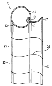
Referring to FIGS. 1-6, a roller shade tube assembly made in accor-
dance with the invention and generally indicated at 11 is described. Tube
assembly 11 comprises a tube 13 made of a metal extrusion such as alumi-
num and having an outside surface around which a fabric shade 23 is selec-
tively wound and unwound. Tube 13 is formed with a arcuate recessed
portion 15 for accommodating an extension wing 17. Extension wing 17 is
to formed with a hinge portion 19 which is pivotally rotatable about a bulb 21
of
recessed portion 15.
In FIG. 1, extension wing 17 is shown in a fully retracted condition and
is fitted over or along recessed portion 15. In FIGS. 2 and 3, extension wing
17 has been pivotally rotated to a substantially fully extended condition
which
enables tube assembly 11 to support fabric shade 23 in an open condition, as
described below.
Referring specifically now to FIGS. 4-6, fabric shade 23 is defined by
an outside sheet 25, an inside sheet 27, and a plurality of fabric slats 29
extending between sheets 25 and 27. As is best shown in FIGS. 5 and 6, the
2 o top end of outside sheet 25 is attached to tube 13 along the surface
thereof,
while the top end of fabric sheet 27 is attached to the tip or end of
extension
wing 17.
When fabric shade 23 is being wound or unwound about roller shade
tube 13, as shown in FIG. 4, extension wing 17 is disposed in a fully
retracted
2s position along recessed portion 15. Just before fabric shade 23 is fully
lowered, extension wing 17 begins to pivotally rotate away from recessed
portion 15, as shown in FIG. 5, thereby causing the separation of sheets 25
and 27 from each other. In FIG. 6, fabric shade 23 is shown in a completely
lowered condition with extension wing 17 fully extended. As a result, fabric
CA 02373251 2001-11-02
WO 01/02688 PCT/US00/14951
-5-
sheets 25 and 27 of shade 23 are fully separated from each other such that
fabric slats 29 are disposed in a perpendicular direction with respect to
sheets
25 and 27. Since slats 29 are made of a light-blocking or light-diffusing
material such as a non-woven or woven polyester, when disposed in a
s perpendicular direction as shown in FIG. 6, light is able to pass through
fabric
sheets 25 and 27 of shade 23.
As can be appreciated, especially from viewing FIG. 6, a smaller
diameter tube may be used to accommodate a fabric shade which, when fully
lowered, has a width substantially greater than the diameter of the tube. This
1 o is because of the use of extension wing 17, as previously described. As a
result, the inventive system may be incorporated into or with a low-profile
headrail, which consumers generally find to be substantially more attractive.
In addition, because a smaller tube (and, in turn, headrail) is needed
when utilizing the invention, less material is needed to produce the tube and
15 headrail, which may reduce product costs.
Furthermore, the inventive roller shade tube reduces the "holding
strength" required to hold the fabric shade in place, thereby creating a
lighter
feel for operation. In other words, a lower weight clutch unit may be used
because the roller shade tube diameter has been substantially reduced. This
2 o is because a smaller diameter tube requires the clutch or brake mechanism
to
supply less torque in order to support the same size shade.
Referring now to FIG. 7, a second embodiment of the roller shade tube
assembly is described and generally indicated at 11'. Assembly 11' com-
prises a tube 13' having an arcuate recessed portion 15' for accommodating
2 s wing 17'. Wing 17' is formed with a hinge portion 19' pivotally rotatable
about a bulb 21' of recessed portion 15', as described before. Significantly,
wing 17' of assembly 11' comprises a series of arcuate segments 31 made
preferably from aluminum or molded plastic and each formed with two under-
lying slots 33 and 35. A stiffener element 32 preferably made of polycar-
3 o bonate material or aluminum, (similar to a Venetian blind slat) is
received
CA 02373251 2001-11-02
WO 01/02688 PCT/US00/14951
-6-
within slots 33 and 35 of segments 31 and runs the entire length of tube 13:
Assembly 11' is particularly suitable when the tube thereof is long in
dimension, as it aids assembly and eliminates potential friction and binding
between the tube and the wing assembly.
s It will thus be seen that the objects set.forth above, among those made
apparent from the preceding description, are efficiently attained. Certain
changes may be made in the invention without departing from the spirit and
scope thereof. It is further noted that the scope of protection is set forth
in the
claims.
to