Note: Descriptions are shown in the official language in which they were submitted.
CA 02373803 2007-05-01
77060-18
- 1 -
ceal;=c Rcll,e= ?sc. Seal~rc Rollu- Fle.-aent
Partict 3a~ 1 r Fe= ~roct cinc t Tata=cr_ Foc F~~zire F3vc=ene
.Fir.d Met'~od T~iere=o_
Field of the Iavention
The invention relates to a sealing rnller,
particularly for a device for producing a tampon f:cr
feminine hygiene as well as a method for producing a
tarrmon.
~e
BackQround of the Inventioa
Friese, US Pat. No. 4,816,100 discloses a method
and a device -Lzc= preducinc a tamno:i fcr the ferr1.inine
hygiAne. The me}hod. inC~.Ldes sectior_=ng a;luid
CA 02373803 2001-12-28
WO 01/01903
PCT/EP00/06134
- 2 -
permeable and at least partially thermoplastic material
and heat sealing it onto an absorbent nonwoven fiber
material or fleece web. Individual sections of the
absorbent are severed from the fleece web supply and are
wound onto themselves to form a tampon blank having a
withdrawal cord. Thereby the fluid permeable cover
material is positioned on the circumference of the
tampon blank and surrounds it essentially completely.
Finally, the tampon blank is pressed radially into the
final shape of the tampon. Friese also employs a
sealing roller to heat sealing the cover material onto
the fleece web or the fleece web section. The sealing
roller of Friese comprises heatable sealing elements
that are spaced apart around the circumference of the
is sealing roller. Insulating means are arranged between
these sealing elements. Thus, the sealing roller
sealing elements and insulating elements alternate about
the surface of the sealing roller in the direction of
rotation.
Wilkes et al., US Pat. No. 5,634,914, discloses
multilimbed regenerated cellulose fibers which patentee
claims provide high absorbency and a cotton-like handle.
These tampons are described as having good stability
and absorbency. Longitudinally-expanding tampons having
these fibers are described as having less expansion than
conventional longitudinally-expanding tampons.
Finally, Nguyen et al., w097/23185 discloses
tampons that can expand in the presence of high humidity
CA 02373803 2001-12-28
WO 01/01903
PCT/EP00/06134
- 3 -
after insertion into a user's body to prevent early
bypass leakage from occurring. This tampon is a
substantially cylindrical mass of compressed fibers
enclosed within a fluid-permeable cover. The tampon has
a stability of at least about 15 N, and is capable of
radially expanding upon exposure to a humid environment.
The radius increases by at least about 10% after 15
minutes to 90% relative humidity at 40 C. Particularly
useful in this tampon are multilimbed fibes such as
io those in Wilkes et al. These fibers are relatively
stiff to help the early expansion of the tampons.
Unfortunately processing these fibers causes
difficulty, especially when a fibrous web having stiff
fibers, such as the multilimbed fibers of Wilkes, are
exposed to unexpected or undesired delays during
manufacture. Such delays can allow previously
calendered or compressed fibrous webs to bloom or
expand, possibly due to humidity, as described in Nguyen
et al. This expansion can cause jams or other
undesirable process interruption.
Therefore, what is needed is a device and process
to produce a high-quality tampon that secures a
sufficient calendering of the fibrous fleece web for
fibers that are otherwise hard to maintain in a
compressed condition at a low cost.
CA 02373803 2001-12-28
WO 01/01903
PCT/EP00/06134
- 4 -
Su=aary of the Invention
An apparatus for thermally bonding a cover material
onto an absorbent, fibrous web has a substantially
cylindrical, rotatable sealing roller and a rotatable
s anvil roller disposed adjacent the sealing roller to
provide a nip therebetween. The cover material and
.fibrous web can be sealed and calendered in the nip of
this apparatus. The sealing roller includes a sealing
element and an ironing element, and both of these
elements have thermally conductive material and a
leading and a trailing end in the direction of rotation.
The sealing roller has at least one pair of sealing and
ironing elements positioned sequentially on the
circumferential surface of the sealing roller in the
direction of rotation. At least one end of the ironing
element is thermally insulated from an adjacent end of
an adjacent sealing element.
The process for producing a tampon includes the
following steps: a) applying a cover sheet to a fibrous
web; b) passing the fibrous web and cover sheet
combination through the nip of a sealing roller and an
anvil roller; c) applying heat to a first portion of the
combination at a first temperature range sufficient to
bond the cover sheet to the absorbent web; and d)
applying heat to a second portion of the combination at
a second temperature range insufficient to bond the
cover sheet to the absorbent web and sufficient to
calendar the fibrous web. The sealing roller provides
WO 01/01903 CA 02373803 2001-12-28
PCT/EP00/06134
- 5 -
heat at both the first and second temperature ranges to
the cover sheet and fibrous web combination.
Again, it is an object of the invention to provide
a device and a process to produce a high-quality tampon
that secures a sufficient calendering of the fibrous
fleece web for fibers that are otherwise hard to
maintain in a compressed condition at a low cost device
for producing a high-quality tampon which secures a
sufficient cal.enderinq of the fleece web for fibers
which are hard to calender at low cost. This object is
solved by the apparatus including the sealing roller and
the process of the present invention.
Brief Description of the Invention
Fig. 1 shows diagrammatically in cross-section an
embodiment of the inventive sealing roller.
Fig. 2 shows in an perspective view another
embodiment of an inventive sealing roller and a fleece
web section with cover material sealed onto it.
Detailed Description of the Preferred Embodisnetnt
In order to form the fleece web into the desired
fleece thickness and fleece intensity, the fleece web
usually is calendered, i.e., pressure and temperature
are applied to it. Depending from the kind of fibers
used for the fleece web, it turned out to be problematic
that the fleece web is not sufficiently treated by
standard calenderinq so that only a "subcalendering"
CA 02373803 2001-12-28
WO 01/01903
PCT/EP00/06134
- 6 -
takes place. In order to achieve the desired fleece
thickness and intensity of the fleece web, some fibers,
especially the fibers which are preferred because of
their higher absorptive capacity, require several
s calendering steps which in the production process is
complicated and, thus, expensive.
According to the invention, the sealing roller
having at least one sealing element located at the
circumference of the sealing roller comprises at least
one heatable ironing element consisting of thermally
conducting material that is thermally separated at at
least one end from at least one adjacent sealing
element. "Thermally separated" in this case means that
there is essentially no, or in comparison with the
relevant heating energies or energy differences, no
considerable heat transport between the elements, so
that the elements are at least largely insulated against
each other.
Thus, it is achieved that pressure and temperature
are applied to the fleece web at its entire length by
the sealing roller. In addition to the original object
of the sealing roller, namely the sealing of cover
material onto the fleece web, the fleece web is ironed
and calendered without requiring a further process step
or an additional device for the already complex and
expensive processes or process machines, respectively.
Even hard to calendar fibers are reliably and durably
CA 02373803 2007-05-01
77060-18
- 7 -
orrned th= des;retd s:ape by t:e r _peated _rc _inc cr
calende;:.nc resoeczivel y.
The f.ieece weh rnay include any abso,bent mater-=_'_s
ttl: t are caoa7D le c:E ab so_bi nCT an d/c= Z'etr._:~_inG 1=C_.:dJ
(e.(=. , menses) . The abscrbe_~.t strl-'cture can be
manufactured in a wi de variety of sizes and shaoes and
from a wid.e variety of Zicr:id-abscrbing mater_als_ A
representative, n on-i imit4.ng ? i st o= useLUl materials
includes ,cellu=osic materials, such as rayon, cottor,
wood pulp, creped cellulose wadding, tissue wraps and
laminates, p eat moss, and chem=cally st_ff ened,
modified, er c,oss-linked celiulesic fibers; polymer:c
mater:.aZs, such as polvester fibers, pnlyole'_':.'1 i1Ae:s,
absorbent foams, a~.,'lserber_t spor.ges, sutnerabso=bent
:.s polymers, absorbe::t geiling materials; formed fibers,
such as cap illary c:~=_r.nel fiber9 and multilimbed fibers;
combinations of materials, such as synthetic fibers anc
wood pulp including cof onned f ibrous structures ( e. g.,
those mate rials described in A~.Zderson et al., U.S.
Patent No. 4,100,324); or any eGuivalent material cr
combinations of materials, or mixtures of these.
Nowever, the present invention is particularly useful
for processing fleece webs containing multilimbed
fibers, such as those disclosed in Wilkes, US Pat. No.
5,63a,91t.
Useful cover materials used in conjunction with the
present invention will be recognized by the crd;narily
CA 02373803 2007-05-01
77060-18
- 8 -
skilled practitioner. Known cover materials include woven,
knit, and nonwoven fabrics; two-dimensional and three-
dimensional apertured films; polymeric nets; and the like.
Preferably, the cover material is a nonwoven fabric or a
three-dimensional apertured film. Such nonwoven materials
are disclosed in Friese, US Pat. No. 4,816,100. In
addition, the apertured film cover of the present invention
can be manufactured by standard processes known to those of
ordinary skill in the art. For example, the base film that
is to be apertrued can be extruded, cast, or blown to form
the film. The base film can be a single formulated
polymeric material or blend, or it can be a laminated or
multi-layered material such as described in commonly
assigned, US Patent Publication 2003-0093049A1. Useful
technology to form these films will be easily recognized by
those of ordinary skill in the art. The based film can then
be apertured by any useful process. Several examples
include hot air aperturing, and water jet aperturing.
Examples of these processes are disclosed in Curro, US Pat.
No. 4,695,422; Turi, US Pat. No. 5,567,376; and Mullane, US
Pat. No. 4,741,877. The resulting apertured film can be
coated, for example
CA 02373803 2007-05-01
77060-18
~
as described in commonly assigned,
PCT Patent Publication WO 01/01905 Al,
2.999, entitled "Tam:,cr_ w-;Lt = Cover and. Nonio nic
S,urfactart" (Aztcz-ney Doc:cet P:C-708) , and/or slit to a
desired w;dth ;or use in rr,a, uracturi:lc a tamaon.
T1-1 a pra.re__ed eml7oCi.ment, the rear end of the at
i e'c.s'. Cne 1.roP.=nc element, as seen fz:m t?--,e rotct=nc
C1 reCtiC'_'i of the se'c.? _: C roiler, is 1n therTic.l contact
w_th the seali. c element posit;or.ed behind the ircr.in g
2.0 element in the rotatina direction and the front end in
the _ ct :*_ing directi cn c= the at least one i-on inc
element is separated =rorn the heatable sealing element
which is located in front of the.ironinc element when
seen f'rom the c.:rection of rotation. Tzus, the ircl_ing
1.5 element is heated ind:.rectly via the trermal contact of
the seflinc element. An additional heating device for
the :.ronir_c elemer_t is not reaui red. Moreover, the
temperature cf the ironing element is automatically
aciapted to the desi red terroerature predetermined or
20 recrt:ired for the heat sez? ing. The temperature appli.eci
to the fleece web slowly decreases from the highest
temroeratur e at the sealing element adjacent an
insulatincr element or snace to the front end of the
_roning element and finally to the rear end of the
:25 ironing element to constantly calender the fleece web.
It i9 adCitionally guaranteed that a maximum
temperature of the ironing element is not exceeded in
the area in which a heat sealinc, of t.-.e cover material
CA 02373803 2001-12-28
WO O1/01903
PCT/EP00/06134
- 10 -
is to be prevented. An undesirable heat sealing of the
cover material onto the fleece web is prevented and at
the same time the fleece web material is ironed and
calendered whereby a remarkably improved fiber structure
of the fleece web is achieved.
The material of the ironing element may be chosen
from numerous thermally conducting materials. In
general, metals, in particular aluminum, are the
preferred materials. Depending on the choice of
io material and the corresponding heat conductivity, the
course of temperature or the temperature gradient
respectively may be determined in case of an above--
mentioned partial thermal contact and optimally adapted
to the material in use of either the fleece web and the
1.s cover material.
The thermally separated ends of the ironing element
and the sealing element are preferably spaced apart in a
predetermined distance so that an insulating air
aperture is formed. it is also possible to place an
20 insulating element between the thermally separated
elements. Preferably, the sealing element and the
ironing element are not completely thermally separated.
However, the desired level of insulation may be
determined in relation to the chosen spaces between the
zs elements or the applied insulating elements. The heat
conductivity or the heat contact respectively of the
ends of the ironing element and the sealing element
being in thermal contact may considerably be improved if
CA 02373803 2001-12-28
WO 01/01903
PCT/EP00/06134
- 11 -
the ironing element and the sealing element at least
partially overlap and/or are at least partially
interlocked. The overlapping may be realized wherein
the end portion of the sealing element is graded or
inclined and is located below or above a correspondingly
formed end portion of the ironing element and is engaged
with it. This overlapping may also be regarded and
desicnated as a "radial interlocking". A second
possibility is an at least partial interlocking of both
elements at the outer surface, in general in a coaxial
rotating direction of the sealing roller.
In a preferred embodiment, the sealing roller
comprises two diametrically opposed sealing elements and
two diametrically opposed ironing elements. This
is results for usual lengths of the cover material, which
is applied in the form of strips of the fleece web
section, respectively, in a simple and easy-to-realize
geometry and dimension of the sealing roller. Thus, the
desired geometrical arrangement of the ironing elements
and the sealing elements is secured without requiring a
great curvature of the surfaces of the elements
resulting from a sealing roller having a small diameter.
Naturally, it is possible to arrange only one sealing
element and one ironing element or more than two sealing
elements and two ironing elements alternately. The
dimension of the sealing roller increases with the
number of sealing and ironing elements provided for,
since the circumferential length of the single elements
CA 02373803 2001-12-28
WO Ol/01903
PCT/EP00/06134
- 12 -
depend from the geometry of the materials to be treated,
the cover material and the fleece web section, as
explained above.
Preferably, the temperature of the sealing elements
is adjustable by a control to allow adjustment of the
sealing element temperature to maintain it at a desired
target temperature. Appropriate thermal sensors may be
used to monitor the temperature. The adjustable
temperature control allows the device to be adapted to
the materials to be processed, so that a variety of
fibers and cover materials such as those materials
described above may be processed in a high quality
manner.
In another embodiment, in addition to the sealing
is elements, the ironing elements are directly heatable.
Thus, further possibilities for the temperature control
of the ironing elements exist, the ironing elements
especially have a constant temperature without any
temperature gradient along their entire area in care
this is desired for the final product to be processed.
In such an embodiment, it is likely that both ends of
each ironing element are thermally separated from
adjacent sealing elements.
The invention further relates to a method for
producing a tampon for feminine hygiene. In particular,
it relates to a method involving thermally sealing an at
least partially thermoplastic cover material to a fleece
web at a desired sealing temperature. The method
CA 02373803 2001-12-28
WO 01/01903 PCT/EP00/06134
- 13 -
according to the invention also provides for ironing the
fleece web at an ironing temperature at a location
between the areas of the cover material that are sealed
whereby the maximum ironing temperature does not exceed
s the sealing temperature. In the areas in which the
ironing element works on the cover material, the ironing
temperature should not be high enough to cause
unintentional sealing or damage to the cover material.
As described above in connection with the device
according to the invention, by such method, the fleece
web is at the same time calendered over its surface by
the required sealing process, i.e., pressure and
temperature are applied. The desired fleece web
structure and fleece web thickness is secured without
the requirement of a new process station and additional
devices.
The preferred sealing temperature is 140 C for the
preferred fleece web containing cotton and rayon or
rayon blends and a cover material containing
polyethylene. This provides a reliable heat sealing of
the materials in use. The cover material is reliably
bonded with the fleece web section in the desired bond
region while the rest of the cover material attains a
temperature that does not cause it to bond or otherwise
be damaged.
In another embodiment of the method according to
the invention, the ironing temperature is essentially
constant which is preferably realized by a separate
CA 02373803 2001-12-28
WO O1/01903
PCT/EPOO/06134
- 14 -
heating of the ironing element. With this method, one
end of the ironing element may be in thermal contact
with the sealing element leadina at least in a partial
area of the ironing element to a temperature gradient or
the sealing element may be thermally completely
separated, the latter being the preferred variation.
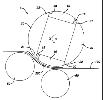
Fig. 1 shows an embodiment of an inventive sealing
roller 1 having two sealing elements 10 arranged
diametrically facing each other and two ironing elements
20 arranged between the sealing elements 10, said
ironing elements 20 diametrically facing each other.
The circumferential length of the sealing elements 10
corresponds exactly to the length of a range of a fleece
web i00 to be sealed onto the cover material 200.
ls The sealing elements 10 as well as the ironing
elements 20 are made of a thermally conductive material.
A representative, non-limiting list of materials
includes metals such as steel, including stainless
steel, mild steel, tool steel, and the like; and
aluminum. Useful stainless steels include the 300
series including 303, 304, and 316; the 400 series, and
the 800 series. Useful mild steels include 1018 and
1020. Useful aluminum alloys include the 2000 series
including 2024; the 3000 series including 3003; the 5000
series including 5052 and 5080; the 6000 series
including 6061, 6063, and 6082; and the 7000 series
including 7075. These materials can be coated with
appropriate coatings to protect the sealing element from
CA 02373803 2001-12-28
WO 01/01903 PCT/EP00/06134
- 15 -
corrosion and wear and to reduce the likelihood of the
sealed material from adhering to the tooling surfaces.
Such materials will be recognized by those of ordinary
skil:. in the art.
s Heating elements are associated with the sealing
elements 10 in a manner to provide well-controlled heat
to the sealing bars 16. Preferably, the heating
elements controllable to provide a heat accuracy of +/-
C, more preferably, about +/- 20 C. This can be
achieved by placing, e.g., two heating elements
symmetric to a middle plane of the sealing element 10,
or three or more elements in appropriate locations on
the sealing element. Alternatively, it is possible to
employ a single plate heating element or to incorporate
is conduits within the sealing element 10 to accommodate a
circulated heating fluid. In addition, a temperature
control element, such as a thermocouple, can be provided
close to the sealing surfaces, e.g., at the middle plane
of the sealing element 10.
The ends 22 of the ironing elements 20 which, in
the direction of rotation of sealing roller 1, marked by
arrow x, are positioned at the rear end, are in thermal
contact with each sealing element 10 positioned back of
it. The ends of the ironing elements 20 being the front
ends 21 in the direction of rotation are thermally
separated from each sealing element 10 positioned in
front of it. The thermal separation can be simply
realized by an air gap. In the current embodiment,
CA 02373803 2001-12-28
WO 01/01903 PCT/EP00/06134
- 16 -
however, the use of a high heat insulating plastic
element 15 is intended.
In operaticn the sealing elements 10 are heated up
to a temperature of 140 C. Via a thermal contact 30
s heat energy is transferred from the sealing element 10.
to the ironing element 20 so that each ironing element
20 has also a temperature of 140 C at its rear end in
close proximity to the thermal contact 30. The ironing
elements 20 show a temperature gradient because of the
existing cooling so that in the current embodiment there
is a temperature of about 800 C at a front end 21 of
each of the ironing elements 20 being separated from the
sealing element 10 next to it by the insulating elements
15.
is A pressure roller 50 presses the fleece web 100
against the sealing roller so that the cover material
200 is securely sealed onto the fleece web by sealing
elements 10. Furthermore, it is provided for another
transport and/or driving roller 60 that drives the
fleece web 100 and/or holds it in the desired position.
Fig. 2 shows a perspective view of a further
embcdiment of an inventive sealing roller as well as a
fleece web auction 105 with a strip of cover material
200 sealed onto it. The sealing elements 10 comprise
sealing bars 16 arranged in transverse rows and at
distances from one another with said sealing bars
projecting about 0.3 cm from a base 17 of the sealing
elements 10.
CA 02373803 2001-12-28
WO 01/01903 PCT/EP00/06134
- 17 -
The ironing elements 20 are not shown in Fig. 2,
they merely consist of circle segments with a
substantially smooth but curved surface which can be
inserted into the sealing roller 1. By a possible
s exchange of the ironing elements 20 the temperature and
especially the temperature gradient of the ironing
elements can be adapted to the desired object and the
used materials, respectively in dependence on the
material and its thermal conductivity. As shown in the
embodiment of Fig. 1, the thermal contact is provided
for between the ends being the rear ends of the ironing
elements 20 in the direction of rotation x and the
respective sealing elements 10 positioned back of it
whereas the ends being the front ends 21 of the ironing
is elements 20 in the direction of rotation x are separated
from the respective sealing elements 10 positioned in
front of it after the ironing elements having boon
inserted into the sealing roller 1.
It is again to be stated that in the scope of the
invention further variations of the sealinq bars are
possible and applicable. In addition to sealing the
cover to the fleece web, the sealing bars 16 of the
sealing element 10 can extend beyond the cover material
to additional compress or calender the fleece web. This
provides further beneficial calendering to stiff fibers
that may be included in the fleece web.
CA 02373803 2001-12-28
WO 01/01903 PCT/EP00/06134
- 18 -
The drawings are merely diagrammatical and not in
the real ratio of dimensions so that no limitations can
be deducted from the concrete dimensions.
The features disclosed in claims, specification and
s drawings can be substantial for the invention, either
solely or in any possible combination.