Language selection

Search

Patent 2373839 Summary

Third-party information liability

Some of the information on this Web page has been provided by external sources. The Government of Canada is not responsible for the accuracy, reliability or currency of the information supplied by external sources. Users wishing to rely upon this information should consult directly with the source of the information. Content provided by external sources is not subject to official languages, privacy and accessibility requirements.

Claims and Abstract availability

Any discrepancies in the text and image of the Claims and Abstract are due to differing posting times. Text of the Claims and Abstract are posted:

  • At the time the application is open to public inspection;
  • At the time of issue of the patent (grant).
(12) Patent Application: (11) CA 2373839
(54) English Title: DEVICE FOR APPLYING SPATIALLY LIMITED ELEMENTS, IN PARTICULAR, FLEXIBLE ELEMENTS
(54) French Title: DISPOSITIF POUR APPLIQUER DES ELEMENTS DELIMITES SPATIALEMENT, EN PARTICULIER SOUPLES
Status: Dead
Bibliographic Data
(51) International Patent Classification (IPC):
  • B65H 20/30 (2006.01)
  • B65H 20/24 (2006.01)
  • B65H 39/14 (2006.01)
  • B65H 39/16 (2006.01)
(72) Inventors :
  • WITTMAIER, KLAUS (Germany)
(73) Owners :
  • SCHOBER GMBH WERKZEUG- UND MASCHINENBAU (Germany)
(71) Applicants :
  • SCHOBER GMBH WERKZEUG- UND MASCHINENBAU (Germany)
(74) Agent: GOWLING LAFLEUR HENDERSON LLP
(74) Associate agent:
(45) Issued:
(86) PCT Filing Date: 2000-04-12
(87) Open to Public Inspection: 2000-11-02
Availability of licence: N/A
(25) Language of filing: English

Patent Cooperation Treaty (PCT): Yes
(86) PCT Filing Number: PCT/EP2000/003271
(87) International Publication Number: WO2000/064794
(85) National Entry: 2001-11-13

(30) Application Priority Data:
Application No. Country/Territory Date
199 18 429.1 Germany 1999-04-23

Abstracts

English Abstract


The invention relates to a device for applying spatially limited, flexible
elements (26), to a continuous web (14), in particular for applying holograms.
The speed of the continuous web (14) is reduced in the application zone and
the flexible element is applied at this time.


French Abstract

Dispositif pour l'application d'éléments (26) souples, délimités spatialement, en particulier d'hologrammes sur une bande continue (14), cette dernière étant ralentie dans la zone d'application et l'élément souple étant appliqué à ce moment là.

Claims

Note: Claims are shown in the official language in which they were submitted.


1. Device for the application of spatially limited, in
particular flexible elements, e.g. holograms or the like,
onto a first continuous web (14), wherein the elements are
removed from a supply roll, transported via a sealing
station (20) to a removal or guiding station (12), wherein
the flexible element is applied onto the continuous web
(14) at the sealing station (20), wherein one acceleration
or deceleration station is provided before and one after
the sealing station (20) through which the first continuous
web (14) passes, thereby lowering the speed of the
continuous web (14) to a non-zero speed of a second
continuous web (26) having the flexible elements.
2. Device according to claim 1, characterized in that the
acceleration or deceleration station is an eccentric
station (18,22) and the eccentric station (18,22) comprises
an eccentric shaft (34,36) via which the first continuous
web (14) is guided, wherein the two eccentric shafts
(34,36) rotate, mutually offset by 180°.
3. Device according to claim 2, characterized in that the
eccentric shafts (34,36) rotate in the transport direction
of the first continuous web (14).


2
4. Device according to any one of the claims 2 or 3,
characterized in that the eccentric shafts (34,36) have a
circular cross-section and are eccentrically mounted.
5. Device according to any one of the claims 2 through 4,
characterized in that the outer periphery of the eccentric
shafts (34,36) comprises a sleeve which can rotate relative
thereto.
6. Device according to any one of the claims 2 through 5,
characterized in that the eccentricity of the eccentric
shafts (34,36) can be adjusted.
7. Device according to any one of the claims 2 through 6,
characterized in that the eccentric shafts (34,36) rotate
synchronously with respect to the application cycle.
8. Device according to any one of the claims 2 through 7,
characterized in that the continuous web (14) is
continuously removed from the supply roll, wherein the
first continuous web (14) has a transport speed which can
be changed in the region of the sealing station (20), in
particular decelerated and accelerated, by means of the
eccentric shafts (34,36).
9. Device according to any one of the preceding claims,
characterized in that application occurs in the sealing
station (20) when the first continuous web (14) has its
minimum speed.


3
10. Device according to any one of the preceding claims,
characterized in that the second continuous web (26) has a
speed which corresponds to the minimum speed of the first
continuous web (14).
11. Device according to any one of the preceding claims,
characterized in that the sealing station (20) is a heat
sealing station, stamping station, gluing station,
fastening station or the like.

Description

Note: Descriptions are shown in the official language in which they were submitted.


CA 02373839 2001-11-13
a
Translation of PCT/EP00/03271 as filed on April 12, 2000
Device for Applying Spatially Limited Elements, in Particular,
Flexible Elements
Description
The invention concerns a device for applying spatially limited
elements, in particular, flexible elements, e.g. holograms or
the like, to a continuous web which is removed from a supply
roll and transported via a sealing station to a removal or
guiding station, wherein the flexible element is applied to
the continuous web in the sealing station.
Conventionally, cards, notes, paper sheets or the like are
produced by initial processing of a continuous web through
printing, punching, stamping etc., and finally cutting or
punching out the individual products from the continuous web.
Also conventionally, the individual products are provided with
spatially limited elements, e.g. images or very expensive
holograms and the like. These spatially limited elements are
also disposed on a continuous web from which they are removed
for disposal on the first continuous web. If the two
continuous webs move through the sealing station at the same
speed, only a fraction of the second continuous web is used
and the major part of the second continuous web must be
disposed of as waste, since the spatially limited element is


CA 02373839 2001-11-13
2
substantially smaller than the products onto which they are to
be applied. The intermediate spaces between the individual
spatially limited elements on the second continuous web
therefore constitute waste.
It is consequently the underlying purpose of the present
invention to provide a device which improves utilization of
the second continuous web to reduce waste.
This object is achieved in accordance with the invention in
that, in a device of the above-mentioned type, two eccentric
stations are provided, one before and one after the sealing
station, wherein each eccentric station comprises an eccentric
shaft via which the continuous web is guided, wherein the two
eccentric .shafts circulate, mutually offset by 180°.
Provision of an eccentric station before and after the sealing
station through which the continuous web is guided permits
deceleration and acceleration of the transport speed of the
material web in these eccentric stations, which therefore act
as a temporary buffer. This is effected by the eccentric
shafts via which the continuous web is guided. As the
eccentric shafts turn, they gather and subsequently release
the continuous web during eccentric deflection. A sinusoidal
reciprocating motion is thereby superimposed on the transport
speed of the continuous web such that the resulting transport
speed has slow and fast travel.


CA 02373839 2001-11-13
3
If the spatially limited element, e.g. the hologram is also
located on a continuous web, the hologram is applied to the
first continuous web, when the latter moves at its minimum
transport speed. The continuous web carrying the holograms
must therefore only be transported at this minimum transport
speed and the waste between the individual holograms is
accordingly reduced. After application of the hologram to the
first continuous web, the latter is accelerated again to its
maximum speed and subsequently decelerated for applying the
next hologram.
The eccentric shafts preferably move in the transport
direction of the continuous web thereby minimizing the
relative speed and therefore the friction between eccentric
shaft and the continuous web.
In a preferred embodiment, the eccentric shafts have a
circular cross-section and are eccentrically mounted. A
circular cross-section of the eccentric shaft advantageously
has, in contrast to a cam-shaped eccentric shaft, a protective
effect on the continuous web since the forces of the eccentric
shaft acting on it increase and decrease in a sinusoidal
fashion, thereby avoiding abrupt force peaks.
The frictional forces are reduced by disposing a sleeve on the
eccentric shaft which can rotate with respect to the eccentric
shaft and which has zero speed relative to the transported
web.


CA 02373839 2001-11-13
4
In accordance with a preferred embodiment, the eccentricity of
the eccentric shafts can be adjusted. The amplitude of the
sinusoidal acceleration or deceleration can thereby be
adjusted to a desired value.
In a further development, the eccentric shafts circulate
synchronously with the application cycle. Every time sealing
is to be effected, the continuous web moves at a minimum
transport speed. This facilitates precise sealing and, during
application, the first continuous web also has the same speed
as the second continuous web from which the hologram is
removed.
Further advantages, features and details of the invention can
be extracted from the dependent claims and the following
detailed description of a particularly preferred embodiment,
with reference to the drawing. The features shown in the
drawing and mentioned in the description and in the claims may
be essential to the invention either individually or
collectively in any arbitrary combination.
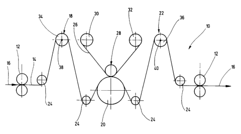
The drawing shows ~a basic view of the inventive device 10. A
continuous web 14 is removed from a supply roll (not shown)
via a removal station 12 in the direction of the arrow 16.
This continuous web 14 initially passes a first eccentric
station 18 and is then guided into a sealing station 20. After
the sealing station 20, it is guided via a second eccentric
station 22 and transported by an additional removal station


CA 02373839 2001-11-13
12. Reference numeral 24 designates deflection or compensating
rollers.
A hologram from a hologram foil 26 is applied to the
continuous web 14 in the sealing station 22. This is effected
via a stamping field which is provided on a sealing roller 28.
The hologram foil 26 is optionally removed from a supply roll
30 via a transport device (not shown) and wound onto a winding
roller 32.
Each of the two eccentric stations 18 and 22 has an eccentric
shaft 34 and 36 which rotate about an axis 38 and 40,
respectively. The two eccentric shafts 34 and 36 are mutually
offset by 180°.
The two eccentric shafts 34 and 36 rotate synchronously such
that the mutual 180° offset remains constant. The rotational
speed corresponds to the transport speed of the continuous web
14 and is adjusted such that a product located on the
continuous web 14 rotates once about each of the two eccentric
shafts 34 and 36. This means that the section of the
continuous web l4~is decelerated once and is accelerated once
between the two eccentric stations 18 and 22, for each product
passing the sealing station 20.
The transport speed of the hologram foil 26 is thereby set to
correspond to the minimum transport speed of the section of
the continuous web 14 located between the eccentric stations
18 and 22, wherein the hologram is applied at the time of


CA 02373839 2001-11-13
6
minimum transport speed. At precisely this point in time, the
hologram disposed on the hologram foil 26 is exactly in the
desired position on the continuous web 14. This is achieved by
means of a register control, e.g. the hologram foil 26
comprises a register perforation into which corresponding
transport pins, register pins, or the sealing roller 28
engage. After application of the hologram to the continuous
web 14, the continuous web 14 is accelerated, while the speed
of the hologram foil 26 remains constant. In this fashion, the
separation between the individual holograms is reduced such
that the hologram foil 26 can be better utilized and waste is
minimized.

Representative Drawing
A single figure which represents the drawing illustrating the invention.
Administrative Status

For a clearer understanding of the status of the application/patent presented on this page, the site Disclaimer , as well as the definitions for Patent , Administrative Status , Maintenance Fee  and Payment History  should be consulted.

Administrative Status

Title Date
Forecasted Issue Date Unavailable
(86) PCT Filing Date 2000-04-12
(87) PCT Publication Date 2000-11-02
(85) National Entry 2001-11-13
Dead Application 2005-04-12

Abandonment History

Abandonment Date Reason Reinstatement Date
2004-04-13 FAILURE TO PAY APPLICATION MAINTENANCE FEE

Payment History

Fee Type Anniversary Year Due Date Amount Paid Paid Date
Registration of a document - section 124 $100.00 2001-11-13
Reinstatement of rights $200.00 2001-11-13
Application Fee $300.00 2001-11-13
Maintenance Fee - Application - New Act 2 2002-04-12 $100.00 2002-03-25
Maintenance Fee - Application - New Act 3 2003-04-14 $100.00 2003-03-20
Owners on Record

Note: Records showing the ownership history in alphabetical order.

Current Owners on Record
SCHOBER GMBH WERKZEUG- UND MASCHINENBAU
Past Owners on Record
WITTMAIER, KLAUS
Past Owners that do not appear in the "Owners on Record" listing will appear in other documentation within the application.
Documents

To view selected files, please enter reCAPTCHA code :


To view images, click a link in the Document Description column. To download the documents, select one or more checkboxes in the first column and then click the "Download Selected in PDF format (Zip Archive)" or the "Download Selected as Single PDF" button.

List of published and non-published patent-specific documents on the CPD .

If you have any difficulty accessing content, you can call the Client Service Centre at 1-866-997-1936 or send them an e-mail at CIPO Client Service Centre.


Document
Description 
Date
(yyyy-mm-dd) 
Number of pages   Size of Image (KB) 
Description 2001-11-13 6 218
Representative Drawing 2002-05-03 1 7
Abstract 2001-11-13 1 10
Claims 2001-11-13 3 84
Drawings 2001-11-13 1 14
Cover Page 2002-05-06 1 34
PCT 2001-11-13 16 604
Assignment 2001-11-13 5 156
Correspondence 2002-05-01 1 15
Assignment 2002-01-24 3 104
Fees 2003-03-20 1 34
Fees 2002-03-25 1 35