Note: Descriptions are shown in the official language in which they were submitted.
CA 02374280 2002-03-04
Power System Management Method and Power System
Management System
Background of the Invention
1. Technical Field
The present invention relates to a power system
management method and to a power system management
system for changing a function of equipment control
apparatus, in a power system comprising an equipment
control apparatus provided on the side of facility
equipments constituting the power system and
controlling the mentioned facility equipments, and a
monitoring control apparatus provided outside of the
mentioned equipment control apparatus and receiving
internal information about the mentioned equipment
control apparatus via a web communication net thereby
monitoring states of the mentioned power system on the
basis of the mentioned internal information.
2. Background Art
Hitherto, management of a power system has been
carried out in the following manner. For example, any
maintenance man who opens a relay board and inspecting
it conducts maintenance of the relay board. Also, a
relay board manufacturer directly setting and
operating the relay board conducts setting change of
a relay and the like accompanied with change and
expansion of a scale of the system.
It is a recent trend that, engineering
developments have been increasing in the direction of
1
CA 02374280 2004-09-23
carrying out power system management such as
maintenance monitoring, setting change and the like by
means of a remote electronic terminal employing a Web.
One of such examples is described in the specification
of the Japanese Patent Application No.199262/2000
(Japanese Patent Pub lication (unexamined) No. 2001-
333549 laid-open on November 30, 2001) filed by the
applicant in Japan on June 30, 2000.
Fig. 9 is a schematic view shown in relation to
the specification of the Japanese Patent Application
No. 199262/2000, and which shows a system concept. In
this system, the relay board is accessed via a Web
communication net from the electronic terminal on the
side of supplying a product such as facility equipments
constituting the power system and a protection control
apparatus protecting and controlling the facility
equipments. Then, the maintenance monitoring and
change in relay setting is carried out from the
electronic terminal on the side of power supply and the
electronic terminal on the side of supplying the
facility equipments constitutingthe powersystem. As
a result of the mentioned system constitution, the
maintenance monitoring and the setting change are
efficiently performed on a display screen from a remote
place.
It is certain that, in such a system, the relay
board is accessed via the Web communication net from
the electronic terminal on the side of the power supply
and the electronic terminal on the side of the product
supply, and further the power system management such
as maintenance monitoring, relay setting change,
writing of a relay function program or the like is
2
CA 02374280 2002-03-04
carried out from the electronic terminal on the side
of the power supply and the electronic terminal on the
side of the product supply, whereby the management such
as maintenance monitoring or setting change can be
efficiently carried out on the display screen from a
remote place. But it is possible that the electronic
terminal is commonly used by both of the persons in
charge of maintenance monitoring and relay setting
change, and the persons in charge of the other work.
Further, it is possible for those other persons to
easily access to any electronic terminal in the case
of being on the Web communication net. As a result,
there is a possibility that any other persons not in
charge of the maintenance monitoring and the relay
setting change may unwillingly change the relay setting
due to simple key manipulation mistake and the like.
Moreover, it is possible that any information regarding
the power system state be changed, which may lead to
a significant problem or accident in terms of system
operation.
Summary of the Invention
The present invention was made to solve such
undesirable problems, and has an object of providing
a power system management method and a power system
management system capable of preventing devices such
as relay from being easily changed in setting due to
manipulation mistake or the like on a display screen
of an electronic terminal by the persons not in charge
of maintenance monitoring and relay setting change, or
3
CA 02374280 2002-03-04
from being changed in information about the power
system state . That is, an obj ect of the invention is
not to bring the power system into any undesirable
management state.
A power system management method according to the
invention comprises a step of changing function of an
equipment control apparatus from outside of the
mentioned equipment control apparatus by means of a
communication method of higher security than that of
a monitoring system operating via a Web communication
net:
said equipment control apparatus being provided
on the side of facility equipments constituting a power
system and controlling the mentioned facility
equipments; and
said monitoring control apparatus being provided
outside of the mentioned equipment control apparatus
and obtaining internal information about the mentioned
equipment control apparatus via the Web communication
net to monitor a state of the mentioned power system
from the mentioned internal information.
As a result of such arrangement, there are
following advantages. The internal information
regarding the mentioned equipment control apparatus
can be obtained and the state of the mentioned power
system can be monitored with this internal information
from outside of the mentioned equipment control
apparatus. Further, the function of the mentioned
equipment control apparatus can be changed from outside
of the mentioned equipment control apparatus.
4
CA 02374280 2002-03-04
Furthermore, it can be prevented that any other person
not in charge of changing the function of the mentioned
equipment control apparatus may unwillingly change the
function of the mentioned equipment control apparatus.
In the mentioned power system management method
according to the invention, it is preferable that using
a communication line different from the mentioned Web
communication net carries out a communication of higher
security than that of the monitoring system operating
via the mentioned Web communication net.
As a result of such arrangement, there are
following advantages. The internal information
regarding the mentioned equipment control apparatus
can be obtained and the state of the mentioned power
system can be monitored with this internal information
from outside of the mentioned equipment control
apparatus. Further, the function of the mentioned
equipment control apparatus can be changed from outside
of the mentioned equipment control apparatus as a
matter of course. Furthermore, as compared with the
case of changing the function of the mentioned
equipment control apparatus via the mentioned Web
communication net, it can be more securely prevented
that any other person not in charge of changing the
function of the mentioned equipment control apparatus
may unwillingly change the function of the mentioned
equipment control apparatus.
In the mentioned power system management method
according to the invention, it is preferable that after
conducting a confirmatory communication via the
5
CA 02374280 2002-03-04
mentioned communication line, the function of the
mentioned equipment control apparatus is changed via
the mentioned Web communication net from outside of the
mentioned equipment control apparatus.
As a result of such arrangement, there are the
following advantages. The internal information
regarding the mentioned equipment control apparatus
can be obtained and the state of the mentioned power
system can be monitored with this internal information
from outside of the mentioned equipment control
apparatus. Further, the function of the mentioned
equipment control apparatus can be changed from outside
of the mentioned equipment control apparatus as a
matter of course. Furthermore, as compared with the
case of simply changing the function of the mentioned
equipment control apparatus via the mentioned web
communication net, it can be more securely prevented
that any other person not in charge of changing the
function of the mentioned equipment control apparatus
may unwillingly change the function of the mentioned
equipment control apparatus.
In the mentioned power system management method
according to the invention, it is preferable that, as
to the function of the equipment control apparatus
exerting any effect at least on operation of the power
system, the function of the mentioned equipment control
apparatus is changed from outside of the mentioned
equipment control apparatus via the mentioned
communication line.
As a result of such arrangement, there are
6
CA 02374280 2002-03-04
following advantages. The internal information
regarding the mentioned equipment control apparatus
can be obtained and the state of the mentioned power
system can be monitored with this internal information
from outside of the mentioned equipment control
apparatus. Further, the function of the mentioned
equipment control apparatus can be changed from outside
of the mentioned equipment control apparatus as a
matter of course. Furthermore, as compared with the
case of changing the function of the mentioned
equipment control apparatus via the mentioned Web
communication net, it can be more securely prevented
that any other person not in charge of changing the
function of the mentioned equipment control apparatus
may unwillingly change the function of the mentioned
equipment control apparatus.
In the mentioned power system management method
according to the invention, it is preferable that the
function of the mentioned equipment control apparatus
is changed from at least one of a product supply-side
base that supplies at least one of the mentioned
facility equipments and the mentioned equipment
control apparatus, and a power supply-side base.
As a result of such arrangement, there are
following advantages. The internal information
regarding the mentioned equipment control apparatus
can be obtained and the state of the mentioned power
system can be monitored with this internal information
from outside of the mentioned equipment control
apparatus. Further, the function of the mentioned
7
CA 02374280 2002-03-04
equipment control apparatus can be changed from at
least one of the mentioned product supply-side base and
power supply-side base. Furthermore, it can be
prevented that any other person not in charge of
changing the function of the mentioned equipment
control apparatus may unwillingly change the function
of the mentioned equipment control apparatus.
In the mentioned power system control method
according to the invention, it is preferable that an
equipment control apparatus, comprising an internal
memory to which access is performed via the mentioned
communication line for changing the function of
mentioned equipment control apparatus and a common
memory to which access is performed via the mentioned
Web communication net, is used as the mentioned
equipment control apparatus.
As a result of such arrangement, there are
following advantages. The internal information
regarding the mentioned equipment control apparatus
can be obtained and the state of the mentioned power
system can be monitored with this internal information
from outside of the mentioned equipment control
apparatus. Further, the function of the mentioned
equipment control apparatus can be changed from outside
of the mentioned equipment control apparatus.
Furthermore, it can be prevented that any other person
not in charge of changing the function of the mentioned
equipment control apparatus may unwillingly change the
function of the mentioned equipment control apparatus
via the mentioned web communication net.
8
CA 02374280 2002-03-04
A power system management system according to the
invention comprises:
an equipment control apparatus that is provided
on the side of facility equipments constituting a power
system and controls the mentionedfacility equipments;
and
a monitoring control apparatus that is provided
outside of the mentioned equipment control apparatus
and obtains internal information about the mentioned
equipment control apparatus operating via a Web
communication net to monitor a state of the mentioned
power system from the mentioned internal information;
wherein a communication system of higher security
than that of the monitoring system operating via the
mentioned Web communication net is further provided so
that the mentioned equipment control apparatus is
changed in function from outside of the mentioned
equipment control apparatus by means of an electronic
terminal of at least one of a product supply-side base
that supplies at least one of the mentioned facility
equipments and the mentioned equipment control
apparatus, and a power supply-side base.
As a result of such arrangement, there are
following advantages. The internal information
regarding the mentioned equipment control apparatus
can be obtained and the state of mentioned power system
can be monitored with this internal information from
outside of mentioned equipment control apparatus.
Further, the function of the mentioned equipment
control apparatus can be changed from at least one of
9
CA 02374280 2002-03-04
the mentioned product supply-side base and power
supply-side base. Furthermore, it can be prevented
that any other person not in charge of changing the
function of the mentioned equipment control apparatus
may unwillingly change the function of the mentioned
equipment control apparatus.
In the mentioned power system management system
according to the invention, it is preferable that as
a communication line used in a communication system of
higher security than that of the monitoring system
operating via the mentioned Web communication net, a
dedicated line is built between the electronic terminal
of at least one of the mentioned product supply-side
base and power supply-side base, and the mentioned
equipment control apparatus.
As a result of such arrangement, there are
following advantages. The internal information
regarding, the mentioned equipment control apparatus
can be obtained and the state of the mentioned power
system can be monitored with this internal information
from outside of the mentioned equipment control
apparatus. Further, the function of the mentioned
equipment control apparatus can be changed from at
least one of the mentioned product supply-side base and
power supply-side base. Furthermore, as compared with
the case of changing the function of the mentioned
equipmen t control apparatus via the mentioned Web
communication net, it can be more securely prevented
that any other person not in charge of changing the
function of the mentioned equipment control apparatus
CA 02374280 2002-03-04
may unwillingly change the function of the mentioned
equipment control apparatus.
In the power system management system according
to the invention, it is preferable that the mentioned
equipment control apparatus includes a function
enabling to change the function of the mentioned
equipment control apparatus via the mentioned Web
communication net from outside of the mentioned
equipment control apparatus after conducting a
confirmatory communication via the mentioned
communication system.
As a result of such arrangement, there are
following advantages. The internal information
regarding the mentioned equipment control apparatus
can be obtained and the state of the mentioned power
system can be monitored with this internal information
from outside of the mentioned equipment control
apparatus. Further, the function of the mentioned
equipment control apparatus can be changed from at
least one of the mentioned product supply-side base and
power supply-sidebase. Furthermore, ascompared with
the case of simply changing the function of the
mentioned equipment control apparatus via the
mentioned Web communication net, it can be more
securely prevented that any other person not in charge
of changing the function of the mentioned equipment
control apparatus may unwillingly change the function
of the mentioned equipment control apparatus.
In the mentioned power system management system
according to the invention, it is preferable that the
11
CA 02374280 2002-03-04
function of the equipment control apparatus exerting
an effect at least on operation of the power system is
changed via the mentioned communication system.
As a result of such arrangement, there are
following advantages. The internal information
regarding the mentioned equipment control apparatus
can be obtained and the state of the mentioned power
system can be monitored with this internal information
from outside of the mentioned equipment control
apparatus. Further, the function of the mentioned
equipment control apparatus can be changed from outside
of mentioned equipment control apparatus.
Furthermore, it can be prevented that any other person
not in charge of changing the function of the mentioned
equipment control apparatus may unwillingly change the
function of the mentioned equipment control apparatus
via the mentioned Web communication net . In this case,
it can be securely prevented that the function of the
equipment control apparatus, that affects at least the
power system operation, is unwillingly changed.
In the mentioned power system management system
according to the invention, it is preferable that the
mentioned communication line, depending on a switch
artificially ON / OFF controlled, makes a connection
between the electronic terminal of at least one of the
mentioned product supply-side base and power
supply-side base, and the mentioned equipment control
apparatus.
As a result of such arrangement, there are
following advantages. The internal information
12
CA 02374280 2002-03-04
regarding the mentioned equipment control apparatus
can be obtained and the state of mentioned power system
can be monitored with this internal information from
outside of the mentioned equipment control apparatus.
Further, the function of the mentioned equipment
control apparatus can be changed from at least one of
the mentioned product supply-side base and power
supply-side base. As compared with the case of
changing the function of the mentioned equipment
control apparatus via the mentioned Web communication
net, it can be securely prevented that any other person
not in charge of changing the function of the mentioned
equipment control apparatus may unwillingly change the
function of the mentioned equipment control apparatus.
Furthermore, depending on the switch artificially ON
/ OFF controlled, by providing a connection via the
mentioned communication line between the electronic
terminal of at least on of the product supply-side base
and the power supply-side base and the mentioned
equipment control apparatus, it can be more securely
prevented that any other person not in charge of
changing the function of the mentioned equipment
control apparatus may unwillingly change the function
of the mentioned equipment control apparatus.
In the mentioned power system management system
according to the invention, it is preferable that the
mentioned switch artificially ON / OFF controlled is
provided in at least one of the mentioned product
supply-side base and power supply-side base and on the
side of the mentioned equipment control apparatus, and
13
CA 02374280 2002-03-04
depending on any one of those switches, an electronic
terminal of at least one of the mentioned product
supply-side base and power supply-side base and the
mentioned equipment control apparatus are connected to
each other.
As a result of such arrangement, there are
following advantages. The internal information
regarding the mentioned equipment control apparatus
can be obtained and the state of the mentioned power
system can be monitored with this internal information
from outside of the mentioned equipment control
apparatus. Further, the function of the mentioned
equipment control apparatus can be changed from at
least one of the mentioned product supply-side base and
power supply-side base . As compared with the case of
changing the function of the mentioned equipment
control apparatus via the mentioned Web communication
net, it can be securely prevented that any other person
not in charge of changing the function of the mentioned
equipment control apparatus may unwillingly change the
function of the mentioned equipment control apparatus.
Furthermore, the mentioned switch artificially ON /
OFF controlled, is provided in at least one of mentioned
product supply-side base and power supply-side base and
on the side of mentioned equipment control apparatus,
and depending on any one of these switches, the
electronic terminal of at least one of the mentioned
product supply-side base and power supply-side base and
the mentioned equipment control apparatus are
connected to each other via the mentioned communication
14
CA 02374280 2002-03-04
line. Therefore, in both of at least one of the
mentioned product supply-side base and power
supply-side base and the mentioned equipment control
apparatus, the person in charge of changing the
function of the mentioned equipment control apparatus
can change the function of the mentioned equipment
control apparatus. In addition, it can be securely
prevented that any other person not in charge of
changing the function of the mentioned equipment
control apparatus may unwillingly change the function
of the mentioned equipment control apparatus.
In the mentioned power system management system
according to the invention, it is preferable that the
mentioned switch artificially ON / OFF controlled is
provided in each of the mentioned product supply-side
base and power supply-side base and on the side of the
mentioned equipment control apparatus, and depending
on both of one of the switches in the mentioned
respective bases and the switch on the side of mentioned
equipment control apparatus, one of the electronic
terminals of the mentioned respective bases and the
mentioned equipment control apparatus are connected to
each other.
As a result of such arrangement, there are
following advantages. The internal information
regarding the mentioned equipment control apparatus
can be obtained and the state of the mentioned power
system can be monitored with this internal information
from outside of the mentioned equipment control
apparatus. Further, the function of the mentioned
CA 02374280 2002-03-04
equipment control apparatus can be changed from at
least one of the mentioned product supply-side base and
power supply-side base . As compared with the case of
changing the function of the mentioned equipment
control apparatus via the mentioned Web communication
net, it can be securely prevented that any other person
not in charge of changing the function of the mentioned
equipment control apparatus may unwillingly change the
function of the mentioned equipment control apparatus.
Furthermore, the mentioned switch artificially ON /
OFF controlled is provided at each of the mentioned
product supply-side base and power supply-side base and
on the side of the mentioned equipment control
apparatus, and depending on both of one of the switches
of the mentioned respective bases and the switch on the
side of the mentioned equipment control apparatus, one
of the electronic terminals of the mentioned respective
bases and the mentioned equipment control apparatus are
connected to each other via the mentioned communication
line . Thus, it is not until the agreement reached
between either of the mentioned respective bases and
the mentioned equipment control apparatus side that the
function of the mentioned equipment control apparatus
can be changed. Therefore, it can be further securely
prevented that any other person not in charge of
changing the function of the mentioned equipment
control apparatus may unwillingly change the function
of the mentioned equipment control apparatus.
In the mentioned power system management system
according to the invention, it is preferable that the
16
CA 02374280 2002-03-04
mentioned switch artificially ON/ OFF controlled is
provided in each of the mentioned product supply-side
base and power supply-side base and on the side of the
mentioned equipment control apparatus, and depending
on all of the switches in the mentioned respective bases
and the switch on the side of mentioned equipment
control apparatus, at least one of the electronic
terminals of the mentioned respective bases and the
mentioned equipment control apparatus are connected to
each other.
As a result of such arrangement, there are
following advantages. The internal information
regarding the mentioned equipment control apparatus
can be obtained and the state of the mentioned power
system can be monitored with this internal information
from outside of the mentioned equipment control
apparatus. Further, the function of the mentioned
equipment control apparatus can be changed from at
least one of the mentioned product supply-side base and
power supply-side base . As compared with the case of
changing the function of the mentioned equipment
control apparatus via the mentioned Web communication
net, it can be securely prevented that any other person
not in charge of changing the function of the mentioned
equipment control apparatus may unwillingly change the
function of the mentionedequipment control apparatus.
Furthermore, the mentioned switch artificially ON
OFF controlled is provided in each of the mentioned
product supply-side base and power supply-side base,
and on the side of mentioned equipment control
17
CA 02374280 2004-09-23
apparatus. Accordingly, depending on all of the
switches of the mentioned respective bases and the
switch on the side of the equipment control apparatus,
at least one of the electronic terminals of the
mentioned respective bases and the mentioned equipment
control apparatus are connected via the mentioned
communication line. Thus, it is not until the
agreement reached among the mentioned product
supply-side base and the mentioned power supply-side
base and the mentioned equipment control apparatus side
that the function of the mentioned equipment control
apparatus can be changed. Therefore, it can be securely
prevented without fail that any other person not in
charge of changing the function of the mentioned
equipment control apparatus may unwillingly change the
function of the mentioned equipment control apparatus.
In the mentioned power system administration
system according to the invention, it is preferable
that the mentioned equipment control apparatus
includes a CPU (Central Processing Unit) managing the
function thereof, the mentioned CPU including an
internal memory and a common memory, the mentioned
internal memory being capable of being accessed via
the mentioned communication system, and the mentioned
common memory being capable of being accessed via the
mentioned Web communication net.
As a result of such arrangement, there are
following advantages. The internal information
regarding the mentioned equipment control apparatus
can be obtained and the state of the mentioned power
system can be monitored with this internal information
18
CA 02374280 2002-03-04
from outside of the mentioned equipment control
apparatus. Further, the function of the mentioned
equipment control apparatus may be changed from at
least one of the mentioned product supply-side base and
power supply-side base. Furthermore, it can be
prevented that any other person not in charge of
changing the function of the mentioned equipment
control apparatus may unwillingly change the function
of the mentioned equipment control apparatus.
In the mentioned power system administration
system according to the invention, it is preferable
that the common memory is only for reading with respect
to the access via the mentioned Web communication net.
As a result of such arrangement, there are
following advantages. The internal information
regarding the mentioned equipment control apparatus
can be obtained and the state of the mentioned power
system can be monitored with this internal information
from outside of the mentioned equipment control
apparatus. Further, the function of the mentioned
equipment control apparatus may be changed from at
least one of the mentioned product supply-side base and
power supply-side base. Furthermore, the common
memory is operated only for reading with respect to the
access via the mentioned Web communication net, whereby
the mentioned common memory cannot be rewritten in such
a manner as to change the function of the mentioned
equipment control apparatus. Therefore, it can be
securely prevented without fail that any other person
not in charge of changing the function of the mentioned
19
equipment control apparatus may unwillingly change the
function of the mentioned equipment control apparatus.
According to an aspect of the present invention there
is provided a power system management system comprising an
equipment control apparatus controlling facility
' equipments, a monitoring control apparatus acquiring
information about the equipment control apparatus, where
the monitoring control apparatus is remote from the
equipment control apparatus, a change control apparatus
changing settings of the equipment control apparatus, a web
communication network transmitting data to and from the
monitoring control apparatus and the equipment control
apparatus, and a dedicated communication network
transmitting data to and from the equipment control
apparatus and the change control apparatus, wherein the
change control apparatus is an electrical terminal located
in at least one of a product supply-side base that supplies
at least one of the facility equipments and the equipment
control apparatus, and a power supply-side base, and
wherein the monitoring control apparatus is an electrical
terminal remote from the equipment control apparatus.
Brief Description of the Drawings
Fig. 1 is a system block diagram schematically
showing a first embodiment according to the present
invention.
Fig. 2 is a system block diagram schematically
showing a second embodiment according to the invention.
Fig. 3 is a system block diagram schematically
showing a third embodiment according to the invention.
Fig. 4 is a system block diagram schematically
CA 02374280 2005-07-29
showing a fourth embodiment according to the invention.
Fig. 5 is a system block diagram schematically
showing a fifth embodiment according to the invention.
Fig. 6 is a system block diagram schematically
showing a sixth embodiment according to the invention.
Fig. 7 is a system block diagram schematically
showing a seventh embodiment according to the
invention.
Fig. 8 is a system block diagram schematically
showing an eighth embodiment according to the
invention.
Fig, 9 is a system block diagram schematically
showing a system according to the preceding art.
Description of the Preferred Embodiments
Each of preferred embodiments given below
describes an example the manner of applying the present
invention to a protection control system of a power
20a
CA 02374280 2005-07-29
CA 02374280 2002-03-04
system, with reference to each block diagram of a
system.
Embodiment 1.
A first embodiment is hereinafter described with
reference to Fig. 1. In the drawing, reference numeral
1 designates an equipment control apparatus such as a
relay board (hereinafter for convenience' sake
referred to as "relay board" ) . Numeral 110 designates
a relay CPU, which is comprised of a ~ processor 111,
an internal memory 112, a common memory 113, a data bus
114 and a RIO (a remote input output apparatus) 115.
Further, the mentioned internal memory 112 and the
mentioned common memory 113 are respectively comprised
of separate individual chips. Numeral 120 designates
a Web CPU, which is provided independently of the
mentioned relay CPU 110 to serve as a CPU dedicated to
a Web communication in a WWW, and comprised of a Web
server 121 and a network I/ F 122.
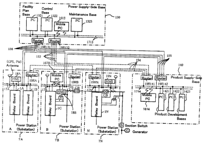
Numeral 130 designates a power supply-side base,
which is comprised of a network I/F 131, an electronic
terminal 132 such as personal computer and a RIO (remote
input output apparatus) 133. The power supply-side
base 130 mainly has a function of monitoring the power
system, and carries out monitoring of a system state
such as voltage, current, phase, failure point, failure
sort, failure content, load amount and the like in each
section of the power system.
Numeral 140 designates a product supply-side base
( for example, manufacturer side ) supplying to the power
21
CA 02374280 2002-03-04
supply side any product such as facility equipments
constituting the power system and an equipment control
apparatus. The product supply-side base 140 is
comprised of a network I/F 141, an electronic terminal
142 such as personal computer and a RIO ( remote input
output apparatus) 143, and mainly has a function of
maintaining and managing the equipment such as relay
function change and relay setting change. The product
supply-side 140, for example, carries out such
practical work, in terms of the maintenance and
management of the equipment constituting the power
system, as preservation, change, addition and partial
deletion of the power system function which directly
relates to system operation, e.g., packaging, change,
addition and partial deletion of relay setting
information, relay setting program, relay function
execution program and program for loading a relay
program and the like.
In addition to the mentioned power supply-side
base 130 having the function of the relay function
change and relay setting change, the product
supply-side base 140 also has a function of monitoring
the power system. Therefore, both of the mentioned
power supply-side base 130 and product supply-side base
140 serves not only as the monitoring control apparatus
but also as the power system management apparatus .
However, for reasons of better understanding, numeral
130 is hereinafter referred to as the power supply
side base, and numeral 140 is referred to as the product
supply-side base.
22
CA 02374280 2002-03-04
Numeral 151 designates a communication path for
carrying out exchange ( send and receive ) of information
between the mentioned common memory 113 in the
mentioned relay CPU 110 and the mentioned web sever 121
in mentioned Web CPU 120, which path is an internal bus
located in the mentioned relay board 1. Numeral 152
designates the communication path for carrying out the
exchange of information between the mentioned Web sever
121 and the mentioned network I/F 122, which path is
an internal bus located in the mentioned Web CPU 120.
Numeral 153 designates a communication path for
carrying out the exchange of information between the
network I/F 122 in the mentioned Web CPU 120 and the
network I/ F 131 in the mentioned power supply-side
base 130, and the path serves as a Web communication
net in the WWW (hereinafter referred to as "Web
communication net 153"). Numeral 154 designates a
communication path for carrying out the exchange of
information between the mentioned network I/F 122 and
the network I / F 141 in the mentioned product
supply-side base 140, which path is a Web communication
net in the WWW (hereinafter referred to as "Web
communication net 154" ) . In the foregoing description,
the network I / F 122 is connected to the Web
communication net 154. However, it is also preferable
that due to an intra-company communication
infrastructure, the Web communication net 153 is
connected via, e.g., a proxy server to the Internet,
and further connected via the Web communication net
within the manufacturer (equivalent to 154) to the
23
CA 02374280 2002-03-04
product supply-side base 140.
Numeral 155 designates a communication path for
carrying out the exchange of information between the
RIO 115 in the mentioned relay CPU 110 and the RIO 143
in the mentioned product supply-side base 140. The
communication path 155 is a dedicated communication
path independent of the mentioned Web communication
nets 153, 154, which path is to be referred to as
dedicated line or security line. Numeral 156
designates a communication path for carrying out the
exchange of information between the RIO 115 in the
mentioned relay CPU 110 and the RIO 133 in the mentioned
power supply-side base 130. The communication path
156 is an dedicated path independent of the mentioned
Web communication nets 153, 154, which path is to be
referred to as dedicated line or security line.
A relay program managing a relay function is
packaged into the mentioned relay CPU 110, and the
mentioned Web server 121 is packaged into the mentioned
web CPU 120. Further, the mentioned relay function is
roughly connected to the mentioned Web server 121 so
as to be capable of being operated only by the mentioned
relay CPU 110 irrespective of presence or absence of
the mentioned Web sever 121. All data or program
necessary for the operation of the mentioned relay
function is packaged into the internal memory 112 of
the mentioned relay CPU 110 . Trans fer of data between
the mentioned relay CPU 110 and the mentioned Web server
121 is conducted via a dedicated memory such as
mentioned common memory 113 so that the mentioned Web
24
CA 02374280 2002-03-04
server 121 may not be capable of directly accessing to
the data and program within the mentioned relay CPU 110.
It is preferable that information necessary for
monitoring the system state such as the voltage,
current, phase, failure point, failure sort, failure
content,' load amount and the like in each section of
the power system, is processed in the following manner .
That is, the information may be downloaded from the
mentioned internal memory 112 into the mentioned common
memory 113 to be stored in the common memory 113 by the
operation of the mentioned a processor 111, or may be
directly stored into the mentioned common memory 113
without downloadingfrom the mentioned internal memory
112. Furthermore, anyinformation orprogram exerting
a significant effect on the system operation such as
relay setting information, relay setting program,
relay function execution program (also referred to as
relay program) and program for loading the relay
program and the like, is not stored in the mentioned
common memory 113 but in the mentioned internal memory
112.
Next, with respect to delivery method of the
information regarding the monitoring system for
monitoring the system state such as voltage, current,
phase, failure point, failure sort, failure content,
load amount and the like, and transfer of the
information regarding the equipment maintenance
management control system for carrying out such
practical work in terms of maintenance and management
of the equipment constituting the power system as
CA 02374280 2002-03-04
preservation, change, addition, partial deletion and
the like of the power system function which directly
relates to the system operation including packaging,
change, addition, partial deletion and the like of the
relay setting information, relay setting program,
relay function execution program, program for loading
the relay program and the like, the following three
methods for applying the invention are now
illustratively described.
Method 1. (Web communication net-dependent
method)
First, transfer of the information about the
monitoring system carrying out the monitoring of the
system state, e.g., the foregoing voltage, current,
phase, failure point, failure content, load amount and
the like is carried out via the mentioned Web
communication nets 153, 154 between at least one of the
mentioned power supply-side base 130 and the mentioned
product supply-side base 140 and the mentioned common
memory 113. A state such as voltage, current, phase,
failure point, failure sort, failure content, load
mount and the like in each section of the power system
can be monitored on a display screen of at least one
of an electronic terminal 132 equipped with a display
function in the mentioned power supply-side base 130
and an electronic terminal 142 equipped with a display
function in the mentioned product supply-side base 140.
Subsequently, practical work in terms of
maintenance and management of the equipment
26
CA 02374280 2002-03-04
constituting the power system such as preservation,
change, addition, partial deletion and the like of the
power system function, which directly relates to the
system operation, including packaging, change,
addition, partial deletion and the like of the relay
setting information, relay setting program, relay
function execution program, program for loading the
relay program and the like, is conducted as follows.
First it is confirmed that the practical work is carried
out via the mentioned dedicated lines 155, 156 between
at least one of the power supply-side base 130 and the
mentioned product supply-side base 140 carrying out
this practical work and the mentioned relay CPU 110.
Then entry of the mentioned practical work is executed
from at least one of the electronic terminal 132
equipped with the display function in the mentioned
power supply-side base 130 and the electronic terminal
142 equipped with the display function in the mentioned
product supply-side base 140. This entry information
is first stored into the common memory 113 via the
mentioned Web communication nets 153, 154. When any
confirmation information about carrying out the
mentioned work has been previously entered, this entry
information is downloaded to the mentioned internal
memory 112, and the mentioned packaging, change,
addition, partial deletion and the like is executed.
Method 2. (Dedicated line-dependent method)
First, transfer of the information about the monitoring
system carrying out the monitoring of a system state
27
CA 02374280 2002-03-04
including the mentioned voltage, current, phase,
failure point, failure sort, failure content, load
amount and the like is conducted via the mentioned Web
communication nets 153, 154 between at least one of the
mentioned power supply-side base 130 and the mentioned
product supply-side bases 140 and the mentioned common
memory 113. A state of voltage, current, phase,
failure point, failure sort, failure content, load
amount and the like in each section of the power system
can be watched on the display screen of at least one
of the electronic terminal 132 equipped with the
display function in the mentioned power supply-side
base 130 and the electronic terminal 142 equipped with
the display function in the mentioned product
supply-side base 140.
Next, practical work in terms of maintenance and
management of the equipment constituting the power
system such as preservation, change, addition, partial
deletion and the like of the power system function which
directly relates to the system operation including
packaging, change, addition, partial deletion and the
like of the relay setting information, relay setting
program, relay function execution program, program for
loading the relay program is conducted in the following
manner. First it is confirmed that the practical work
is carried out between at least one of the power
supply-side base 130 and the mentioned product
supply-side base 140 carrying out this work and the
mentioned relay CPU 110 via the mentioned dedicated
lines 155, 156. Then, when carrying out the entry of
28
CA 02374280 2002-03-04
the mentioned practical work from at least one of the
electronic terminal 132 equipped with the display
function in the mentioned power supply-side base 130
and the electronic terminal 142 equipped with the
display function in the mentioned product supply-side
base 140, this entry information is stored via the
mentioned dedicated lines 155, 156 into the mentioned
internal memory 112. In this manner, the mentioned
packaging, change, addition, partial deletion and the
like is executed.
Method 3. (Method using both Web communication
net and dedicated line)
First, transfer of the information about the
monitoring system monitoring the system state
including the mentioned voltage, current, phase,
failure point, failure sort, failure content, load
amount and the like is carried out via the mentioned
Web communication nets 153, 154 between at least one
of the mentioned power supply-side base 130 and the
mentioned product supply-side base 140 and the
mentioned common memory 113. A state of voltage,
current, phase, failure point, failure sort, failure
content, load amount and the like in each section of
the power system can be monitored on the display screen
of at least one of the electronic terminal 132 equipped
with the display function in the mentioned power
supply-side base 130 and the electronic terminal 142
equipped with the display function in the mentioned
product supply-side base 140.
29
CA 02374280 2002-03-04
Next, It is confirmed that among the practical
works in terms of maintenance and management of the
equipment constituting the power system such as
preservation, change, addition, partial deletion and
the like of the power system function which directly
relates to the system operation including packaging,
change, partial deletion and the like of the relay
setting information, relay setting program, relay
function execution program, program for loading the
relay program and the like, any work which does not
exert an effect on the power system operation, for
example, a display layout on the display screen is
carried out in the following manner. The confirmation
of carrying out the practical work is made between at
least one of the power supply-side base 130 and the
mentioned product supply-side base 140 carrying out the
practical work via the mentioned dedicated lines 155,
156, and the mentioned relay CPU 110. When entry of
the mentioned practical work is carried out from at
least one of the electronic terminal 132 equipped with
the display function in the mentioned power supply-
side base 130 and the electronic terminal 142 equipped
with the display function in the mentioned product
supply-side base 140, this entry information is first
stored into the common memory 113 via the mentioned Web
communication nets 153, 154. When the confirmation
information about carrying out the mentioned work has
been previously entered, the entry information is
downloaded to the mentioned internal memory 112, and
then the mentioned packaging, change, addition,
CA 02374280 2002-03-04
partial deletion and the like are carried out.
Subsequently, it is confirmed that among the
practical works in terms of maintenance and management
of the equipment constituting the power system such as
preservation, change, addition, partial deletion and
the like of the power system function which directly
relates to the system operation including packaging,
change, addition, partial deletion and the like of the
relay setting information, relay setting program,
relay function execution program, program for loading
the relay program and the like, any work exerting an
effect on the power system operation, for example, a
work possible to cause a system failure or a work
possible to cause a drop of the system voltage is
carried out in the following manner. It is confirmed
that such a work is carried out between at least one
of the power supply-side base 130 and the mentioned
product supply-side base 140 carrying out the practical
work and the mentioned relay CPU 110 via the mentioned
dedicated lines 155, 156. Then, entry of the mentioned
practical work is carried out from at least one of the
electronic terminal 132 equipped with the display
function in the mentioned power supply-side base 130
and the electronic terminal 142 equipped with the
display function in the mentioned product supply-side
base 140. Thus, the entry information is stored via
the mentioned dedicated lines 155, 156 into the
mentioned internal memory 112 resulting in the
executionof thementioned packaging, change, addition,
partial deletion and the like.
31
CA 02374280 2002-03-04
In addition, relay operation, circuit breaker
trip and the like due to generation of any abnormal
state of the system such as ground fault or short
circuit is automatically carried out by the a processor
111 and the internal memory 112 located in the mentioned
relay CPU 110 being irrelevant to the foregoing methods
1 to 3. In the case of generation of any abnormal state
in the system such as ground fault or short circuit,
the execution of the foregoing methods 1 to 3 is stopped
or interrupted by the function of the a processor 111 .
Reporting of the generation of abnormal state such as
ground fault or short circuit as well as the mentioned
interruption is carried out by displaying the abnormal
state on the display screens of the related electronic
terminals 132, 142 and the display 116 of the relay,
or by announcing it.
The mentioned Web communication nets 153, 154
serving as communication system are general-purpose
communication nets. Therefore, it is certain that
capital investment cost, maintenance cost and the like
for the communication system becomes rather
inexpensive, but the Web communication nets can also
be accessed from any place other than the mentioned
power supply-side base 130 and the mentioned product
supply-side base 140. On the other hand, the mentioned
dedicated lines 155, 156 serving as communication
system are provided independentlyof the communication
system of the mentioned Web communication nets 153, 154
and arranged so as to carry out the transfer of
information via the mentioned individual RIOs 115, 133,
32
CA 02374280 2002-03-04
143. Therefore, the dedicated lines 155, 156 can be
accessed only from the mentioned power supply-side base
130 and the mentioned product supply-side base 140
thereby providing an extremely higher reliability in
view of security. Further, the communication system
is superior in strength and hardly breaks down
resulting in an extremely high reliability in terms of
soundness of the line.
From the technological viewpoint, what has been
described above can be summarized as follows:
1. The above-described power system management
method and system comprises: an equipment control
apparatus (a relay board, a substation control device,
a power generation control device and the like) 1 which
is provided on the side of facility equipments
constituting a power system and controls the mentioned
facility equipments; and a monitoring control
apparatus (electronic terminals 132, 142 and the like)
which is provided outside of the mentioned equipment
control apparatus 1 and obtains internal information
about the mentioned equipment control apparatus 1 via
Web communication nets 153, 154 for monitoring a state
of the mentioned power system from the mentioned
internal information; wherein the mentioned equipment
control apparatus 1 is changed in function from outside
of the mentioned equipment control apparatus 1 (a power
supply-side base 130, a product supply-side base 140
and the like) by means of a communication method of
higher security than the monitoring system via the
mentioned Web communication net. As a result of such
33
CA 02374280 2002-03-04
arrangement, from outside of the mentioned equipment
control apparatus l, the internal information
regarding the mentioned equipment control apparatus 1
can be obtained and the state of the mentioned power
system can be monitored with this internal information.
Further, function of the mentioned equipment control
apparatus 1 can be changed from outside of the mentioned
equipment control apparatus 1. Furthermore, it can be
prevented that any other person not in charge of
changing the function of the mentioned equipment
control apparatus 1 may unwillingly change the function
of mentioned equipment control apparatus 1.
2 . In the above-described power system management
method and system, in addition to the foregoing
paragraph 1, it is arranged such that a communication
of higher security than the monitoring system via the
mentioned Web communication nets 153, 154 can be
conducted using communication lines 155, 156 different
from the mentioned Web communication nets 153, 154 . As
a result, from outside of the mentioned equipment
control apparatus 1, the internal information
regarding the mentioned equipment control apparatus 1
can be obtained and the state of mentioned power system
can be monitored with this internal information.
Further, the function of the mentioned equipment
control apparatus 1 can be changed from outside of the
mentioned equipment control apparatus as a matter of
course. Furthermore, as compared with the case of
changing the function of the mentioned equipment
control apparatus 1 via the mentioned Web communication
34
CA 02374280 2002-03-04
nets 153, 154, it can be more securely prevented that
any other person not in charge of changing the function
of the mentioned equipment control apparatus 1 may
unwillingly change the function of the mentioned
equipment control apparatus 1.
3 . In the above-described power system management
method and system, in addition to the foregoing
paragraph 1, it is arranged such that after conducting
a confirmation communication via the mentioned
communication lines 155, 156, the function of the
mentioned equipment control apparatus 1 is changed via
the mentioned Web communication nets 153, 154 from
outside of the mentioned equipment control apparatus
1. As a result, from outside of the mentioned
equipment control apparatus 1, the internal
information regarding the mentioned equipment control
apparatus 1 can be obtained and the state of mentioned
power system can be monitored with this internal
information. Further the function of the mentioned
equipment control apparatus 1 can be changed from
outside of the mentioned equipment control apparatus
1 as a matter of course . Furthermore, as compared with
the case of changing the function of the mentioned
equipment control apparatus 1 simply via the mentioned
Web communication nets 153, 154, it can be more securely
prevented that any other person not in charge of
changing the function of the mentioned equipment
control apparatus 1 may unwillingly change the function
of the mentioned equipment control apparatus 1.
4 . In the above-described power system management
CA 02374280 2002-03-04
method and system, in addition to the foregoing
paragraph 1, it is arranged such that as to the function
of the equipment control apparatus 1 at least exerting
an effect on operation of the power system, the function
of the mentioned equipment control apparatus 1 is
changed from outside of the mentioned equipment control
apparatus 1 via the mentioned communication lines
155,156. As a result, from outside of the mentioned
equipment control apparatus 1, the internal
information regarding the mentioned equipment control
apparatus 1 can be obtained and the state of the
mentioned power system can be monitored. with this
internal information. Further the function of the
mentioned equipment control apparatus 1 can be changed
from outside of the mentioned equipment control
apparatus 1 as a matter of course. Furthermore, as
compared with the case of changing the function of the
mentioned equipment control apparatus 1 via the
mentioned Web communication nets 153, 154, as to the
function of the mentioned equipment control apparatus
1 at least exerting the effect on the operation of the
power system, it can be more securely prevented that
any other person not in charge of changing the function
of the mentioned equipment control apparatus 1 may
unwillingly change the function of the mentioned
equipment control apparatus 1.
5 . In the above-described power system management
method and system, in addition to the foregoing
paragraph 1, it is arranged such that the function of
the mentioned equipment control apparatus 1 is changed
36
CA 02374280 2002-03-04
from at least one of the product supply-side base 140,
which supplies at least one of the mentioned facility
equipments and the mentioned equipment control
apparatus l, and the power supply-side base 130. As
a result, from outside of the mentioned equipment
control apparatus l, the internal information
regarding the mentioned equipment control apparatus 1
can be obtained, and the state of mentioned power system
can be monitored with this internal information.
Further the function of the mentioned equipment control
apparatus 1 can be changed from at least one of the
mentioned product supply-side base 140 and the power
supply-side base 130. Furthermore it can be prevented
that any other person not in charge of changing the
function of the mentioned equipment control apparatus
1 may unwillingly change the function of the mentioned
equipment control apparatus 1.
6. In the above-described power system management
method and system, in addition to the foregoing
paragraph l, it is arranged such that the mentioned
equipment control apparatus 1 includes a CPU 110
managing the function thereof, the mentioned CPU 110
including an internal memory 112 and a common memory
113, mentioned internal memory 112 can be accessed via
mentioned dedicated lines 155, 156, and the mentioned
common memory 113 can be accessed via the mentioned Web
communication nets 153, 154. As a result, from outside
of the mentioned equipment control apparatus 1, the
internal information regarding the mentioned
equipment control apparatus 1 can be obtained, and the
37
CA 02374280 2002-03-04
state of the mentioned power system can be monitored
with this internal information. Furthermore, the
function of the mentioned equipment control apparatus
1 can be changed from at least one of the mentioned
product supply-side base 140 and power supply-side base
130. Further it can be prevented that any other person
not in charge of changing the function of the mentioned
equipment control apparatus 1 may unwillingly change
the function of the mentioned equipment control
apparatus 1 via the mentioned Web communication nets
153, 154
7 . In the above-described power system management
system, it is arranged such that the common memory 113
is used only for reading with respect to the access via
the mentioned Web communication nets 153, 154. As a
result, the mentioned common memory 113 cannot be
rewritten so as to change the function of the mentioned
equipment control apparatus 1 by the access via the
mentioned Web communication nets 153, 154. Therefore
it can be more securely prevented that any other person
not in charge of changing the function of the mentioned
equipment control apparatus may unwillingly change the
function of the mentioned equipment control apparatus
1 via the mentioned Web communication net.
Embodiment 2.
Now, a second embodiment is hereinafter described
with reference to Fig. 2. In the drawing, reference
numerals 1551, 1552 designate dedicated lines between
the RIO 143 in the mentioned product supply-side base
38
CA 02374280 2002-03-04
140 and the RIO 115 in the mentioned relay CPU 110.
Reference numerals 1561, 1562 designate dedicated
lines between the RIO 133 in mentioned power
supply-side base 130 and the RIO 115 in the mentioned
relay CPU 110.
In the case that a request for access has been
made from the mentioned product supply-side base 140
to the mentioned relay CPU 110 via the mentioned
dedicated line 1551, whether or not such a request for
access has been made from the mentioned product
supply-side base 140 is confirmed by the mentioned
relay CPU 110 side via the mentioned dedicated line 1552 .
Only after having confirmed that the access request was
made from the mentioned product supply-side base 140,
the access is permitted to the mentioned product
supply-side base 140 via the mentioned dedicated line
1552. The mentioned product supply-side base 140
starts the access after receiving the mentioned
permission.
In the same manner, in the case that a request
for access to the mentioned relay CPU 110 has been made
from the mentioned power supply-side base 130 via the
mentioned dedicated line 1561, whether or not such a
request for access has been made from the mentioned
power supply-side base 130 is confirmed by the
mentioned relay CPU 110 side via the mentioned
dedicated line 1562. Only after having confirmed that
the access request was made from the mentioned power
supply-side base 130, the access is permitted to the
mentioned power supply-side base 130 via the mentioned
39
CA 02374280 2002-03-04
dedicated line 1562. The mentioned power supply-side
base 130 starts the mentioned access after receiving
the mentioned permission.
The remaining arrangement of this second
embodiment is the same as the foregoing first
embodiment (Fig. 1) and therefore further description
thereof is omitted herein. In the same manner,
transfer method of information regarding the
monitoring system for monitoring the system state such
as voltage, current, phase, failure point, failure sort,
failure content, load amount and the like, and transfer
method of information regarding the equipment
maintenance management control system for carrying out
such practical works in terms of the maintenance and
management of the equipment constituting the power
system as preservation, change, addition, partial
deletion and the like of the power system function which
directly relates to the system operation including
packaging, change, addition, partial deletion and the
like of the relay.setting information, relay setting
program, relay function execution program, program for
loading the relay program and the like, are also the
same as the methods 1 to 3 according to the foregoing
first embodiment (Fig. 1), except what is described
above being peculiar to this second embodiment, and
further description thereof is omitted herein.
In this second embodiment, as described above,
there is a protocol in which any access request to the
mentioned relay CPU 110 and permission to the access
are preliminarily confirmed before starting the access.
CA 02374280 2002-03-04
Therefore, reliability in security becomes higher than
that in the case according to the foregoing first
embodiment . In addition, in the case that only a read
request is made to the mentioned relay CPU, it is
preferable that the access to the mentioned relay CPU
110 is permitted without execution of the confirmation
via the mentioned dedicated lines 1552, 1562.
Embodiment 3.
Now, a third preferred embodiment is hereinafter
described with reference to Fig. 3. In the drawing,
reference numeral 157 designates a dedicated signal
line channel, and a switch 158 which is artificially
ON / OFF controlled is inserted therein. Only in the
case of this switch 158 being ON, the mentioned
dedicated line 155 is operative, and the RIO 115 on the
side of mentioned relay board 1 operates such that
transfer of information may be carried out between the
electronic terminal 142 in the mentioned product
supply-side base 140 and the ,u processor 111 in the
mentioned relay CPU 110. In the same manner, only in
the case of the mentioned switch 158 being ON, the
mentioned dedicated line 156 is operative, and the RIO
115 on the side of mentioned relay board 1 operates such
that transfer of information may be carried out between
the electronic terminal 132 of the mentioned power
supply-side base 130 and the mentioned ~ processor
111.
Further, the mentioned switch 158 is controlled
to turn ON by an agreement reached between the mentioned
41
CA 02374280 2002-03-04
power supply-side base 130 and an electric power
station side provided with the relay board 1, an
agreement reached between the mentioned product
supply-side base 140 and the electric power station
side provided with the mentioned relay board 1, an
agreement reached between mentioned power supply-side
base 130, mentioned power supply-side base 140 and the
electric power station provided with mentioned relay
board~l, and the like.
Furthermore, in the case that a request made
toward the mentioned relay CPU 111 via the mentioned
dedicated lines 155, 156 is a writing request, it is
preferable that access to the mentioned relay CPU 110
can be carried out only during the ON state of the
mentioned switch 158. It is also preferable that in
the case of the request made toward the mentioned relay
CPU 110 is only a read request, the access toward the
mentioned relay CPU 110 can be carried out irrespective
of the ON / OFF state of the mentioned switch 158.
The remaining arrangement of this third
embodiment is the same as the foregoing first
embodiment (Fig. 1) and therefore further description
thereof is omitted herein. In the same manner,
transfer method of information regarding the
monitoring system for monitoring the system state such
as voltage, current, phase, failure point, failure sort,
failure content, load amount and the like, and transfer
method of information regarding the equipment
maintenance management control systemfor carrying out
such practical works in terms of the maintenance and
42
CA 02374280 2002-03-04
management of the equipment constituting the power
system as preservation, change, addition, partial
deletion and the like of the power system function which
directly relates to the system operation including
packaging, change, addition, partial deletion and the
like of the relay setting information, relay setting
program, relayfunction execution program, programfor
loading the relay program and the like, are also the
same as the methods 1 to 3 according to the foregoing
first embodiment (Fig. 1), except what is described
above being peculiar to this third embodiment, and
further description thereof is omitted herein.
As described above, in the power system
management system according to this third embodiment,
the mentioned communication lines 155, 156 are arranged
so as to provide a connection between at least one of
the electronic terminals 142, 132 respectively of the
product supply-side base 140 and the power supply-side
base 130 and the mentioned equipment control apparatus
(relay board) 1, depending on the switch 158
artificially ON / OFF controlled. Therefore, in
addition to the function according to the foregoing
first embodiment, at least one of the electronic
terminals 132, 142 of the power supply-side base 130
and the mentioned product supply-side base 140 and the
mentioned equipment control apparatus 1 are connected
to each other, depending on the switch 158 artificially
ON / OFF controlled. As a result, it can be further
securely prevented that any other person not in charge
of changing the function of the mentioned equipment
43
CA 02374280 2002-03-04
control apparatus 1 may unwillingly change the function
of the mentioned equipment control apparatus 1.
Embodiment 4.
Now, a fourth embodiment is hereinafter described
with reference to Fig. 4. In the drawing, reference
numeral 134 designates a switch which is provided in
the mentioned power supply-side base 130 and
artificially ON / OFF controlled. Numeral 144
designates a switch which is provided in the mentioned
product supply-side base 140 and artificially ON/OFF
controlled. Eitherof thementionedswitches 134, 144,
as shown in the drawing, is in parallel to the switch
158 which is provided on the side of the mentioned relay
board 1 and artificially ON / OFF controlled.
Furthermore, it is arranged such that depending
on one of these switches 134, 144, 158, at least one
of the electronic terminals 132, 142 respectively of
the mentioned power supply-side base 130 and product
supply-side base 140, and the mentioned equipment
control apparatus (relay board and the like) 1 are
connected to each other. In either of at least one of
the mentioned power supply-side base 130 and product
supply-side base 140 and the mentioned equipment
control apparatus 1 side, a person in charge of changing
the function of the mentioned equipment control
apparatus 1 can change the function of the mentioned
equipment control apparatus 1. In addition, it can be
securely prevented that any other person not in charge
of changing the function of the mentioned equipment
44
CA 02374280 2002-03-04
control apparatus I may unwillingly change the function
of the mentioned equipment control apparatus 1.
The remaining arrangement of this fourth
embodiment is the same as the foregoing first
embodiment (Fig. 1) and therefore further description
thereof is omitted herein. In the same manner,
transfer method of information regarding the
monitoring system for monitoring the system state such
as voltage, current, phase, failure point, failure sort,
failure content, load amount and the like, and transfer
method of information regarding the equipment
maintenance management control systemfor carrying out
such practical works in terms of the maintenance and
management of the equipment constituting the power
system as preservation, change, addition, partial
deletion and the like of the power system function which
directly relates to the system operation including
packaging, change, addition, partial deletion and the
like of the relay setting information, relay setting
program, relay function execution program, program for
loading the relay program and the like, are also the
same as the methods 1 to 3 according to the foregoing
first embodiment (Fig. 1), except what is described
above being peculiar to this fourth embodiment, and
further description thereof is omitted herein.
Embodiment 5.
Now, a fifth embodiment is hereinafter described
with reference to Fig. 5. As shown in Fig. 5, the switch
134 which is provided in the mentioned power
CA 02374280 2002-03-04
supply-side base 130 and artificially ON / OFF
controlled, is connected in series to the switch 158
which is provided on the side of the mentioned relay
board 1 and artificially ON/OFF controlled. Also the
switch 144 which is provided in the mentioned product
supply-side base 140 and artificially ON / OFF
controlled, is connected in series to mentioned switch
158 provided on the side of the mentioned relay board
1. Further, the switch 134 in the mentioned power
supply-side base 130 and the switch 144 in the mentioned
product supply-side base 140 are in parallel to each
other.
In this fifth embodiment, the switch artificially
ON/OFF controlled is provided respectively in each of
the mentioned power supply-side base 130 and product
supply-side base 140 and on the side of mentioned
equipment control apparatus 1 (134, 144, 158).
Depending on both of one of the switches 134, 144 of
the mentioned respective bases 130, 140 and the switch
158 on the side of the mentioned equipment control
apparatus 1, one of the electronic terminals 132, 142
in the mentioned respective bases 130, 140 and the
mentioned equipment control apparatus 1 are connected
to each other via the communication lines 155, 156.
Thus, it is not until reaching an agreement between
either of the mentioned respective bases 130, 140 and
the side of the mentioned equipment control apparatus
1 that the function of the mentioned equipment control
apparatus 1 can be changed. Therefore, it can be
further securely prevented that any other person not
46
CA 02374280 2002-03-04
in charge of changing the function of the mentioned
equipment control apparatus 1 may unwillingly change
the function of the mentioned equipment control
apparatus 1.
The remaining arrangement of this fifth
embodiment is the same as the foregoing first
embodiment (Fig, 1) and therefore further description
thereof is omitted herein. In the same manner,
transfer method of information regarding the
monitoring system for monitoring the system state such
as voltage, current, phase, failure point, failure sort,
failure content, load amount and the like, and transfer
method of information regarding the equipment
maintenance management control systemfor carrying out
such practical works in terms of the maintenance and
management of the equipment constituting the power
system as preservation, change, addition, partial
deletion and the like of the power system function which
directly relates to the system operation including
packaging, change, addition, partial deletion and the
like of the relay setting information, relay setting
program, relayfunction execution program, program for
loading the relay program and the like, are also the
same as the methods 1 to 3 according to the foregoing
first embodiment (Fig. 1), except what is described
above being peculiar to this fifth embodiment, and
further description thereof is omitted herein.
Embodiment 6.
In a sixth embodiment, as shown in Fig. 6, the
47
CA 02374280 2002-03-04
switch 134 which is provided in the mentioned power
supply-side base 130 and artificially ON / OFF
controlled, the switch 144 which is provided in the
mentioned product supply-side base 140 and
artificially ON / OFF controlled, and the switch 158
which is provided on the side of mentioned relay board
1 and artificially ON / OFF controlled, are all
connected in series to one another.
In this sixth embodiment, the mentioned switches
artificially ON/OFF controlled are provided in each
of the mentioned power supply-side base 130 and product
supply-side base 140, and on the side of the mentioned
equipment control apparatus (relay board and the like)
1. Depending on all of the switches 134, 144 of the
mentioned respective bases 130, 140 and the switch 158
on the side of the mentioned equipment control
apparatus 1, at least one of the electronic terminals
132, 142 of the mentioned respective bases 130, 140 and
the mentioned equipment control apparatus 1 are
connected to each other via the communication lines 155,
156. Thus, it is not until reaching an agreement among
the three of the mentioned power supply-side base 130,
the mentioned product supply-side base 140 and the side
of the mentioned equipment control apparatus 1 that the
function of the mentioned equipment control apparatus
1 can be changed. Therefore, it can be securely
prevented without fail that any other person not in
charge of changing the function of the mentioned
equipment control apparatus 1 may unwillingly change
the function of the mentioned equipment control
48
CA 02374280 2002-03-04
apparatus 1.
The remaining arrangement of this sixth
embodiment is the same as the foregoing first
embodiment (Fig. 1) and therefore further description
thereof is omitted herein. In the same manner,
transfer method of. information regarding the
monitoring system for monitoring the system state such
as voltage, current, phase, failure point, failure sort,
failure content, load amount and the like, and transfer
method of information regarding the equipment
maintenance management control systemfor carrying out
such practical works in terms of the maintenance and
management of the equipment constituting the power
system as preservation, change, addition, partial
deletion and the like of the power system function which
directly relates to the system operation including
packaging, change, addition, partial deletion and the
like of the relay setting information, relay setting
program, relay function execution program, program for
loading the relay program and the like, are also the
same as the methods 1 to 3 according to the foregoing
first embodiment (Fig. 1), except what is described
above being peculiar to this sixth embodiment, and
further description thereof is omitted herein.
Embodiment 7.
Now, a seventh embodiment is described with
reference to Fig. 7 showing an arrangement in which the
internal memory 112 and the common memory 113 in the
relay CPU 110 are mounted on the same chip. In the
49
CA 02374280 2002-03-04
drawing, the mentioned internal memory 112 includes a
memory body 1121 and an I/F 1122, and the mentioned
common memory 113 includes a memory body 1131 and an
I/ F 1132. That is, although the mentioned internal
memory 112 and common memory 113 are mounted on the same
chip, they include separately the memory body and I
/ F. Accordingly, from the Web server 121 of the
mentioned Web CPU 120, access is possible only to the
memory body 1131 of the common memory 113 via the I
/ F 1132 of the common memory 113 . In other words, the
Web sever 121 of the mentioned Web CPU 120 is connected
via a connector (not shown) to the I/ F 1132 of the
mentioned common memory 113, while being not connected
to the I/F 1122 of the mentioned internal memory 112.
The mentioned internal memory 112 and common
memory 113 are formed into different chips in the
foregoing Embodiments 1 to 6, while they are formed into
the same chip in this embodiment 7. what is important
is that the internal memory 112 and the Web server 121
are not connected to each other in terms of the
communication path (physically separated on the
communication path). This makes it impossible to
access from the mentioned Web sever 121 to the internal
memory 112 in which any program or processing data of
the equipment control apparatus such as relay program
or live data about the system state are stored.
However, in the case of carrying out any access to the
common memory 113 from the Web server 121 and any
download to the common memory 113 from the internal
memory 112 at the same time, there is a possibility that
CA 02374280 2002-03-04
the physical separation on the communication path
between the internal memory 112 and the Web sever 121
becomes weak. Supposing that security measures on the
S/ W are employed together, the reliability will be
further improved.
The remaining arrangement of this seventh
embodiment is the same as the foregoing first
embodiment (Fig. 1) and therefore further description
thereof is omitted herein. In the same manner,
transfer method of information regarding the
monitoring system for monitoring the system state such
as voltage, current, phase, failure point, failure sort,
failure content, load amount and the like, and transfer
method of information regarding the equipment
maintenance management control system for carrying out
such practical works in terms of the maintenance and
management of the equipment constituting the power
system as preservation, change, addition, partial
deletion and the like of the power system function which
directly relates to the system operation including
packaging, change, addition, partial deletion and the
like of the relay setting information, relay setting
program, relayfunction execution program, program for
loading the relay program and the like, are also the
same as the methods 1 to 3 according to the foregoing
first embodiment (Fig. 1), except what is described
above being peculiar to this seventh embodiment, and
further description thereof is omitted herein.
Embodiment 8.
51
CA 02374280 2002-03-04
Next, an eighth embodiment is hereinafter
described with reference to Fig. 8. Fig. 8 shows a
specific example in the case of applying the invention
to a protection control system of a power system. In
the drawing, reference numerals 7A to 7N designate A,
B, C power stations (substations). As shown in the
drawing, provided in the station are a transformer (not
shown), relay boards (protection relay apparatus) 1A
to 1N provided with a protection control function, an
a circuit breaker CB, an instrument current transformer
CT, an instrument transformer PT, etc. When detecting
any fault on a transmission line or a bus, the mentioned
relay boards (protection relay apparatus ) 1A to 1N trip
the circuit breaker CB and at the same time collect
information regarding the system state (for example,
information showing the ON/ OFF state of the circuit
breaker CB and a section switch S mounted on the bus,
information regarding bus voltage, bus current and
zero-phase current, and so on) . Then, the relay boards
store those collected information as live data
information concerning the system state in the internal
memory ( the internal memory 112 in Figs . 1 to 7 ) of the
mentioned relay boards (protection relay apparatus) 1A
to 1N.
Reference numeral 130 designates a power
supply-side base such as central power feeding station,
control station, branch, etc . in which a facility plan
base, a control base, a maintenance base and the like
are provided. Reference numeral 140 designates a
product supply-side base where any product such as
52
CA 02374280 2002-03-04
facility equipments constituting the power system and
the control apparatus controlling the mentioned
facility equipments is developed, manufactured or
marketed. A plurality of product development bases is
arranged in this product supply-side base 140.
Further, at the mentioned power supply-side base 130,
apparatus provision-side base 140, power station
(substation) 7B, etc., mobile PCs 167B, 1613, 1614
having substantially the same function as the mentioned
electronic terminals 132, 142 are also used.
Numerals 1321 to 1323 designate PCs with display
(electronic terminal) such as personal computer that
is used at the mentioned power supply-side base 130.
Numerals 1421 to 1423 designate PCs with the display
(electronic terminal) such as personal computer used
at the mentioned product supply-side base 140. A Web
browser (not shown) is mounted on each of these PCs
(electronic terminals) 1321 to 1323, 1421 to 1423.
This Web browser establishes a connection via the Web
communication nets 153, 154 to the Web server mounted
on the mentioned relay boards 1A to 1N (Web server 121
in Figs. 1 to 7). Numeral 17A designates a
communication line in the mentioned A power station
(substation) 7A. Numeral 17B designates a
communication line in the mentioned B power station
(substation) 7B. Numeral 17N designates a
communication line in the mentioned N power station
(substation) 7N. Numeral 1713 designates a
communication line in the mentioned power supply-side
base 130. Numeral 1714 designates a communication
53
CA 02374280 2002-03-04
line in the mentioned product provision-side base 140.
Numeral 18A designates a Human Machine Interface
(hereinafter referred to as HMI) provided in the
mentioned A power station (substation) 7A. Numeral
18B designates a HMI provided in the mentioned B power
station (substation) 7B. Numeral 18N designates a HMI
provided in the mentioned N power station (substation)
7N. Numeralsl9RA, 198B, 198N, 198131, 198132, 198133,
198141, 198142 designate routers. In addition, the
Web communication net and the communication line
connected to the Web communication net in the station
are indicated by dotted lines, while the dedicated line
and the communication line connected to the dedicated
line in the station being indicated by solid lines.
Now the operation is hereinafter described.
The mentioned relay boards 1A to 1N are mounted
with the I/F (interface) capable of collecting system
state information , for example, information showing
an ON/OFF state of the circuit breaker CB mounted on
the bus, and stores the system state information in the
internal memory (the internal memory 112 in Figs . 1 to
7) of the relay boards as live data information
concerning the system state.
On the other hand, the mentioned PC 1323 for
maintenance provided at the mentioned maintenance base
in the mentioned power supply-side base 130 such as
power sales company carries out maintenance as follows.
For example, in the case of judging on the PC display
screen whether or not any transmission line connected
to the mentioned A electric power station is in a normal
54
CA 02374280 2002-03-04
condition, the PC 1323, using the mentioned Web browser
(not shown) , outputs to the mentioned Web communication
net 153 an address information that identifies only the
mentioned relay board 1A in the mentioned A electric
power station, thereby trying to achieve a connection
to the Web server ( the Web server 121 in Figs . 1 to 7 )
mounted on the mentioned relay board 1A. When the
mentioned Web server mounted on the mentioned relay
board 1A receives the address information, a connection
between this Web server and the Web browser of the
mentioned PC 1323 is established.
In this manner, when the connection between
mentioned Web browser and the Web server in the
mentioned relay board 1A is established, a HTTP
communication between the mentioned Web browser and the
Web server in the mentioned relay board 1A comes to
start. The mentioned PC 1323 for maintenance, using
the Web browser, outputs a transmission request for the
system state information to the Web server of the
mentioned relay board 1A. When receiving the
transmission request for the system state information
from the mentioned PC 1323 for maintenance via the Web
communication net 153, the Web server mounted on the
mentioned relay board 1A transfers the system state
information, which is downloaded from the internal
memory in the mentioned relay board 1A (the internal
memory 112 in Figs . 1 to 7 ) to the common memory ( the
common memory 113 in Figs . 1 to 7 ) , via the mentioned
Web communication net 153 to the mentioned PC 1323 for
maintenance.
CA 02374280 2002-03-04
Accordingly, the mentioned PC 1323 for
maintenance can judge on the PC display screen whether
or not the transmission line connected to the mentioned
A power station 7A is in a normal state . In addition,
by mounting a Java VM on the mentioned PC 1323 for
maintenance, the program or the like for displaying the
system state information on the display screen is
downloaded via the Web communication net 153 from the
mentioned common memory in the mentioned relay board
1A ( the common memory 113 in Figs . 1 to 7 ) upon execution
of the Java. Therefore, it is not necessary for
previously installing such a program into the PC 1323.
Described above is the operation in which the
system state information downloaded to the common
memory in the mentioned relay boards 1A to 1N is
obtained using the mentioned Web browser by means of
the PC 1323 for maintenance. However, change in the
operation setting information of the protection relay
apparatus which information is stored in the internal
memory in the mentioned relay boards 1A to 1N is carried
out via the dedicated line 156. The other PCs
(electronic terminals) 1321, 1322, 1421, 1422, 1423
except the mentioned PC 1323 for maintenance also have
the same function as the foregoing PC 1323 for
maintenance.
In addition, right of making a reference to the
electronic data is managed by means of an IP of the
Internet in order to prevent the information from being
flowed out to any person other than those previously
permitted. The mentioned electronic data are
56
CA 02374280 2002-03-04
concealed by means of encryption (encoding) of the
Internet in order to prevent the electronic data being
tapped on the mentioned Web communication nets 153,
154.
57