Note: Descriptions are shown in the official language in which they were submitted.
CA 02374625 2001-11-19
WO 01/70078 PCT/USO1/08224
-1-
CONSTANT RESTORING FORCE SUPPORT SURFACE
Technical Field
This invention relates to an all mechanical support surface which
synthesizes the flotation properties of a true fluid. Specifically, this
invention
S relates to a non-pneumatic support surface that has the capability of
assuming
the shape of the person lying or sitting on it to minimize the force
differential on
different area~:yo~ 'the. shin. of .such person. This characteristic of the
support
suiface~'ts .particularly critical to facilitate blood flow particularly where
the user
is handicapped, bedridden or 'disabled.
Background Art
The present invention provides the flotation properties of a true fluid as
follows: ( 1 ) Low surface tension caused by providing a highly displaceable
s~apport_~urface. (2) Buoyancy caused by providing suspension forces that have
a-constant restoring force which is independent of immersion depth. (3) Wetted
1 S surface equivalence is provided by shape compliance, where the application
of
suspension forces at the tissue-surface interface has multiple degrees of
freedom
to align with and envelope the shape of the person at the contacted surface
areas. (4) Low friction to maintain the constant restoring force properties of
the
moving elements (piston) throughout the immersion depth of the device. (5)
Low friction at the tissue interface, using dry lubricant techniques, e.g.,
teflon-
coated fabrics, to permit some sliding as the shape fitting is occurring. (6)
Viscosity control with dash-pot techniques, to maintain the feel of a true
fluid
and to provide slow changes when a floating body moves. Motion control is of
great importance when serving the safety needs of the disabled person. High
viscosity, however, does not provide positional stability to the supported
object.
Stability is defined as: when an object moves after receiving a disturbing
force
it will return to its initial position after the disturbing force is removed.
A support surface having the foregoing characteristics is especially
important when used by persons prone to decubitus ulcers which occur when
deformation occurs on areas of the body inducing interference with the flow of
blood at the contacted site.
CA 02374625 2001-11-19
WO 01/70078 PCT/USO1/08224
-2-
One solution to this problem is the use of cellular air filled cushions and
the inventor of this application has numerous patents which are directed to
air
inflatable cushions which have upstanding soft flexible cells, many of which
have finned sides, known as ROHO DRY FLOTATION cushions and
mattresses. Among these are patent numbers 3605145, 3870450, 4005236, and
4541136, all issued to Robert H. C'rraebe. These cushions are made from
neoprene rubber or plastic films to create a highly displaceable high
resolution
surface. The cells also are interconnected pneumatically in what are known as
"feedback pathways." The cells in a particular cushion may all be
interconnected or sets of said cells can be isolated from other sets in the
same
cushion with the cells in each set interconnected to allow for positioning of
the
user in a desired stable position on the cushion. Among patents with such
configurations are 5052068, 5163196, and 5461741. These cellular air-filled
cushions can be constructed to fit on the mechanical piston of this invention.
In the ROHO cushions, each air cell acts as a piston to develop constant
restoring forces as a function of its internal air pressure and because of the
feedback pathways they all have the same restoring force to buoy up the person
being supported. The use of feedback pathways causes a catastrophic failure
mode, when an aircell develops a leak, and the support surface goes flat. By
design each air cell has the same effective piston size to assure uniformity
of
forces across the support surface. Having different sized pistons and
therefore
non-uniform forces produces a change in wetted surface area and shape
compliance but the total summation of all the suspension forces contributing
to
buoyancy still must equal the weight of the person being supported. Uniform
cell (piston) size and/or cell shape facilitates production and inventory
issues
more than suspension performance results. These air filled cushions or
mattresses with slow air flow feedback paths create a high viscosity effect
and
permit selecting immersion depth for each individual by adjusting the internal
working pressure of the cushion.
The soft flexible cells provide multiple (6) degrees of freedom at the
tissue interface by deforming to align with the contours of the supported
object
to enhance its wetting equivalence to a true fluid. The multiple fin design is
CA 02374625 2001-11-19
WO 01/70078 PCT/USO1/08224
-3-
employed to create gluing surfaces between individual cells and may have some
effect on suspension performance which cannot be measured when compared to
a more simple non-finned cell.
It is a principal object of the present invention is to provide a mechanical
device which emulates the effect of the aforementioned ROHO air cell cushions
and mattresses. Another object is to provide a cushion and mattress
constructed
from rigid materials which still will provide the flotation properties of a
true
fluid. Still another object is to provide a cushion and mattress which has a
series of reciprocal piston heads which are controlled by constant restoring
force springs whereby the force exerted by the piston head is constant
regardless
of its travel within its movement limits.
A further object of this invention is to provide a cellular cushion and
mattress construction in which the cells (pistons) are mechanical and are
easily
replaceable to adjust the restoring force of the cells to accommodate users of
various body weights and contact areas. A further object is to provide a means
to dampen piston movement rates to create viscosity control. A further object
is
to provide a support surface that does not have a catastrophic failure mode.
Still another object is to provide a mechanical cushioned mattress using
reciprocal piston rods operated by constant restoring force springs which can
be
located inside or outside the piston to change the surface area and density of
the
pistons. Another object is to provide mechanical piston operated cushions and
mattress in which the end of the piston rod has multiple degrees of freedom.
These and other objects and advantages will become apparent hereinafter.
Summary of the Invention
The present invention comprises mechanically operated mattresses and
cushions which are controlled by constant restoring force springs and the
arrangements and combination of parts simulate the flotation properties of a
true
fluid.
Brief Description of Drawings
In the accompanying drawings which form part of the specification and
wherein like numerals and letters refer to like parts wherever they occur;
CA 02374625 2001-11-19
WO 01/70078 PCT/USO1/08224
-4-
Figure 1 is a side elevational view of a single constant restoring force
piston;
Fig. 1A is a fragmentary sectional view taken along line lA-lA of Fig.
1;
Fig. 1 B is a fragmentary sectional view taken along line 1 B-1 B of Fig.
1;
Fig. 1 C is a view similar to Fig. 1 B, but showing an air cell cushion
topping the piston head;
Fig. 1 D is a view similar to Fig. 1 B but showing a spring between the
piston head and the cap;
Fig. 1 E is a view similar to Fig. 1 B but showing a ball and socket
connection between the piston head and cap;
Figure 2 is a sectional view taken along line 2-2 of Fig. 1;
Figure 3 is a sectional view taken along line 3-3 of Fig. 1;
Figure 4 is a sectional view taken along line 4-4 of Fig. 1;
Figure 5 is a top plan view of an array of pistons formed into a support
surface;
Fig. 5A is a fragmentary plan view of a portion of the top member of the
support surface of Fig. 5; '
Fig. 6 is a vertical sectional view taken along line 6-6 of Fig. S;
Fig. 6A is an end elevational view of a modification of the invention;
Fig. 6B is an end elevational view of another modification of the
invention;
Fig. 6C is a top plan view of another modification of the invention;
Fig. 7 is an end elevational view of another modification of the
invention;
Fig. 8 is a vertical sectional view taken along line 8-8 of Fig. 7;
Fig. 8A is a fragmentary vertical sectional view of a modification of the
invention;
~0 Fig. 9 is a vertical sectional view of another modification of the
mvenhon;
CA 02374625 2001-11-19
WO 01/70078 PCT/USO1/08224
-5-
Fig. 9A is a vertical sectional view of another modification of the
invention;
Fig. 10 is a fragmentary sectional view taken along line 10-10 of Fig.
9A;
Fig. 10A is a fragmentary view partly in section showing a modification
of the invention;
Fig. 11 is a fragmentary diagrammatic side view showing a person
sitting on a cushion of this invention;
Fig. l 1A is a view similar to Fig. 11 taken along line 11A-11A of Fig.
11;
Fig. 11B is a view similar to Fig. 11 taken along line 11B-11B of Fig.
11; and
Fig. 12 is a fragmentary diagrammatic side view showing a person lying
on a mattress of this invention.
The invention also consists in the parts and in the arrangements and
combinations of parts hereinafter described and claimed.
Best Mode for Carr~n~ Out the Invention
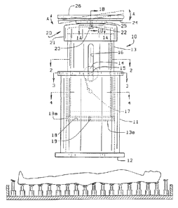
Figs. 1-4 show a constant restoring force member or piston 10 which
comprises a second tubular member 11 positioned on a base 12 and a first
tubular member 13 slidable in and guided by the second tubular member 11. A
constant restoring force return spring 14 interconnects the members 11 and 13.
The spring 14 is mounted on a rod 15 which is anchored to the second tubular
member 11 and slides through longitudinal slots 16 in the first tubular member
13. One end of the spring 14 is anchored to a rod 17 positioned in the first
tubular member 13. The constant restoring force spring 14 can be any
commercially available spring such as the SPEC ~ BRAND spring sold by
ASSOCIATED SPRING RAYMOND BARNES GROUP of Cory,
Pennsylvania 16407. The characteristic of the spring 14 is that its rating
determines the force necessary for relative movement between the cylinders 11
and 13 and the restoring force on the first member 13 is constant within its
limits of travel regardless of the depth of its immersion in the second member
11.
CA 02374625 2001-11-19
WO 01/70078 PCT/USO1/08224
-6-
The constant restoring force spring 14 is located inside the first member
13 to provide a force component that is acting along the centerline of the
member 13 to minimize side loading which can cause friction between the
member 13 and the member 11.
A preferred embodiment of the invention includes a bottom member 13a
on the first tubular member 13. The bottom member 13a has a groove 18 in
which is positioned an O-ring seal 18a. The seal 18a engages the inside wall
11 a of the second tubular member 11 and tends to prevent escape of air past
it
as the first tubular member 13 moves into the second tubular member 11. An
opening 19 is located through the bottom member 13a to provide controlled
escape of air past the bottom member 13a as the first member 13 moves into the
second member 11. This provides a damper on the rate of movement of the first
member 13 and creates an effect similar to a controlled viscosity fluid. This
provides a smooth controlled feel for the person sitting on the piston
assembly.
Positioned on the free or outer end of the first cylinder 13 is a top
structure 20 which includes a base cap 21 which can be frictionally mounted on
the end of the first cylinder 13. The cap 21 has a central aperture 22 in
which a
rivet 23 (or a ball and socket joint) is loosely positioned. The rivet 23 is
slidable and tiltable in the aperture 22. The outer end of the rivet 23 is
fixed to
a rigid disc 24. Thus, the disc 24 is tiltable with respect to'the cap 21. A
resilient compressible buffer 25 is positioned around the rivet 23 between the
cap 21 and the bottom side of the disc 24, to act as a spring to align an
unloaded
disk. The combination of the rivet 23, the enlarged cap opening 22, and the
resilient washer 25 allows the disc 24 to have a universal type movement with
multiple degrees of freedom with respect to the tubular member 13 (indicated
by the arrows A in Fig. 1 ).
As noted an alternative construction (useful in production embodiments)
is a ball and socket arrangement. This is shown in Fig. 1E. The ball 35 is
attached to a stem 36 which is fixed to the disc 24. A socket 37 is formed in
the
cap 21 to allow movement of the disc 24 with respect to the cap 21.
To enhance a soft surface feel, a foam top member 26 may be positioned
on the outer surface of the disc 24.
CA 02374625 2001-11-19
WO 01/70078 PCT/USO1/08224
_7_
If desired, a sealed cell or interconnected cell air-filled cushion 27 (Fig.
1 C) can be positioned on top of the foam paid 26. The air-filled cellular
cushion 27 also can be attached directly to the rigid disc 24 omitting the
foam
pad. These air cushions are shown in the aforementioned Graebe patents.
Fig. 1 D shows another modification in which a coil spring 28 is used in
place of the compressible buffer 25.
When considering the effect moderate external forces have on the soft
tissues of the body, when applied for extended periods of time, two things may
happen. If the forces induce a shape change, deformation, the flow of blood in
those affected tissues will be reduced. This reduction, known as ischemia, can
create pain and if the reduction is enough for a long enough time the local
tissue
cells will die, a condition called necrosis.
These external forces also compress those tissues and will force the local
fluids to move elsewhere in the body. This condition only occurs when a
portion of the tissues are involved. When a person is totally immersed in a
fluid
and all of that person's tissues are being effected equally, excess fluids
stay
uniformly distributed or may exit the body as urine.
Figs. 5 & 6 show an array of the pistons 10 assembled to define a
support surface 30. The plurality of pistons 10 sitting on the surface 30 act
to
buoy up a person and minimize changing the person's shape. Depending on the
weight of the person and the number of pistons, a spring force can be
determined which will literally float the person without having the person
touch
bottom (or 'bottom out') which would induce high forces in a concentrated area
to cause deformation of the soft tissues and ischemia. Bottoming out occurs
when one or more of the pistons reaches its maximum length of travel or the
second member 13 is moved as far as it can go into the first member 11.
The support surface 30 comprises a base member 31, side and end
members 32 and a top member 33 which is provided with a plurality of
openings 34 (Fig. 5A) located in a predetermined arrangement to accommodate
the pistons 10.
Since there is a need to accommodate various body weights and contact
areas a means to adjust this assembly is desirable. To adjust this type of
support
CA 02374625 2001-11-19
WO 01/70078 PCT/USO1/08224
_g_
surface 30, the spring force can be changed, the density of pistons changed or
the travel deflection distance of the second piston member 13 changed. To
facilitate adjustment of the surface 30 shown in Fig. 5, pistons 10 in the
support
base are removable which allows an individual piston assembly 10 to be easily
inserted in the openings 34. Cell density is controlled by the design of the
openings 34. Spring force levels are a function of the design of the spring
14.
However, several springs 14 can be layered together to increase the total
level
of force. The location of the drum type of spring inside a tube limits how
small
a piston 10 can be constructed. When the spring or several springs are placed
outside the piston, ignoring the risk of friction from side loads, a smaller
sized
piston and constant restoring force spring can be used and therefore a higher
density of pistons can be used to construct a high density support surface as
illustrated in Figs. 7 and 8.
In the arrangement shown in Figs. 7-8A, each restoring force member 40
comprises a singular rod 41 (preferably hollow) positioned and slidable in an
opening 42 formed in a connecting horizontal member 43 of an inverted U-
shaped bracket 44. The bracket 44 includes spaced vertical legs 45 connected
by the horizontal member 43 and end members 46 for installing the bracket 44
in a base 47 to form a composite support surface. A series of the brackets 44
are positioned in the base 47 to form the desired support surface 48 from the
ends of the rods 41. Constant restoring force springs 49 are anchored to the
legs
45 by pins 50 and to the rods 41 at 51. An additional bearing member 52
having openings 52a to stabilize the lower end of the slidable rod 41 may be
employed and is illustrated in Fig. 8A. The arrangement provides space and
purchase points to add a separate dash-pot to control the velocity rate of the
slidable rod. This too is shown in Fig. 8A and is similar to the configuration
shown in Fig. 1. In this form, a cylinder 53 is aligned with and holds the
hollow
rod 41. The lower end of the, rod 41 has an opening 54 and an annular groove
54a which holds an O-ring seal 54b. The air in the cylinder 53 escapes slowly
through the opening 54 and a second opening 54c in the rod 41 to dampen and
control movement of the rod 41. The arrangement of Fig. 8A can be modified
CA 02374625 2001-11-19
WO 01/70078 PCT/USO1/08224
-9-
to use only the cylinders 53 and not the bearing 52 or it may only use the
bearing 52 and not the cylinder 53.
To provide multiple degrees of freedom at the top of the piston several
mechanical arrangements can be supplied. In Fig. 1, a tilting plate with a
thin
foam top 26 is shown. The foam top 26 is not required and the disc 24 can be
used alone. In Fig. 1 C, an air cell cushion is shown. In Fig. 4, a foam
cylinder
with a flat top is shown. Fig. 6B shows a domed top. Fig. 6C shows a square
top surface 30a.
Fig. 9 shows a further embodiment in which a coil spring tissue interface
is shown. The assembly 55 shown in-Fig. 9 includes a housing having side and
end walls 56 and a floor 57. Inside the housing is a bracket 58 which supports
the pistons 10. On the caps 21 of each piston 10 are coil springs 59.
Since it is desirable to have the top of these pistons close together to
create a reasonably continuous surface, mechanical interference can occur.
This
interference acts as a friction component of force and causes the constant
restoring force to become not constant and this condition needs to be avoided.
When using coil springs 59 on the cap 21, retainers 60 which extend below the
top coils of the coil springs 59 are dropped over each spring 59 to prevent
the
coils from inter locking. The retainer 60 is fabricated from rigid plastic and
has
a highly slippery low friction surface.
Figs. 9A & 10 show still another modification of the cushion 65. In this
arrangement piston density is reduced to increase the distance between the
tops
of the pistons. To present a smooth surface to the person being supported, a
pad
66 is placed on top of the pistons 10. The addition of any interface padding
on
top of a displaceable surface reduces its capability to assume the shape of
the
person being supported. However, this compromise is acceptable when comfort
is the objective. The pad 66 can be expanded foam or any other suitable
material.
The arrangement of Figs. 9A & 10 is shown with coil springs 59
interposed between the pad 66 and the caps 21, but any of the illustrated tops
can be used with a pad 66. For example, a pad 66 can be placed over an array
of discs 24.
CA 02374625 2001-11-19
WO 01/70078 PCT/USO1/08224
-10-
Fig. 1 OA shows another modification of the present invention in which a
socket 70 is mounted on the housing floor 57 and the piston 10 is set in the
socket 70.
Figs. 11, 11 A, 11 B & 12 show diagrammatic representations of the
deflection of the pistons 10 and the relative positions of the disc 24 and any
interface member attached thereto when a person is seated or is lying on the
cushion or mattress embodying this invention.
Thus it is seen that the present invention achieves all of the objects and
advantages sought therefor and this invention is intended to cover all changes
and modifications of the example of the invention herein chosen for purposes
of
the disclosure which do not constitute departures from the spirit and scope of
the invention.