Note: Descriptions are shown in the official language in which they were submitted.
WO 00/78071 CA 02374813 2001-12-11 pCT/US00/16267
1
METHOD AND APPARATUS FOR DISABLING
COMMUNICATIONS OF A SPECIFIED MODE TO A DEVICE
CAPABLE OF MULTI-MODE COMMUNICATIONS
BACKGROUND OF THE INVENTION
I. Field of the Invention
The present invention relates generally to wireless communication
devices and more particularly to disabling at least one mode of communications
to a wireless communication device capable of mufti-mode communications.
II. Description of the Related Art
Wireless communications have become commonplace throughout the
world. Today's wireless communication devices comprise analog and digital
telephones operating at cellular and PCS frequencies, satellite telephones,
personal computers equipped with wireless modems, wireless vehicle
communication systems, and so on. In the field of wireless telephones, first
generation telephones rely on analog transmission protocols to transmit voice
communications. More recently, wireless telephones using digital modulation
techniques have become prevalent due to the additional benefits inherent with
digital technology. For example, digital wireless telephones provide for
better
voice clarity, fewer dropped calls, and various service options not available
on
analog wireless telephones.
Wireless connectivity to world-wide computer networks, such as the
Internet, is becoming an increasingly desirable attribute for wireless
communication devices. An increasing number of wireless applications for
mobile telephony and other products using the Internet are becoming more and
more common. A next generation of mobile telephones will be able to interact
with the Internet with speeds approaching or exceeding speeds available on
desktop computers today.
Wireless connectivity to the Internet is just one example of data
communications that are, or will soon be, available to wireless communication
devices. Presently, data can be transmitted either synchronously or
asynchronously. Synchronous data transmission implies that a transmitter and
a receiver are synchronized in time with respect to each other, the data being
transmitted at specific time intervals. Asynchronous data transmission, on the
WO 00/78071 CA 02374813 2001-12-11 pCT/US00/16267
2
other hand, uses information transmitted with the data itself to align the
receiver to be able to demodulate the received data. An example of
synchronous data transmission is what is commonly referred to as "packet data"
transmission and is used to transfer data between a computer and the Internet
using various transmission protocols, such as TCP/IP. An example of
asynchronous data transmission is a dedicated connection between a
transmitter and a receiver, such as two computer modems transferring data
between them.
In packet data transmission applications, for example a computer
connected to the Internet, data is generally sent in bursts, each burst of
data
usually lasting from a few seconds to minutes or longer. An example of a burst
of data over the Internet occurs, for example, when a user accesses a web
site.
The information contained on the web site is sent to the requesting computer
in
data packets, which continue, more or less, until all of the requested
information has been completely transmitted to the requesting computer. No
data is transmitted again until another data request is received from the
requesting computer.
In wireless applications, data is also sent in bursts over the air, generally
from a base station to a wireless communication device. However, if a lack of
transmission activity is observed within a relatively short amount of time,
the
air interface providing a communication channel between the base station and
the wireless communication device is "torn down' or de-activated. When a
subsequent data request is issued by the wireless communication device, a new
communication channel must be established. Periods during which a
communication session is active, but the communication channel is inactive is,
are called "dormant" periods.
It is anticipated that in the near future, wireless telephones are expected
to be able to provide multiple modes of communication to users. For example,
a wireless telephone capable of both voice and data communications is expected
shortly.
One problem that may arise as a result of a wireless telephone having
mufti-mode capability is interruptions from other calls during dormant
periods.
As stated earlier, when a wireless communication device engages in data
communications, dormant periods of undetermined duration may occur. In
these cases, the communication channel assigned to the wireless
communication may be revoked and re-assigned to another wireless
communication device. During the time when no channel is assigned to the
first communication device during a data communication, a second
WO 00/78071 CA 02374813 2001-12-11 pCT/US00/16267
3
communication may be directed to the wireless communication device. The
second communication may be, for example, a voice call. When the wireless
communication device does not have a communication channel assigned to it,
calls of any mode are able to be transmitted to the communication device. For
example, a page message may be sent to a communication device indicating
that a voice call is awaiting the user. The pending voice call is often an
undesired interruption of the data call, or communication session.
What is needed is an apparatus and method to prevent communications
of a first mode from being directed to a communication device capable of multi
mode communications. The need for such an apparatus and method is
especially useful in applications where a user does not wish to receive calls
of
the first mode while a communication of a second mode is in progress.
SUMMARY OF THE INVENTION
The present invention is a method and apparatus for disabling at least
one mode of communications to a device capable of mufti-mode
communications. In the exemplary embodiment, the wireless communication
device comprises a wireless telephone capable of communicating in a voice
mode and in a data mode.
The apparatus of the present invention comprises a mufti-mode wireless
telephone and means located within the telephone to generate a disable request
to a base station and/or a mobile switching center to disable communications
of
a first mode to the wireless communication device.
In a first embodiment, a disable request to disable a first mode of
communications to a mufti-mode communication device is transmitted from the
communication device to a base station prior to the communication device
entering into communications of a second mode. After completion of
communications of the second mode, communications of the first mode may be
re-enabled either by generating a request to re-enable communications of the
first mode by the communication device, or it may be done automatically by a
mobile switching center upon completion of the second mode communication.
In a second embodiment of the present invention, the disable request to
disable a first communication mode is transmitted to a base station and/or a
mobile switching center any time a user wishes to disable communications of
the first mode to the wireless communication device. In this embodiment, a
request to disable a first mode of communications to the mufti-mode
communication device is generated at the wireless communication device, and
WO 00/78071 CA 02374813 2001-12-11 PCT/US00/16267
4
then the request is transmitted, generally through a base station, to a mobile
switching center. The request instructs the mobile switching center to disable
communications of the first mode to the wireless communication device.
The method of the present invention comprises the steps of generating a
disable request by a wireless communication device capable of multi-mode
communications, to disable communications of a first mode to the wireless
communication device, and then transmitting the request ultimately to a mobile
switching center. The mobile switching center then disables communications of
the first mode to the wireless communication device. The request may be
generated manually or automatically prior to the start of a second mode of
communications or the request may be generated manually at any time by the
wireless communication device user.
BRIEF DESCRIPTION OF THE DRAWINGS
The features, objects, and advantages of the present invention will
become more apparent from the detailed description set forth below when
taken in conjunction with the drawings in which like reference characters
identify correspondingly throughout and wherein:
FIG. 1 is an illustration of a typical wireless communication system in
which the present invention is used;
FIG. 2 illustrates the functional components of a wireless communication
device used in the wireless communication system of FIG. 1, shown in block
diagram format;
FIG. 3 illustrates a representation of a typical data record located within
a home location register comprising the wireless communication of FIG.1; and
FIG. 4 illustrates the method of the present invention, shown as a
flowchart diagram.
DETAILED DESCRIPTION OF THE PREFERRED EMBODIMENTS
The present invention is a method and apparatus for disabling at least
one mode of communications to a device capable of mufti-mode
communications. In the exemplary embodiment, the apparatus of the present
invention comprises a mufti-mode wireless telephone and means located within
the telephone to generate a disable request to a base station or a mobile
switching center to disable communications of a first mode to the
communication device.
WO 00/78071 CA 02374813 2001-12-11 PCT/US00/16267
Although the teachings of the present invention are described with
respect to a terrestrial-based, wireless communication system, and
specifically
to a wireless telephone capable of two modes of operation, it should be
understood that the present invention is not so limited. For example, the
5 present invention may be used in any wireless communication system and be
used in devices such as a satellite communication devices or pagers, and any
wireless communication device having at least two modes of operation.
FIG. 1 is an illustration of a typical terrestrial-based, wireless
communication system in which the present invention is used. It should be
understood that the components shown in FIG. 1 are merely representative of
one mode of wireless communication system and that other communication
systems may use different components in order to achieve similar results. The
present invention, therefore, is not intended to be limited to the system
shown
in FIG. 1.
In the wireless communication system of FIG. 1, remote units, or wireless
communication devices, are shown as wireless communication devices 100a,
100b, and 100n, a single wireless communication device being assigned to each
user in the system. The designations a, b, and n on the wireless communication
device identifiers correspond respectively to a first user, a second user, and
an
nth user, representing "n" number of users in the communication system.
Although only three wireless communication devices are shown in FIG. 1, it
should be understood that a wireless communication system typically
comprises many thousands of users.
Referring again to FIG. 1, Mobile Switching Center (MSC) 120 typically
includes interface and processing circuitry for providing system control to
base
stations 110a through 110n, representing one through "m" base stations
comprising the wireless communication system. Base stations are well known
in the art for transmitting and receiving communication signals to and from
wireless communication devices. Each base station 110 provides a coverage
area ranging up to several miles in radius from the base station location. As
wireless communication devices travel within the coverage area of each base
station, communication signals to be transferred to and from the wireless
communication device are routed generally through the particular base station
to which the wireless communication device is most closely located.
MSC 120 provides circuitry for routing communications between
wireless communication devices operating in various base station coverage
areas, as well as between remote stations and land-line telephone users
through
a Public Switch Telephone Network (PSTN), shown in FIG. 1 as PSTN 130.
WO 00/78071 CA 02374813 2001-12-11 PCT/US00/16267
6
MSC 120 may, alternatively, or in addition to, be connected to computer
network 160 to provide communications between wireless communication
devices in the communication system and various known computing devices
connected to computer network 160, such as personal computers, mainframe
computers, digital cameras, email systems, remotely controlled devices, and so
on.
MSC 120 typically comprises a telecommunications switch (not shown)
and a Base Station Controller (BSC) (also not shown). The telecommunication
switch provides a switching interface to PSTN 130 while the BSC provides the
necessary hardware and software for communications to take place between
base stations. MSC 120 typically provides other functions in the
communication system as well, such as billing services and data services.
MSC 120 may be coupled to the base stations by various means such as
dedicated telephone lines, optical fiber links, or microwave communication
links. When a call is initiated by a wireless communication device, a call
origination message is transmitted to one or more base stations proximate to
the
wireless communication device initiating the call. The call origination
message
is routed to MSC 120, where it is processed and routed either to PSTN 130 or
to
one or more base stations proximate to a wireless communication device for
which the call is intended. When a call is initiated from PSTN 130, an
origination message is routed through MSC 120 where it is routed to one or
more base stations proximate to the wireless communication device for which
the call is intended.
When voice communications are initiated by a wireless communication
device 100, in other words, a typical telephone call, a traffic channel,
otherwise
known as an air interface, is assigned to the wireless communication device
100
by one or more base stations 110 that are proximate to it. The traffic channel
remains assigned to wireless communication device 100 until completion of the
communication, for example, one of the users engaged in the call "hangs up".
During the time when the call is active, or connected, no other call can be
accepted by wireless communication device 100 (unless, of course, a call
waiting service option is available and has been activated). The air interface
remains dedicated to wireless communication device 100 no matter how much
or little voice activity is occurring between the two parties. If a second
call is
directed to wireless communication device 100 while it is engaged in a first
voice call, a busy signal will be generated at MSC 120 and sent back to the
device which requested the second call, or the second call is forwarded to
another telephone number, for example, a telephone number corresponding to
WO 00/78071 CA 02374813 2001-12-11 PCT/US00/16267
7
a voice mail system. In a CDMA communication system, Industry Standard IS-
53 specifies how such a process is implemented.
When a wireless communication device engages in data
communications, otherwise known as a data call, communication session, or
data session, information generally does not flow continuously over the air
interface. More commonly, data is transmitted in bursts of information, for
example, when an electronic document is requested by a wireless modem
connected to a laptop computer. It should be understood that data
communications may comprise one or more calls.
The air interface is used for only as long as it is needed to transmit the
document. The period of time during which data is actively being transmitted
over an air interface is called the "active" state, or "connected" state. The
active
state also includes a predefined period of time after a data burst has been
transmitted over the air interface, sometimes referred to as "hang time",
during
which no data is being transmitted. If no data is transmitted over the air
interface after the predefined period of time, for example 20 seconds after
the
last time any data was transmitted over the air interface, the active state
expires,
and a dormant state is entered. In the dormant state, the air interface
originally
assigned to a wireless communication device is revoked, generally by the
mobile switching center through which the wireless communication device was
communicating. However, data calls are often not completed upon entering the
dormant state. In many cases, there is simply a long pause in between data
transmissions between a wireless communication device and a host computer,
for example.
Upon expiration of the active state, the air interface assigned to the
wireless communication device is re-allocated to another wireless
communication device as needed to transmit voice or data communications.
The re-allocation of under-utilized air interfaces is a technique used to
improve
the efficiency and maximize capacity of the communication system.
During the dormant state, wireless communication device 100 or base
station 110 is able to quickly re-establish another air interface when needed.
This is because certain operational parameters of the data call are stored
within
communication device 100 and the base station 110 and/or MSC 120 to which
communication device 100 was in contact with. For example, during a data
call, a wireless communication device is assigned an IP address, typically by
the
base station that the communication device is communicating through. An IP
address is a well-known 4-digit code for uniquely identifying a remote
computer to a computer network, such as the Internet. An IP address, in the
WO 00/78071 CA 02374813 2001-12-11 PCT/US00/16267
g
present example, is used to identify the wireless communication device to the
device that it was in contact with prior to entering the dormant state, for
example, a host computer. An air interface, or communication channel, can be
quickly re-established to the wireless communication device if the original IP
address assigned to the communication device is maintained during the
dormant state. However, if a second communication is received by the wireless
communication device while in the dormant state, such as a voice call,
information pertaining to the data call, such as the IP address, may need to
be
re-established once the second communication has been accepted by the
wireless communication device.
During the active state, for example during periods when data is being
transmitted to or from the wireless communication device or during the "hang
time" period, the wireless communication device is generally not able to
receive
other calls. For example, if communication device 100 is in the active state,
it
may not be able to receive voice calls directed to it by MSC 120. Any voice
calls
intended for wireless communication device 100 while in the active state will
either receive a busy signal from MSC 120, or they will be forwarded to a
predetermined destination, for example, a voice mail system. Other ways of
processing the voice call are addressed in industry standards pertaining to
the
particular communication system at hand, for example, IS-53 for a CDMA
communication system.
However, during the dormant state, wireless communication device 100
is susceptible of receiving other calls being transmitted to it, thereby
interrupting the data call that is in progress. In the dormant state, MSC 120
is
able to transmit other communications to wireless communication device 100
because no air interface is presently assigned to communication device 100.
While in the dormant state, if the wireless communication device user
acknowledges a second call from MSC 120, for instance, a voice call, the data
call may be interrupted and any information intended for communication
device 100 will be lost. The present invention solves this problem by
generating
a request at wireless communication device 100 to disable calls of a
particular
mode from being transmitted to wireless communication device 100. This is
especially useful when wireless communication device 100 is engaged in a data
call.
FIG. 2 illustrates the functional components of a wireless communication
device 100, shown in block diagram format. Wireless communication device
100 is capable of multi-mode communications, meaning that it can send and
receive different modes of communications, such as voice communications or
WO 00/78071 CA 02374813 2001-12-11 PCT/US00/16267
9
data communications. It should be understood that voice communications
comprise any audio-mode communication including speech, music, or audible
tones used for call processing, modems, and facsimile machines. Data
communications comprise either packet data or asynchronous data
communications. Packet data communications are generally used in
applications requiring connectivity to Internet-based hosts. Asynchronous data
communications are used in applications typically requiring connectivity to a
PSTN modem to provide dial-up access for e-mail, or other data files. In
addition to these modes, it is envisioned that wireless communication device
is
also capable of other modes of communications as well.
A user of wireless communication device 100 initiates communications
generally by using input device 200. Input device 200 comprises a keypad in
the exemplary embodiment, however, input device 200 could be any device
which accepts user commands, such as a voice response device which converts
voice commands into electrical signals suitable for processing by controller
202.
During voice communications, the user speaks into microphone 204, which
transforms acoustic energy into electrical energy and sends the electrical
signals
to controller 202 for processing. Microphone 204 may be substituted for input
device 200 in an application where a second audio input device is undesirable.
In many instances, a voice encoder/decoder, generally known as a Codec, is
used between microphone 204 and controller 202, or is incorporated within
controller 202, to convert the electrical signals from microphone 204 into a
format more suitable for transmission over a limited bandwidth air interface.
Speaker 206 is used to convert received electrical signals into acoustic
signals.
Speaker 206 may comprise a speaker suitable for low volume acoustic outputs,
typically for use in a traditional telephone application, or speaker 206 may
comprise a loudspeaker, suitable for high volume acoustic outputs, typically
for
use in a push-to-talk radio-mode application. In another embodiment, speaker
206 may comprise a combination of the high volume and low volume acoustic
speakers, commonly in use and readily available.
Wireless communication device 100 further comprises display 208 for
allowing a user to view operational characteristics of the wireless
communication device. Such displays are common in many of today's wireless
devices including telephones and remote data terminals.
Data port 210 serves as an interface between controller 202 and external
data communication devices. Data port 210 generally allows a variety of bi-
directional communications to take place between wireless communication
WO 00/78071 CA 02374813 2001-12-11 PCT/US00/16267
1~
device 100 and the external device. Such external devices include laptop
computers, facsimile machines, and remote data terminals, among others.
When a user initiates voice or data communications, an identification
code corresponding to a second communication device, generally a telephone
number, is entered using input device 200. In the exemplary embodiment,
input device 200 comprises keys corresponding to digits 0 through 9, as well
as
additional function keys, such as SEND, END, and so forth. Input device 200
may also comprise one or more keys used to classify an outgoing
communication as being a data communication or a voice communication. For
example, a user wishing to initiate a data communication might press a key
designated for data communications, then dial a telephone number
corresponding to a data device that the user wishes to communicate with. In
one embodiment, all calls from wireless communication device 100 are assumed
to be voice calls, unless classified as some other mode of communication, as
described by one of the methods above.
Controller 202 serves as the main computational unit of wireless
communication device 100. Although controller 202 is shown as a single
element in FIG. 2, it should be understood that controller 202 may comprise
one
or more individual components such as one or more Application Specific
Integrated Circuits (ASICs) or a microprocessor from Intel Incorporated of
Santa Clara, California in combination with memory devices, bus controllers,
and other support devices well known to those skilled in the art.
Among other functions, controller 202 is responsible for receiving
instructions from a user via input device 200. For example, controller 202 may
receive a signal, corresponding to a telephone number, from input device 200
along with a signal to initiate communications with a second communication
device located remotely from the first communication device. In addition to
the
telephone number and the initiation signal, controller 202 may also receive a
signal from input device 200 indicating which mode, or mode, of
communications are to be initiated. In the exemplary embodiment, wireless
communication device 100 is able to communicate in at least two modes, or
modes, of communication, data communication mode and voice
communication mode. Data communication mode is used when it is desirous
to send or receive information generally suitable for digital computational
devices, such as laptop computers. Data is generally transmitted in discreet
segments called packets. Each data packet generally contains overhead
information used for a variety of purposes. For example, many data packets
contain a data field used to store an error detection code. The error
detection
W~ 00/78071 CA 02374813 2001-12-11 pCT~S00/16267
11
code is used to check a received data packet to ensure that it was received
intact; that is, the data was not corrupted during the transmission process.
Voice communication mode is used when it is desirous to transmit acoustic
information, including human speech, facsimile tones, music, or other audible
forms of communication.
Normally, during the dormant state, other modes of calls can be received
by wireless communication device 100. For example, a voice call could be
directed at wireless communication device 100 by a base station 110 in
communication with wireless communication device 100. In such a situation,
wireless communication device 100 would indicate that a call was being
received to the wireless communication device user, generally by producing an
audible alert, such as a typical ring produced by many telephones in use
today.
The audible alert is generated in response to a paging message sent by a base
station 110, generally over a paging channel, that a call is waiting to be
answered. The message will generally indicate an appropriate communication
channel, orthogonal code, time slot, or frequency for wireless communication
device 100 to use in order to receive the call. Should the user choose to
accept
the call, the data call will be disrupted. A resumption of the data call can
now
occur only upon a more time consuming process than if a re-connection were to
happen from the dormant state. For example, in order to re-establish a data
call, communication device 100 and base station 110 must first determine which
data was lost when the alternative call was accepted, then transfer the
missing
data.
The present invention disables calls of at least one mode to wireless
communication device 100 by generating a disable request and transmitting the
disable request to a corresponding base station 110 and/or MSC 120 through
which wireless communication device 100 is communicating. Referring to FIG.
2 again, a user of wireless communication device 100 may initiate the request
by
using input device 200. The user may enter the disable request at any time,
typically just prior to initiating communications of a different mode. For
example, just prior to initiating a data call, a user may generate a disable
request to disable voice calls to his or her wireless communication device 100
so
that the data call will be uninterrupted. Or the disable request may be
generated and transmitted automatically prior to the initiation of
communications of a particular mode.
The disable request comprises a predefined code, such as a feature
request code commonly used in telephony applications today. Such a feature
code may comprise an asterisk (*), followed by a two digit numeric code. The
CA 02374813 2001-12-11
WO 00/78071 PCT/LJS00/16267
12
predefined code may alternatively be generated by a single, predefined key, if
input device 200 is a keypad, or a predefined audio code, if input device 200
is
responsive to audio commands. The disable request may also contain
information describing how long the particular mode of communications are to
be disabled. For example, a default condition can be defined wherein
communications of a first mode are disabled only until the conclusion of a
communication of a second mode. Or the default condition may be defined
wherein communications of a first mode are disabled until a re-enable request
is transmitted by wireless communication device 100.
The disable request is provided to controller 202, where it is processed to
conform with the communications protocol of the wireless system, for example,
in CDMA format, TDMA format, or other formats well known to those skilled
in the art. The processed disable request contains information identifying
which mode is to be disabled, for example, voice communications.
Identification information, such as a mobile identification number (MIN)
and/or an electronic serial number (ESN) is also inserted into the processed
disable request. The processed disable request is then provided to RF
transceiver 212, where it is upconverted to a high frequency, then provided to
antenna 214 for wireless transmission to one or more nearby base stations 110.
Referring back to FIG. 1, the processed request is received by one or
more base stations generally in close proximity to the wireless communication
device which transmitted the request. The request is processed by base station
110a, for example, where it is downconverted and demodulated to produce the
original request, using techniques well known in the art. The request is then
forwarded to MSC 120, which receives the request and then disables
communications of the specified mode to the particular wireless
communication device 110 which transmitted the request, as explained below.
The processed disable request arrives at MSC 120, whereupon MSC 120
updates a data record corresponding to the particular wireless communication
device 100 which transmitted the disable request. The data record generally
resides at home location register (HLR) 140, although it could alternatively
reside at MSC 120, or at some other remote location from MSC 120. FIG. 3
illustrates a representation of a typical data record located within HLR 140.
As shown in FIG. 3, a typical data record identifies each wireless
communication device 100 which has registered with the particular MSC 120
that HLR 140 supports. Registration is a well-known process in which wireless
communication devices contact MSC 120 so that calls may be efficiently routed
to wireless communication devices 100 operating within the coverage area of
WO 00/78071 CA 02374813 2001-12-11 PCT/US00/16267
13
one or more base stations associated with MSC 120. When a wireless
communication device registers with MSC 120, a data record is created at HLR
140 where it remains until MSC 120 directs HLR 140 to delete the record, for
example, if a wireless communication device registers with a different
wireless
system other than the one supported by MSC 120. When a wireless
communication device 100 registers with MSC 120, the wireless communication
device 100 identifies itself by transmitting a registration message,
comprising at
least an electronic serial number (ESN) and a mobile identification number
(MIN) uniquely assigned to wireless communication device 100. Other
information is typically transmitted by a registering wireless communication
device 100 as well, such as a present location of wireless communication
device
100, a user name associated with wireless communication device 100, an
"enabled features" indication, as well as other information not shown in FIG.
3.
When the disable request is received by MSC 120, a signal is sent to HLR
140 from MSC 120 instructing HLR 140 to modify the data record
corresponding to the requesting wireless communication device. If wireless
communication device 100 has not previously registered with MSC 120, a new
data record is created at this time. The enabled features column of the data
record is modified to prevent calls of a particular mode, in this case voice
calls,
from being transmitted to the associated wireless communication device 100.
This result can be achieved in a number of different ways. Voice calls will be
disabled to wireless communication device 100 if a call forwarding feature is
enabled. This feature automatically forwards calls under certain conditions.
For example, one mode of call forwarding is called "call forwarding
unconditional". Under this feature, all calls directed to the particular
wireless
communication device will be automatically forwarded to another phone
number, no matter if the particular wireless communication device is engaged
in communications or not. In the exemplary embodiment of the present
invention, this is the primary mechanism in which calls are disabled to
wireless
communication device 100. Another way in which calls are disabled to a
wireless communication device 100 is to activate a "busy signal unconditional"
feature, which sends a "busy" signal to the call originator, no matter if the
particular wireless communication device 100 is actively engaged in
communications or not.
When a user of wireless communication device 100 desires to enable
communications of the mode which was disabled in an earlier request, a re-
enable request is generated by the user at wireless communication device 100
to
cancel the earlier request. Generally, the re-enable request can be generated
any
CA 02374813 2001-12-11
WO 00/78071 PCT/US00/16267
14
time wireless communication device 100 is not engaged in an active call. The
re-enable request is generally invoked by using input device 200, similar to
how
the disable request was generated, as explained above. A feature request code
may be used as the re-enable request, generally by a user entering an asterisk
(*), followed by a two digit code. The feature request code is then provided
to
controller 202, where it is processed and transmitted in a manner similar to
the
disable request, described above. Alternatively, the re-enable request may be
generated automatically after termination of any call. The re-enable request
is
ultimately received by MSC 120, which then instructs HLR 140 to modify a data
record associated with wireless communication device 100 to effectuate the re-
enable request. Generally, this is done by disabling the "call forwarding
unconditional" feature in the "enabled features" column, or by disabling the
"busy signal unconditional" feature.
The re-enable request may alternatively be generated automatically after
the conclusion of a particular mode of communication. Controller 202
generates the re-enable request upon determining that a data call has
terminated. In another embodiment, MSC 120 automatically modifies HLR 140
after the conclusion of a particular mode of communication, as is well known
in
the art.
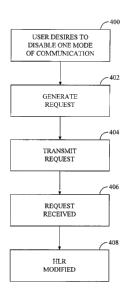
FIG. 4 illustrates the method of the present invention, shown as a
flowchart diagram. In step 400 a user of a mufti-mode wireless communication
device 100 desires to disable communications of a first mode to wireless
communication device 100. In the exemplary embodiment, the first mode is
defined as voice communications and a second mode is defined as data
communications. Often, a user will desire to prevent the first mode of
communications from being transmitted to communication device 100 if the
user will be engaged in communications of the second mode.
In step 402, a disable request to disable communications of a first mode is
generated by the user using input device 200. Typically one or more keys of a
keypad comprising input device 200 are depressed in order to generate the
request. For example, one key could be designated as a key to disable voice
communications to the communication device. Another key could be
designated to disable data communications. In another embodiment, the
request to prevent communications of a first mode could be generated
automatically by controller 202 upon a user initiating communications of a
second mode. For example, if a user initiates a data call, the request to
disable
voice communications could be generated by controller 202 automatically prior
to, or contemporaneously with, the initiation of the data call. In yet another
WO 00/78071 CA 02374813 2001-12-11 pCT/pS00/16267
embodiment, a disable request could be generated automatically by controller
202 upon initiation of communications of a second mode from a second
communication device. For example, prior to wireless communication device
100 receiving a page message of an incoming data call, an option could be set
5 using input device 200 on wireless communication device 100 to automatically
disable voice communications upon acceptance of the data communication. Or,
rather than be conditioned on the acceptance of a data communication, the
disable request could be generated automatically upon receipt of a page
message indicating the availability of an incoming data communication.
10 In step 404, the disable request to disable communications of a first
mode, including identification of the mode to be disabled and identification
information of the particular wireless communication device generating the
disable request, is transmitted by wireless communication device 100 to one or
more base stations 110, using techniques well known in the art.
15 In step 406, the disable request is received by one or more base stations
110 in communication with the wireless communication device 100 transmitting
the disable request. The disable request is then generally forwarded to MSC
120 in communication with the one or more base stations 110 comprising the
wireless communication system.
In step 406, a database associated with MSC 120 which received the
disable request is updated to disable further communications of the first mode
to wireless communication device 100. The database is generally located at
HLR 140 in communication with MSC 120. As explained above, wireless
communication devices register with MSC 120 at certain intervals in order for
MSC 120 to more efficiently control communications in the system. A data
record is created at HLR 140 indicating the presence of registering wireless
communication devices. Each data record contains at least a field of enabled
features that each registered communication device is authorized to use. In
the
exemplary embodiment, a call forwarding unconditional feature is activated for
a communication device requesting that voice communications be disabled.
The enablement of the call forwarding unconditional feature automatically
forwards all calls of a particular mode to a designated alternate phone
number,
typically to a voice mailbox system. In another embodiment, when a call is
placed to a wireless communication device having voice communications
disabled by the present invention, a "busy" signal is sent back to the
originating
device which placed the call.
Communications of a first mode will remain disabled for as long the "call
forwarding unconditional" feature or the "busy signal unconditional" feature
WO 00/78071 CA 02374813 2001-12-11 PCT/US00/16267
16
remains enabled. Communications of the disabled mode may be re-enabled in
either one of two ways. Wireless communication device 100 may generate a re-
enable request, either manually, by a wireless communication device user using
input device 200, or automatically by controller 202 detecting a predefined
event, such as the conclusion of communications of a second mode. The re-
enable request may alternatively originate with MSC 120 upon MSC 120
detecting a predefined event, such as the conclusion of communications of a
second mode.
The previous description of the preferred embodiments is provided to
enable any person skilled in the art to make or use the present invention. The
various modifications to these embodiments will be readily apparent to those
skilled in the art, and the generic principles defined herein may be applied
to
other embodiments without the use of the inventive faculty. Thus, the present
invention is not intended to be limited to the embodiments shown herein but is
to be accorded the widest scope consistent with the principles and novel
features disclosed herein.
We claim: