Note: Descriptions are shown in the official language in which they were submitted.
CA 02375762 2001-11-29
WO 00/23353 PCT/AU99/00898
A BULK CONTAINER UNLOA~ER
FIELD OF THE INVENTION
This invention relates to a bulk container unloader and
particularly relates to an apparatus which can be tipped to unload bulk
powder or granular products from a standard shipping container.
BACKGROUND ART
Shipping containers are ideal in transporting, storing and
unloading goods, as the containers are extremely robust, large, and have
standard dimensions and sizes which makes them easy to transport, lift, stack
so and store. However, transportation of bulk powder or granular products in
shipping containers has presented a problem with the unloading of the
product. Bulk powder or granular products means that the material is not
bagged but is merely poured into the container without internal linings,
equipment or fittings. Emptying such products from the container has met
with several problems including slowness in emptying, and difficulty in
accessing all parts of the inside of the container. Also, bulk powders such as
cement powder must not contact atmospheric moisture, and most current
unloading devices do result in the container contents being exposed to the
atmosphere for a considerable period of time.
2o In remote and inaccessible areas, larger concreting jobs may
require bulk cement powder to be stored for appreciable periods of time
without becoming unusable. Silo's and the like to store and dispense cement
powder are not warranted for remote jobs due to the expense in setting up.
Bulk bins can be,, used, but repeated opening of the bins to remove set
quantities of the powder can cause deterioration of the powder remaining in
the bin. Transportation to site and dispensing cement powder also presents
difficulties.
OBJECT OF THE INVENTION
The present invention is directed to an apparatus which can
3 o unload bulk containers in a manner which may overcome the
abovementioned disadvantages or provide the public with a useful or
commercial choice.
CA 02375762 2001-11-29
WO 00/23353
2
PCT/AU99/00898
In one form the invention resides in bulk container unloader
comprising a support plattorm adapted to support a bulk container which has
an outlet, a hopper associated with the outlet to receive content passing
through the outlet, and means to tilt the container to allow the container
s contents to move by gravity into the hopper. The container may be a shipping
container. The hopper may tilt with the container. The support platform and
the means to tilt the container may form part of a trailer.
In another form, the invention resides in a bulk container
unloader comprising a support platform adapted to support a shipping
to container, a hopper having an open end which is sealable relative to an
outlet
in the container and having a discharge outlet, and means to tilt the shipping
container with the attached hopper to allow the container contents to move by
gravity into the hopper.
The outlet can comprise one or more doors in the end,
15 floor, or elsewhere in the container.
In another form, the invention resides in a bulk container
unloader comprising a first support platform adapted to support a shipping
container the platform having a horizontal platform portion on which the
container can sit, and a vertical end frame portion at an outlet of the
container
2 o and which extends about the door end of the container and can be sealed
thereto, a second support platform on which the first support platform can be
supported, locking means to lock the container, the first support platform and
the second support plattorm against movement relative to each other, a
hopper having an opening, or open end which is sealable against the vertical
25 end frame or a door frame and having a discharge outlet, and means to tilt
the shipping container with the attached hopper to allow the container
contents to move by gravity into the hopper.
The outlet may be the door end of the container.
The apparatus will allow a shipping container filled with bulk
3 o powder such as cement powder to be emptied in a manner where little or no
contact with the atmosphere occurs, and the bulk powder need not be
emptied all at once. That is, the bulk powder can be discharged from the
CA 02375762 2001-11-29
WO 00/23353 PCT/AU99/00898
3
hopper on an as needs be basis, making the apparatus ideal for on-site
delivery of cement powder or other powder or granular products.
The shipping container can be of normal sizes and dimensions
and it is known to have shipping containers of different sizes, all of which
may
be applicable to the present invention. Of course, while a shipping container
is a preferred bulk container, the bulk container may consist of other than a
shipping container if such a container can be made conveniently.
The apparatus has a support platform on which the shipping
container can be supported. The support platform can be made from steel
to beams or sections. If desired, the support platform can be sized to accept
from the smallest to the largest containers, or if only one sized container
will
be used, the support platform can be made to support only one size of
container.
A hopper is provided which has an open end which can be an
open top which is sealable relative to the outlet which can be a floor door
and/or an end door of the container. That is, shipping containers are
provided with two steel swing doors on one end wall and in one form of the
invention, the hopper has an open top or open end which is dimensioned to
seal around this area such that the bulk powder or granular products in the
2 o shipping container are not unduly exposed to the atmosphere. Various types
of sealing means can be provided. For instance, the hopper can be provided
with a pneumatic or inflatable seal which seals about the outlet of the
container, which can be a floor outlet or an outlet in the end wall of the
container, or about the portion of the container through which the bulk
material will flow. Other types of sealing means are envisaged.
The hopper has a discharge outlet such that material flowing
into the hopper can be passed through the discharge outlet. The outlet can
be of conventional type and can be made closeable when not in use to
separate the material as much as possible from the atmosphere.
3 o The hopper may have means to assist in passing the material
towards the discharge outlet. The means may include conveying means,
such as a screw conveyor, an airslide, and/or paddle, or combinations thereof
CA 02375762 2001-11-29
WO 00/23353 PCT/AU99/00898
4
which assists in collecting the material passing into the hopper and conveying
it towards, and possibly though, the discharge outlet.
A pump or similar device can be provided to convey material
discharged from the outlet of the hopper to some distance away. For
instance, the pump can be used to pump the material into a storage bin. The
pump can be a peristaltic pump, vacuum conveyor, venturi, auger or belt, or
other device to transfer the product to its destination.
The apparatus includes means to tilt the shipping container
such that the container contents can move under gravity into the hopper.
to In one form, the container can be tipped with the outlet, such as
the open end, or floor mounted door of the container remaining in sealing
communication with the hopper. In another form, the container is locked to
the support platform, and the support platform is pivoted between an inclined
tipping position and a substantially horizontal rest position. The tipping can
i5 be achieved using a ram, such as an hydraulic ram, although it is envisaged
that other mechanisms can also be used, such as chains, winches, motors,
and the like.
In order to assist placement of the container onto the support
platform, one form of the invention has the container sitting on a first
support
2 o platform. The first support platform with the container can be rolled,
lifted, or
otherwise placed onto a second support platform. The first support platform
has a horizontal platform portion on which the container can sit and this can
be in the form of a steel frame arrangement. As well, the first support
platform can have a vertical end frame portion at the door end of the
25 container and which can extend entirely about the end of the container such
that the vertical end frame portion can have a pair of vertical members
extending along each side wall of the container and an upper horizontal inter-
connecting member extending over the top wall the container. The vertical
end frame can be sealingly engaged to the surround of the container and this
3 o can be achieved using various sealing means such as pneumatic or
inflatable
seals, stuffing, flaps, sealing rings, and the like.
The first support platform may have lower wheels or rollers to
CA 02375762 2001-11-29
WO 00/23353 PCT/AU99/00898
allow it to roll onto the second support platform. Rails or tracks may be
provided to assist in this action. Preferably, the container and the first
support
platform can be lifted onto a truck and then moved adjacent the second
support platform and rolled onto the second support platform.
5 The second support platform may have locking means to
securely lock the first support platform to the second support platform
against
relative movement. It is also preferred that the shipping container is
lockable
to the first support platform, although it is envisaged that it can also be
locked
directly to the second support platform.
1 o The hopper may have an open end which is sealable relative to
the vertical end frame portion on the first support platform, and in this
arrangement, a better seal may be achieved than if the shipping container
was sealed directly against the hopper.
In one form of the invention, the hopper is dimensioned such
that if the outlet of the container has openable doors (for instance a floor
door
or door on the end wall ), the doors can swing open into the hopper while
still
allowing the container contents to pass into the hopper. With this
arrangement, it is not necessary to open the container doors prior to
contacting the container with the hopper, and this can again minimize contact
2 0 of the container contents with the atmosphere.
A container door opening prevention means may be provided to
prevent the container doors) from opening too soon. That is, the container
doors can be initially securely locked by locking rods extending over the door
face, the rods being operated by a steel locking lever. Once the container is
fitted to the hopper, the steel locking lever may be difficult to access or is
inaccessible, and it is preferable that the lever can be opened and the
locking
rods disconnected prior to the container being fitted to the hopper. However,
as this can also cause the container doors to open and spill the contents, it
is
preferred that a door opening prevention means is part of the apparatus such
3 o that when the doors are unlocked, the prevention means will stop the doors
from swinging open until such time as the container is properly positioned
relative to the hopper.
CA 02375762 2001-11-29
WO 00/23353 PCT/AU99/00898
6
BRIEF DESCRIPTION OF THE DRAWINGS
Embodiments of the invention will be described with reference
to the following drawings in which
Figure 1 is a side view of an apparatus according to a first
embodiment of the invention and showing a shipping container spaced away
from the hopper.
Figure 2 illustrates the apparatus of Figure 1 where the shipping
container has been pushed against the hopper.
Figure 3 shows the apparatus in a tilted position and a
1 o horizontal position.
Figure 4 is an end view of the apparatus showing a vertical end
frame portion extending about the door end of the container.
Figure 5 illustrates a second embodiment of the invention in
plan view.
15 Figure 6 illustrates the apparatus of Figure 5 in side view.
Figure 7 shows the apparatus of Figures 5 and 6 in a tipping
position.
Figure 8 illustrates a further embodiment where the apparatus is
on a trailer making it portable.
2 o Figure 9 shows a view of conveying means in the hopper of the
apparatus of Figure 5.
Figure 10 is an end view of the embodiment of Figure 8 showing
how the semi-trailer can be stabilized.
Figure 11 is a plan view of a trailer mounted apparatus
25 according to another embodiment of the invention where the container has an
outlet on the floor.
Figure 12 is an elevation view of the trailer of Figure 11.
Figure 13 is a perspective view of the trailer of Figures 11 and
12 and illustrating the container in phantom.
3 o Figure 14 is another view of the trailer of Figures 11 and 12 and
illustrating the container in a horizontal and tipped position.
CA 02375762 2001-11-29
WO 00/23353 PCT/AU99/00898
7
BEST MODE
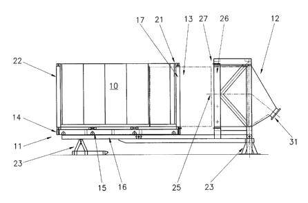
Referring to the first embodiment illustrated in Figures 1 to 4,
there is illustrated a bulk container unloading apparatus which broadly has a
shipping container 10 supported on a two part support platform 11 and where
s the container can be moved into engagement with a hopper 12. Shipping
container 10 is a conventional steel shipping container of rectangular
construction and has a door end 13 on which two heavy steel swing doors are
fitted (not shown). The doors can swing open by being attached to the
remainder of the container through steel pivot pins. The doors can be locked
to in a closed position by vertical steel rods which extend over the outside
of the
door and into upper and lower parts of the container. A steel lever is fitted
to
the rods and can be lifted to unlock the rods and therefore allow the doors to
open. These features are not illustrated and are perfectly conventional to
shipping containers.
15 In Figure 1; container 10 is initially lifted onto a first support
platform 14 which is formed from steel welded members and is made
sufficiently strong to support a fully laden shipping container 10. Support
platform 14 has lower rollers 15 to allow it to roll over second support
platform
16. The rollers can roll over rails or tracks on second support platform 16 in
2 0 order to facilitate movement of container 10 towards hopper 12.
In practice, container 12 is placed on first support platform 14
and is locked thereto typically through the usual twist locks. The container
and the first support platform can then be lifted onto a semi-trailer for
transportation to the bulk container unloading apparatus which forms part of
25 the present invention. The semi-trailer can be reversed to adjacent the end
of
the apparatus and the shipping container with the first support platform can
then be rolled from the semi-trailer onto second support platform 16. Of
course, this is preferred only and other means to put container 10 onto the
apparatus can be used.
3 o First support platform 14 has a vertical end frame portion 17
adjacent the door end of the container. End frame portion 17 is better
illustrated in Figure 4 and consists of a pair of vertically extending post
CA 02375762 2001-11-29
WO 00/23353 PCT/AU99/00898
8
members 18, 19 and a top horizontal member 20. Post members 18, 19 and
horizontal member 20 are dimensioned to extend about the outer wall of
shipping container 10. Frame portion 17 is provided with a pneumatic seal 21
which can be pneumatically inflated to seal post members 18, 19 and
horizontal member 20 against the outer walls of shipping container 10 and
adjacent door end 13. A second vertical end frame portion 22 can be
provided on the other end of the shipping container 10 and this can be
provided with a seal as well which allows the container to be placed on first
support platform either way.
to Second support platform 16 is formed from steel members
sufficiently strong to support the weight of a fully laden shipping container
and
the first support platform. Second support platform 16 is spaced above the
ground by foundations 23 with the spacing being approximately that of the
height of a semi-trailer tray such that the shipping container 10 can be
rolled
from the semi-trailer and onto second support platform 16.
When shipping container 10 is on second support platform 16,
the doors are kept shut by a door opening prevention means in the form of
power operated secondary door locks 24 (see Figure 4). These door locks 24
are extended to prevent the container swing doors from swinging open. At
2 o this stage, the primary locks which form part of the container doors can
be
opened with the doors being prevented from immediately swinging open by
secondary door locks 24 which form part of the apparatus.
Container 10 can now be moved forward against hopper 12.
Hopper 12 has an open end 25 against which the door end of the container
can pass. Hopper 12 has a sufficient internal size to allow the container
doors to swing open inside hopper 12 as the container is tipped upwardly.
The front face of the hopper has a surround frame 26 which is fitted with a
pneumatic seal 27. As first support platform 14 is rolled over second support
platform 16 and towards hopper 12, the end frame portion 17 will abut against
3 o frame 26 on hopper 12. At this stage, the first support platform can be
locked
to the second support platform against further movement and seal 27 can be
pneumatically inflated to seal frame 27 against end frame portion 17.
CA 02375762 2001-11-29
WO 00/23353 PCT/AU99/00898
9
Once in this position, the shipping container 10 can be tipped
upwardly as illustrated in Figure 3 from its lower horizontal rest position to
an
inclined tipping position where the container is inclined at approximately
60°.
To achieve this, container 10 must be securely locked to first support
platform, typically through twist locks and first support platform must be
securely locked to second support platform also by twist locks. Also, the
container frame may be locked onto the hopper. A hydraulic or pneumatic
ram 29 (see Figure 3) which is pivotally attached to a portion of foundation
23
is extended to cause second support platform 16 to pivot about pivot pin 30
to which is supported by foundation 23. As container 10 tilts upwardly, the
secondary door locks 24 are disconnected and the container doors swing
open by gravity as the container is tipped. The container can be tipped to
approximately 65° which allows the bulk powder or granular product in
the
container to slide under gravity into the hopper. The hopper can have internal
conveying means such as augers or screw conveyors (not illustrated) or
airslides to convey the bulk material to the hopper discharge outlet 31.
Outlet
31 can be fitted with a rotary valve, vacuum conveyor, venturi, auger or belt,
or other device to transfer the product to its destination.
It can be seen that with this arrangement, the contents of the
2 o container can be metered out on an as-need-be basis and either immediately
or over a prolonged period of time with little or no atmospheric contact. If
the
entire contents of the container are required, the container can be maintained
in its tilted position and the contents metered therefrom through the hopper.
If only a portion of the contents are required, the container can be tilted to
fill
the hopper, the required contents can be discharged and the container can
then be lowered back to the horizontal position. Although the container doors
stay in the open position, the seal between the container and the hopper
prevent atmospheric contamination.
Figures 5 to 7 illustrate a second simpler embodiment. In this
3 o embodiment, a base platform 35 is provided which can be made from steel
section and onto which a shipping container (not illustrated) can be placed
and locked in position using the usual twist locks 36. A vibrator 37 is fitted
to
CA 02375762 2001-11-29
WO 00/23353 PCT/AU99/00898
platform 35 and is spring loaded against the bottom of the container to assist
in the movement of compacted product through the container and to clean the
last of the product from the container.
A hopper 38 is provided adjacent the door end of the container.
5 The hopper is pivotally mounted about pivot pin 39 and can pivot clockwise
(see Figure 6) to 45° to allow the hopper to swing away while the
container is
placed onto platform 35. A ram 40 is provided to swing hopper 38 away from
and against the door end of the shipping container. When the container is on
the platform, the hopper can be hydraulically tilted back in place to seal to
the
to door end of the container. The hopper has an access door 41 which can be
opened and which allows the container doors to be unlocked. A ram 42
extends through hopper 38 and is attached to the container doors to pull the
container doors open and to hold the doors in position. (In a variation, the
container has an horizontal hatch door behind the main container doors to
prevent the powder from spilling out when the main container doors are
opened, and ram 42 is attached to this hatch door to pull it open and to hold
it
in position).
A powerful hoist 43 is fixed to a sub-frame 44 and to platform 35
and allows platform 35 to be tipped upwardly at about 65° and as
illustrated in
2 o Figure 7. In this tipping angle, the container contents can spill into
hopper 38.
Hopper 38 has a cross auger 45 with left hand flights at one end and right
hand flights on the other end and which rotates at slow revs keeping the
product clear from the sides of the hopper and directed to the outlet 46 in
the
centre of the auger. A rotating paddle 47 in the centre of the auger keeps the
2s product agitated and ensures constant feed through outlet 46.
Figures 8 and 10 show side and end views of a transportable
apparatus which is mounted to a semi-trailer. Figure 10 shows the side
support legs 48 to stabilize the trailer during the tipping process.
Figures 11-13 illustrate plan, elevation and perspective views of
3 o a bulk container unloader according to a further embodiment. The unloader
comprises a trailer 50, which allows the entire apparatus to be made portable.
Trailer 50 has an upper support platform 51 to support a container 52 (shown
CA 02375762 2001-11-29
WO 00/23353 PCT/AU99/00898
11
in phantom in Figure 13). At the rear of trailer 50 is a transversely
extending
hopper 53 having an open top. Inside hopper 53 are two counter-rotating
augers 54, 55 which will convey material towards a central lower outlet 56.
Outlet 56 communicates with the inlet 57 to a horizontally mounted peristaltic
pump 58. The peristaltic pump 58 is of the type having a central rotor which
presses against an internal flexible pump pipe. The peristaltic pump has an
outlet 59 typically fitted with a coupling to allow various devices (such as
conveying pipes) to be coupled thereto. The peristaltic pump pipe can be
approximately 100mm in diameter and the rotor can rotate at approximately
l0 32rpm. The pump is able to pump approximately 50 tonnes p/hour of the
flowable material.
Attached to inlet 57 is a fluidising means 60 which is in the form
of an air induction box. The box has an air inlet which is connected to a
pressure hose and ultimately to a source of compressed air. The compressor
supplies air at approximately 10KPa as a high volume low pressure source of
air. The air passes into the induction box and into a longitudinal tube which
has a nylon webbing on the top. The box has an outlet which is coupled to
the pump inlet.
In use, the peristaltic pump is started which causes a suction to
2 o form at the inlet. High volume low pressure air is passed into the
induction
box and at the same time, the outlet 56 of the hopper is opened. The pump
sucks material from the hopper outlet and into the air induction box, and as
the solid material passes through the box, it becomes fluidised by the air and
adopts an at least partially fluid nature. At this stage, pump 58 can
efficiently
2s pump the dry particulate matter through the pump and through outlet 59. A
conduit (not shown) can be attached to the outlet to allow the material to be
pumped into a holding tank, silo or to any other suitable destination. There
is
very little dust associated with the pumping and therefore large dust
collectors
are not required.
3 o Container 52 in this embodiment has a door in the bottom floor
of the container (not illustrated) which overlies the open top of hopper 53
when the container is supported on the trailer. The bottom door can be
CA 02375762 2001-11-29
WO 00/23353 PCT/AU99/00898
12
opened such that powder initially falls through the door, into the hopper to
be
conveyed by augers 54 through outlet 56. As the container becomes partially
emptied, it can be slowly tipped upwardly to allow more of the powder to fall
through the open floor mounted door of the container. The hopper 54 also
pivots with the container such that no appreciable air gap is formed between
the two.
Figure 14 is another view of the bulk unloader showing a
shipping container in a horizontal position and in an inclined tipped
position.
It can be seen that hopper 53 is connected to the tipping chassis 62 and thus
to stays in a fixed position relative to the container 52 as the container is
tipped.
It should be appreciated that various other changes and
modifications can be made to the embodiments described without departing
from the spirit and scope of the invention.