Note: Descriptions are shown in the official language in which they were submitted.
CA 02376042 2001-12-07
WO 00/74985 PCT/US00/15636
ELECTRONIC TRAILER HAND CONTROL
Background of the Invention
This invention pertains to the art of control
valves, and more particularly to a control valve used in a
pneumatic or air brake system.
The invention is particularly applicable to a
manually operated control valve that provides selective,
graduated control of service brake air pressure in a tractor
trailer combination. However, it will be appreciated that
the invention may have wider applications and be
advantageously employed in related environments and
applications.
Brake systems for heavy vehicles typically employ
a pneumatic system in which an air compressor charges a
supply reservoir and actuation of a control valve
selectively provides air pressure to one or more brake
chambers associated with the tractor trailer. In the
particular environment and embodiment at issue here, the
manually operated control valve is mounted inside the
operator's cab, for example, inside the steering column or
is clamped to the exterior of the column. Thus, pneumatic
lines extend to and from the control valve so that selective
application of service brake air pressure to the trailer
brake chambers is provided upon demand by the vehicle
operator or driver. For exarrupl_e, when descending through a
steep grade, the driver may opt to actuate the control valve
in order to provide selective braking to the trailer brakes.
Thus, depending on the degree of valve handle rotation, the
brakes may be gradually applied over a range of operation.
Known trailer control brake valves are usually biased to a
first or closed position so that in the absence of an
actuating force, air pressure is not provided to the brakes.
Although trailer control brake valves for
pneumatic brake systems are well known in the art, the
industry continues to develop toward increased electronic
control of the tractor and trailer service brakes. This
necessitates modification of the current pneumatic trailer
SUBSTITUTE SHEET (RULE 26)
CA 02376042 2001-12-07
WO 00/74985 2 PCT/US00/15636
control brake valve so that it is compatible with an
electropneumatic system. Because of the familiarity and
acceptance of known trailer control brake valves in the
pneumatic environment, any modified brake valve for an
electropneumatic system must offer at least the same
benefits and advantages in a similar manner.
Accordingly, a need exists for a new and improved
control brake valve for a trailer that is compatible with an
electropneumatic system and provides a reliable, simple, and
economical product.
Summary of the Invention
The present invention contemplates a new and
improved trailer control brake valve that may be operated in
first and second positions, and intermediate positions, to
provide selective, graduated application of the service
brakes to a trailer.
According to a preferred embodiment of the
invention, an actuating handle extends from a housing and is
adapted for selective rotation by an operator. The handle
is biased toward a first or non-actuated position. A
position sensor or potentiometer mounted to the housing is
operatively driven by the actuating handle and provides an
electrical signal indicative of movement of the actuating
handl a .
According to another aspect of the invention,
positive first and second stops are provided to limit
movement of the actuating handle between release and fully
applied positions.
According to another aspect of the invention, a
detent arrangement holds the actuating handle against the
biasing force at an intermediate position.
A principal advantage of the invention is the
elimination of pneumatic lines into the operator cab for
effecting trailer hand brake application.
SUBSTITUTE SHEET (RULE 26)
CA 02376042 2001-12-07
WO 00/74985 3 PCT/US00/15636
Another advantage of the invention resides in the
faster braking response associated with the electropneumatic
system.
Yet another advantage of the invention is the
ability to program the trailer braking control to
accommodate various trailer brake systems.
A further advantage of the invention is realized
by the reduced size of the assembly.
Still other advantages and benefits of the
invention will become apparent to those skilled in the art
upon a reading and understanding of the following detailed
description.
Brief Description of the Drawings
The invention may take physical form in certain
parts and arrangements of parts, preferred embodiments of
which will be described in detail in this specification.
The invention is illustrated in the accompanying drawings
which form a part of the invention, and wherein:
FIGURE 1 is a schematic representation of a
typical, prior art pneumatic truck/tractor air brake system;
FIGURE 2 is a longitudinal cross-sectional view of
a first preferred embodiment of an electronic trailer hand
brake assembly in accordance with the subject invention;
FIGURE 3 is a top plan view thereof;
FIGURE 4 is an exploded perspective view of a
second preferred embodiment;
FIGURE 5 is a perspective view of the embodiment
of FIGURE 4;
FIGURE 6 is a longitudinal cross-sectional view of
a third preferred embodiment;
FIGURE 7 is a top plan view of the FIGURE 6
embodiment;
FIGURE 8 is a longitudinal cross-sectional view of
yet another embodiment; and,
SUBSTITUTE SHEET (RULE 26)
CA 02376042 2001-12-07
WO 00/74985 PCT/US00/15636
4
FIGURE 9 is a graphical representation of a
preferred relationship between rotational input through the
handle and the output voltage.
Detailed Description of the Preferred Embodiments
Referring now to the drawings wherein the showings
are for purposes of illustrating the preferred embodiments
of the invention only, where the drawings are not intended
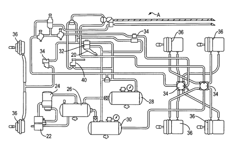
to limit the invention, the FIGURES show a brake system A of
l0 the type used for heavy vehicles such as tractor-trailer
combinations. More particularly, and with reference to
FIGURE l, a prior art brake system is schematically
represented. The structure and operation of these systems
are well known in the art; however, a brief review of the
IS overall system is helpful in understanding the present
invention. The braking system A is a pneumatic, or air,
brake system in which a pedal or treadle 20 mounted in the
truck cab (not shown) is selectively depressed by the
operator. Pressurized air from a compressor 22 passes
20 through an air dryer 24 and is stored in supply reservoir 26
which, in turn, supplies a front axle service reservoir 28
and a rear axle service reservoir 30. A dual control valve
32 is actuated by the foot pedal to provide air pressure
from the reservoirs to valves 34 associated with the front
25 and rear axles. These valves control the application of air
pressure to brake chambers 36 associated with the individual
wheels.
Also illustrated in FIGURE 1 is a conventional
trailer control brake valve 40. It is a manual or hand-
30 operated control valve that provides graduated application
of service brake air pressure to the trailer. A handle
extends from the valve housing and provides for selective
application of air pressure to the trailer brakes. As will
be appreciated, since the trailer control brake valve of the
35 conventional pneumatic system is typically mounted in the
cab, provision must be made for a supply line, a delivery
line, etc. Neither of these components is very flexible and
SUBSTITUTE SHEET (RULE 26)
CA 02376042 2001-12-07
WO 00/74985 PCT/US00/15636
thus difficulties are presented in mounting the components
in the truck cab. Moreover, although the valve is very
robust, its size presents its own mounting problems and thus
limits flexibility in accommodating the valve in the truck
5 cab without adversely impacting on other components.
FIGURES 2 and 3 illustrate a preferred embodiment
of the present invention. Particularly, these FIGURES show
an electronic trailer hand control valve assembly 50 that
provides an electrical signal to an electronic control unit
l0 (ECU) representative of the position of the actuating
handle. Accordingly, instead of a pneumatic system, this
arrangement is designed for an electropneumatic system where
a position sensor or potentiometer associated with the hand
control valve eliminates relatively inflexible supply and
delivery lines associated with the prior pneumatic systems.
Moreover, the electrical signal also has the advantage of
allowing the output to be programmed or changed to alter the
characteristics of the output curve. For example, an
angular position of an actuating handle on one truck may
provide a first pressure, e.g. 20 psi, but when mounted on
another trailer, will provide a second pressure, e.g. 50
psi. Conversion to an electrical braking or
electropneumatic system of the present invention, however,
allows the curve characteristics to be altered in the ECU
without disturbing the remaining components of the braking
system.
The assembly includes a housing 52, having an
internal cavity 54 that receives a drive shaft 56, biasing
spring 58, and a position sensor 60. The housing can be
formed as a multi-component assembly or, alternatively, it
may be an integrally molded component to eliminate parts
inventory and reduce costs associated with assembly. In the
illustrated embodiment, the spring 58 is received in the
housing cavity 54. A first end 62 of the spring is received
in a recess of the housing to secure it against rotation. A
second end 64 of the spring abuts against a portion of the
drive shaft assembly, shown here as a spring return pin 66.
SUBSTITUTE SHEET (RULE 26)
CA 02376042 2001-12-07
WO 00/74985 ~ PCT/US00/15636
Again, as will be appreciated, in select embodiments, the
drive shaft may be formed as a single component so that a
projection or recess is adapted to receive the second end of
the spring 64 to impart a biasing force to the assembly in a
manner to be described further below.
The drive shaft is received in the housing cavity
and adapted for free rotational movement therein. In the
illustrated embodiment, the drive shaft 56 includes a
shoulder 70 received on a shoulder 72 of the housing. A
first or upper end of the drive shaft includes an attachment
assembly 74 that permits convenient connection with
actuating handle 80. As will be appreciated by one skilled
in the art, any number of actuating handles 80 can be used
as desired by the end user, so that the illustrated handle
is merely exemplary of one arrangement. A relatively simple
screw assembly can be used as a preferred means for securing
the handle to the drive shaft. Alternatively, other
connecting or securing arrangements can be used or the
handle can be integrally formed with the drive shaft if so
desired. A retaining ring 82 is received in an associated
groove 84 of the housing to maintain the drive shaft in
mounted relation when all of the components are assembled in
the housing. A second, or lower end 86 of the drive shaft
is operatively connected to the position sensor or
potentiometer 60 in any convenient manner. Here, a lower
end of the shaft includes a recess 88 that receives a pin 90
extending from the position sensor. The pin and drive shaft
are secured together to rotate as a unit, i.e, no relative
rotation, so that movement of the handle 80 between stops
92, 94 provides rotational movement of the drive shaft,
overcoming the spring biasing force, and providing an
angular or rotational input to the position sensor. In a
manner well known in the art, the position sensor 60, such
as a potentiometer, outputs an electrical signal dependent
on the movement of the actuating handle, here, the
rotational movement of the handle. Signals output through
connecLOr 100 thus require that only a single connection
SUBSTITUTE SHEET (RULE 26)
CA 02376042 2001-12-07
WO 00/74985 ~ PCT/US00/15636
extends outwardly from the electronic trailer hand control.
Moreover, the wire associated with the connector is flexible
enough, and small enough, to be easily accommodated in the
cab. If the operator releases the actuating handle, the
spring 58 urges the handle toward the first stop to a non-
actuated position. Otherwise, the degree of angular
movement of the actuating handle, and thus the drive shaft,
provides a variable signal via the potentiometer to mimic
the operation of the prior art pneumatic counterpart.
l0 As best illustrated in the embodiment of FIGURES 4
and 5, the assembly is substantially similar to that
described above so that like numerals with a primed suffix
(') will reference like components, and new numerals will
identify new components. In this arrangement, the
electronic trailer hand control valve assembly 50' further
includes a detent 110 so that a desired intermediate
position of the actuating handle can be maintained. A
conventional ball detent extends through the sidewall of the
housing 52' and the ball member 112 is adapted to cooperate
with enlarged surface 114 of the shoulder. By depressing
the detent, the ball 112 engages the shoulder 114 and
applies a radial force that is sufficient to oppose the
return or biasing force of the spring 58'. This allows the
actuating handle 80' to be maintained at an intermediate
position while the driver or operator completes, for
example, a walk-around inspection of the trailer.
The embodiment of FIGURES 6 and 7 illustrates yet
another arrangement for holding the electronic trailer
control in a desired intermediate position. Again, where
possible, like components are referenced by like numerals
with a double prime suffix (") and new components are
identified by new numerals for ease of illustration and
understanding. Rather than using the detent mechanism of
FIGURES 4 and 5, the actuating handle 80" is modified to
provide a selective locking arrangement. A positioning
mechanism 120, shown as a generally L-shaped arm, is adapted
for selective radial movement. A first or inner end thereof
SUBSTITUTE SHEET (RULE 26)
CA 02376042 2001-12-07
WO 00/74985 PCT/US00/15636
8
122 selectively engages serrations or teeth 124 provided on
an external surface of the housing. Thus, the serrations
and positioning mechanism operate as a ratchet mechanism.
To actuate the locking assembly, a button 126 is
depressed (in a radial direction) to urge the positioning
mechanism radially inward against biasing spring 130. The
torsional force imposed by the spring 58" rotates the handle
sufficiently to lock the handle end 122 against the teeth
124. To release the handle from the locked angular
position, the button includes an enlarged shoulder 132 that
can be manually grasped by the operator and the radial
outward force of spring 130 aids in the release function.
In this manner, the button is depressed and the positioning
mechanism locks the positioning handle at the desired
rotational position. This position is maintained until the
button is pulled outward whereby the restoring force of the
torsion spring urges the actuating handle of the valve
toward its first stop 92.
The embodiment of FIGURE 8 has a number of
similarities to the embodiment described with respect to
FIGURES 6 and 7; however, the output is linear rather than
the angular sensor previously described. Thus, only the new
components are highlighted below and one skilled will
readily recognize that the remaining components is
structurally and functionally similar unless specifically
noted otherwise. A cam 150 is secured to and rotates with
the handle. A tapered or inclined lower cam surface 152
cooperates with a cam follower 154 which is adapted for
axial motion along the axis of rotation of the handle in
response to angular movement of the cam. The torsion spring
urges the cam follower into operative abutting engagement
with the cam. In addition, a linear position sensor 160
includes a stem 162 that protrudes axially therefrom for
engagement with the cam follower. Thus, as the cam follower
is urged axially downwardly (as shown), the stem is
compressed and a suitable proportional signal representative
of the amount of linear movement of the stem is output.
SUBSTITUTE SHEET (RULE 26)
CA 02376042 2001-12-07
WO 00/74985 9 PCT/US00/15636
Still other linear sensor configurations~can be used with
equal success and without departing from the scope and
intent of the subject invention.
FIGURE 9 illustrates that the sensor can include
multiple outputs. For example, switches can be incorporated
into the position sensor so that in response to an angular
or linear input, discrete signals or output voltages are
obtained. Line 170 provides, for instance, an indication
that the handle has been sufficiently moved to apply an
l0 output pressure. Likewise, line 172 indicates that no
further pressure will be applied. Line 176, on the other
hand, represents the potentiometer output that provides a
desired proportion of ratio output in response to an
operator input through the handle, either as a linear or
angular input.
The invention has been described with reference to
the preferred embodiments. Obviously, modifications and
alterations will occur to others upon a reading and
understanding of this specification. It is intended to
include all such modifications and alterations in so far as
they come within the scope of the appended claims or the
equivalents thereof.
SUBSTITUTE SHEET (RULE 26)