Note: Descriptions are shown in the official language in which they were submitted.
CA 02376560 2001-12-06
WO 00/76574 PCT/US00/16121
BACKGROUND OF THE INVENTION
IMPLANTER APPARATUS
1. Field of the Invention.
The present invention relates, generally, to apparatus and methods for
implanting objects beneath membranes. More particularly, the invention relates
to
implanters for depositing electronic tracing devices, hormone pellets or other
objects
or pellets beneath a membrane.
2. Background Information.
The state of the art in general includes various devices and methods for
implanting objects beneath a membrane using a device that has a rod which
travels
through a hollow needle to deposit the object through the needle and beneath
the
punctured membrane. For example, the objects or pellets may comprise
electronic
tracing devices or transponders which are used to tag an animal, or the
pellets may
comprise hormone pellets which are used in the domestic livestock fattening
industry
to promote growth of the animal. The pellets are often injected into the ears
of the
animals to prevent the pellets from entering food products for human or animal
consumption as the ears are commonly discarded in slaughtering. Typically, the
ear is
grabbed with one hand while the other hand operates the implanter. The pellets
should be carefully, properly and accurately implanted to reduce the
probability for
infection and increase the effectiveness of the deposited pellets. Further,
because of
the movements of the animals, it is desirable for the pellets to be quickly
implanted
into the animal.
These devices and methods are believed to have significant limitations and
shortcomings. One of the shortcomings is that implanter devices may spread
blood-
CA 02376560 2007-06-26
2
borne diseases among the animals if the needle is not replaced for each
animal. In
recognition of this problem, Turely (U.S. Patent No. 5,279,554) disclosed a
device
that uses a shroud or covering that moves and locks in an extended position to
partially cover the needle, and thus encourages a user to replace the needle
after each
use. Another shortcoming of the known art is the inability to automatically,
quickly,
consistently and powerfully implant multiple pellets. Turley (U.S. Patent No.
4,154,239)
disclosed that the link between the drive pin and the trigger/actuator in the
known art
devices tended to buckle, and further disclosed that the speed or velocity of
the drive pin
was limited because the known art devices employed a 1:1 ratio between the
drive pin and
the trigger/actuator. In recognition of these problems, Turley ('239)
disclosed a device that
uses a flexible belt or link to achieve a velocity ratio other than 1:1. Other
devices have
achieved a velocity ratio other than 1:1 by attaching spur gears to the
trigger and a rack
gear to the drive pin.
Applicants' invention provide an implanter apparatus which is believed to
constitute an improvement over existing technology.
CA 02376560 2001-12-06
WO 00/76574 PCTIUSOO/16121
3
BRIEF SUMMARY OF THE INVENTION
The present invention provides an implanter which generally comprises a
housing or housing assembly, a hollow needle connected to the housing assembly
through a quick attachment mechanism, a drive pin positioned within the
housing
assembly and aligned with the hollow needle, and a trigger assembly operably
connected to both the housing assembly and the drive pin. The drive pin has a
distal
end, and further has a retracted position in which the distal end of the drive
pin is in
the housing assembly and an extended position in which the distal end of the
drive pin
extends out of the housing assembly. A pellet is positioned between the needle
and
the distal end of the drive pin when the drive pin is in the retracted
position. The
drive pin expels the pellet through the hollow needle as it moves from the
retracted
position to the extended position.
The trigger assembly includes a trigger that has a relaxed position and an
actuated position. The drive pin moves from the retracted position to the
extended
position to expel the pellet when the trigger moves from the relaxed position
to the
actuated position. The trigger assembly is adapted to provide a mechanical
advantage
for increasing the velocity of the drive pin with respect to the velocity of
the trigger.
The trigger assembly includes a trigger lever having a fulcrum point, a
trigger end
operably contacting the trigger, and a shuttle end operably connected to a
drive pin
shuttle that slides along at least one shuttle guide groove to move the drive
pin
between the retracted position and the extended position. The fulcrum point is
preferably closer to the trigger end than to the shuttle end to provide the
mechanical
CA 02376560 2001-12-06
WO 00/76574 PCTIUSOO/16121
4
advantage for increasing the velocity ratio between the drive pin and the
trigger
assembly.
The housing assembly includes a magazine housing attached to a body
housing. The magazine housing has a magazine passage sized to receive a pellet
magazine and contains a magazine advancement mechanism. The magazine
advancement mechanism indexes the pellet magazine through a number of
predeterniined index positions within the magazine passage. The drive pin is
adapted
to extend through the pellet magazine, i.e. one of the plurality of tubes, and
into the
hollow needle at each one of the predetermined index positions. The magazine
advancement mechanism preferably has an opening or window for viewing the
index
positions of the pellet magazine. The magazine advancement mechanism has at
least
one fixed clip for engaging one side of the pellet magazine, at least one
movable clip
for engaging the other side of the pellet magazine, and an index actuator for
indexing
the at least one movable clip within the magazine passage. The clips are
adapted to
prevent the pellet magazine from moving in a first direction within the
magazine
passage and to allow the pellet magazine to move in a second direction upon
the
application of an index force, which moves the movable clip in an index
motion. The
movable clip has a bias spring to move the movable clip from one groove, over
a
ridge, and to an adjacent groove upon release of an index force.
In a manual index actuator embodiment, the index force is manually applied to
the index actuator to index the movable clip within the magazine passage. A
bias
spring provides the return motion. In an automatic index actuator embodiment,
the
index force is generated by an actuation force applied to the trigger. The
automatic
index actuator includes a cam lever pivotally attached at a fulcrum point to
the
CA 02376560 2001-12-06
WO 00/76574 PCT/USOO/16121
housing assembly. The cam lever has a cam end in operable contact with a cam
follower mounted on the drive pin shuttle. The cam lever further has a
magazine
advancement mechanism end in operable contact with the at least one movable
clip.
The magazine advancement end has an index motion and a return motion. The cam
5 lever pivots and moves the magazine advancement end in an index motion to
index
the pellet magazine when the cam follower moves with the drive pin into the
retracted
position. and the cam lever pivots and moves the magazine advancement end in a
return motion as the cam follower moves with the drive pin from the retracted
position
toward the extended position. A latch mechanism prevents the magazine
advancenlent end from undergoing an index motion until the drive pin is fully
retracted out of the magazine.
Each one of the tubes in the pellet magazine may include both a pellet and a
plug. The pellet is positioned in front of the plug. When the drive pin
extends, the
pellet is expelled from the needle and the plug remains in the needle to
discourage the
use of the needle in another animal. The quick attachment mechanism allows the
needle to be quickly replaced. Preferably, the quick attachment mechanism
includes a
threaded collet. The hollow needle extends through the threaded collet, and a
threaded nut screws around the collet to quickly attach and detach the hollow
needle
from the housing assembly. The collet preferably has two or more
circumferencially
spaced slots that enable the collet to securely tighten around a range of
needle
diameters.
The features, benefits and objects of this invention will become clear to
those
skilled in the art by reference to the following description, claims and
drawings.
CA 02376560 2001-12-06
WO 00/76574 PCT/US00/16121
6
BRIEF DESCRIPTION OF THE SEVERAL VIEWS OF THE DRAWING
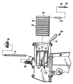
Figure 1 is a perspective view of an embodiment of the implanter of the
present invention.
Figure 2 is a rear plan view of the implanter of Figure 1.
Figure 3 is a partially exploded view of a quick attachment mechanism for a
needle, a magazine housing, and of a pellet magazine having a tube loaded with
both a
pellet and a plug.
Figure 4 is a perspective view of a pellet magazine.
Figure 5 is a plan view, partially in cross section, of a drive pin extending
through a pellet magazine and a needle.
Figure 6 is a plan view of a magazine advancement mechanism illustrating a
manual index actuator.
Figure 7 is a plan view of a partially assembled housing assembly illustrating
the relationship between a trigger assembly, a drive pin and a drive pin
shuttle when
the drive pin is in a retracted position.
CA 02376560 2001-12-06
WO 00/76574 PCT/USOO/16121
7
Figure 8 is a plan view of partially assembled housing assembly illustrating
the relationship between a trigger assembly, a drive pin and a drive pin
shuttle when
the drive pin is partially extended.
Figure 9 is a rear view of a magazine advancement mechanism illustrating a
manual i ndex actuator.
Figure 10 is an end view illustrating the relationship between a pellet
magazine and a magazine advancement mechanism.
Figure 11 is a perspective view of another embodiment of the implanter gun of
the present invention.
Figure 12 is a plan view of a partially assembled housing assembly
illustrating
an autonlatic index actuator and a latched cam actuated lever.
Figure 13 is a plan view illustrating the placement of a pellet magazine
within
a magazine passage of a magazine advancement mechanism.
Figure 14 is a plan view of a partially assembled housing assembly
illustrating
an autonlatic index actuator and a released cam actuated lever.
Figure 15 is a rear plan view of the automatic index actuator of Figure 14 and
the latclied cam actuated lever.
CA 02376560 2001-12-06
WO 00/76574 PCTIUSOO/16121
8
Figure 16 is a rear plan view of the automatic index actuator of Figure 14 and
a released cam actuated lever.
DETAILED DESCRIPTION
Figures 1-16 illustrate preferred embodiments of the present invention, which
is generally indicated by the reference numeral 10. The implanter 10 is
described
below tii-st in terms of its major structural elements and then in terms of
its secondary
structural and/or functional elements which cooperate to implant an object
beneath a
membra e, i.e. to inject a transponder or hormone into an animal or to deposit
a
reactant through a stretched covering into a reaction vessel, among others.
Referring to Figures 1, 3, 5, 7 and 8, the implanter 10 generally comprises a
housing assembly 12, a hollow needle 14 connected to the housing assembly 12,
a
drive pin assembly 16 including a drive pin 18 positioned within the housing
assemblv 12 and aligned with the hollow needle 14, and a trigger assembly 20
operably connected to both the housing assembly 12 and the drive pin 18. The
drive
pin 18 has a distal end 22, and further has a retracted position in which the
distal end
22 of the drive pin 18 is in the housing assembly 12 and an extended position
in which
the distal end 22 of the drive pin 18 extends out of the housing assembly 12
and
through the hollow needle 14.
Referring to Figures 3 and 5 in particular, a pellet 24 is positioned,
preferably
using a pellet magazine 26, between the needle 14 and the distal end 22 of the
drive
CA 02376560 2001-12-06
WO 00/76574 PCT/US00/16121
9
pin 18 v'rhen the drive pin 18 is in the retracted position. The drive pin 18
expels the
pellet 24 through the hollow needle 14 as it moves from the retracted position
to the
extended position. The trigger assembly 20 includes a trigger 28 that has a
relaxed
position shown in Figure 7, and an actuated position shown in Figure 8. The
drive
pin 18 moves from the retracted position to the extended position as the
trigger 28
moves fi-om the relaxed position to the actuated position. The trigger
assembly 20 is
adapted to provide a mechanical advantage for increasing a drive pin velocity
with
respect to a trigger velocity, which provides the implanter 10 with the
capability of
quickly ciepositing an object or pellet 24. The embodiments illustrated in the
figures
incorporate a first class lever as a trigger lever 30 to provide the
mechanical advantage
that increases the drive pin velocity.
Tlie pellet magazine 26 has a plurality of tubes 32 for holding and retaining
pellets 24. The housing assembly 12 includes a magazine passage 34 sized to
receive
the pellet magazine 26 and contains a magazine advancement mechanism 36 for
indexing the pellet magazine 26 through a number of predetermined index
positions
within the magazine passage 34. The drive pin 18 is adapted to extend through
the
pellet magazine 26 and into the hollow needle 14 when the pellet magazine 26
is at
each one of the predetermined index positions. A pellet 24 may be loaded in
front of
a plug 38 in each one of the tubes 32 in the pellet magazine 26. The pellet 24
is
positioned and adapted to be expelled from the needle 14, and the plug 38 has
a shape
and size to remain in the needle 14 when the drive pin 18 is extended. By
remaining
in the needle 14, the plug 38 discourages, and effectively prevents, the
hollow needle
14 from being used again in another animal. The plug 38 may be formed from a
variety of materials. In the embodiment shown in the figures, the plug 38 is a
plastic
CA 02376560 2001-12-06
WO 00/76574 PCT/USOO/16121
object having a generally cylindrical shape. The plug 38 has a circumferencial
rib 39
that causes the plug 38 to be stuck in the needle 14.
Tlie elements of the implanter 10 are hereafter described in more detail. Many
of these elements or components are constructed from molded plastic in order
to
5 provide an economical implanter 10 that is light and durable. Referring
again to
Figure 1, the housin(ir assembly 12 generally includes a body housing 40
attached to a
magazine housing 42. In the embodiments shown, the body housing 40 is formed
by
fastenin' a first side 40a to a second side 40b, and the magazine housing 42
is formed
by fastening together a first side 42a to a second side 42b. The body housing
40 is
10 shaped generally like a pistol, which provides a user the ability to
operate the device
and accurately deposit the pellet with one hand. The body housing 40 comprises
a
hand gri 1) portion 44 and a drive pin portion 46. The trigger assembly 20,
and in
particular the trigger 28, is positioned adjacent to the hand grip portion 44.
Referring
to Figut-e 7 and 8, the drive pin portion 46 is formed to include a drive pin
passage 48
and a shuttle guide, which is formed by shuttle guide grooves 50 in the first
and
second sides 40a and 40b of the body portion 40. A drive pin shuttle 90 is
connected
to the pi-oximal end of the drive pin 18, and slides along the shuttle guide.
The shuttle
guide and the drive pin passage 48 cooperate to accurately extend the drive
pin 18
through the pellet magazine 26 and the hollow needle 14.
I'he first and second sides 42a and 42b of the magazine housing 42 form the
magazinc passage 34, which is sized and configured to receive the pellet
magazine 26
shown in Figure 4. The pellet magazine 26 comprises a plurality of adjacent
tubes 32
formed together as a unitary body. The longitudinal axes of these tubes are
parallel to
each other and are generally aligned in the same plane. The pellet magazine 26
has
CA 02376560 2001-12-06
WO 00/76574 PCT/US00/16121
11
two exterior sides 52a and 52b, each of which have a set of parallel ridges 54
and
corresponding grooves. The pellet magazine 26 further has a proximal end 56
and a
distal end 58. An alignment flange 60, having a generally rectangular plate-
like
shape, is formed at the proximal end 56 and serves as a means for properly
aligning
and orieiltating the pellet magazine 26 in the magazine passage 34. A lip
having
circumi'crencial cuts is formed around the circumference of each tube 32 at
the distal
end 58. l'lle lip prevents the pellets 24 from falling out of the pellet
magazine 26, but
allows the drive pin 18 to easily force a pellet 24 through the lip. As
illustrated in
Figure 13, the alignment flange 60 of the pellet magazine 26 corresponds to
alignment grooves 62 formed in each side of the magazine housing 42 and causes
the
pellet mLigazine 26 to fit within the magazine passage 34 only in the
predetermined
manner.
A quick attachment mechanism 64 for a needle 14 is mounted on the distal
side of the magazine housing 42. As illustrated in Figures 1 and 6, the quick
attachnicnt mechanism 64 preferably includes a threaded collet 66 or slotted
sleeve.
The hollow needle 14 extends through the threaded collet 66, and a threaded
nut 68
screws Lii-ound the collet 66 to quickly attach and detach the hollow needle
14 from
the housing assembly 12. The collet 66 preferably has two or more
circumferencially
spaced slots 70 that enable the collet 66 to securely tighten around a large
range of
needle diameters. The collet 66 shown in the figures, for example, has six
circumferencially spaced slots 70. The collet 66 is mounted to the magazine
housing
42 by sandwiching the housing wall between two nuts.
The magazine housing 42 contains the magazine advancement mechanism 36
for indexing the pellet magazine 26. The magazine advancement mechanism 36
CA 02376560 2001-12-06
WO 00/76574 PCT/US00/16121
12
includes: at least one and preferably two fixed clips 72 for engaging one side
of the
pellet magazine; at least one and preferably one movable clip 74 for engaging
the
other sicle of the pellet magazine; and an index actuator 76 for indexing the
movable
clip 74 \%-ithin the magazine passage 34. The clips 72 and 74 are attached to
the
magazine housing 42 within the magazine passage 34. As illustrated in Figure
10,
the clips 72 and 74 are adapted to prevent the pellet magazine 26 from moving
in a
first dii-ection and to allow the pellet magazine 26 to move in a second
direction upon
the application of an index force by securely engaging the ridges 54 in the
side walls
of the pellet magazine 26. The movable clip 74 has a bias spring 78 and a
latch spring
80 to move the movable clip 74 from one groove over a ridge 54 to another
adjacent
groove upon release of the index force.
I n manual index actuator embodiment 76a illustrated in Figures 1, 2, 6, and
9,
the index force is manually applied to the index actuator 76 to index the
movable clip
74 witliin the magazine passage 34. The bias spring 78 provides the return
motion. In
an automatic index actuator embodiment 76b illustrated in Figures 11-15, the
index
force is -,enerated by an actuation force applied to the trigger 28. The
automatic index
actuator 76b includes a cam lever 82 pivotally attached at a fulcrum point 84
to the
body housing 40b. The cam lever 82 has a cam end 86 in operable contact with a
cam
follower 88 mounted on a drive pin shuttle 90, which is attached to the drive
pin 18.
The cam lever 82 further has a magazine index end 92 in operable contact with
the
movablc clip 74. The magazine index end 92 has an index motion and a return
motion. As illustrated in Figures 12 and 15, the cam lever 82 pivots and moves
the
magazine index end 92 in a return motion as the cam follower 88 moves with the
drive pi 18 from the retracted position toward the extended position. As
illustrated
CA 02376560 2001-12-06
WO 00/76574 PCTIUSOO/16121
13
in Figures 14 and 16, the cam lever 82 pivots and moves the magazine index end
92
in an inclcx motion when the cam follower 88 moves with the drive pin shuttle
90 and
drive pin 18 into the retracted position. A latch mechanism 94, comprising a
latch
member 96 pivotally mounted to the body housing 40 and a latch spring 98 for
biasing
the latch inember 96 in a latch position, prevents the magazine index end 92
from
undergo i ng an index motion until the drive pin shuttle 90 contacts the latch
member
96, presscs against the latch spring 98, and pushes the latch member 96 to a
release
position. The drive pin 18 is fully retracted out of the magazine 26 when the
drive pin
shuttle 90 contacts the latch member 96. The latch member 96 releases a pair
of bias
springs 78, shown in Figure 16, which provide an index force to index the
pellet
magazinc 26. The drive pin 18 is securely attached to the drive pin shuttle
90, and
together lorm the drive pin assembly 16 that cooperates with the drive pin
passage 48
and shuttle guide in the body housing 40 to consistently and accurately extend
and
retract thc drive pin 18 along a line extending through the pellet magazine
tubes 32,
the col let 66, and the hollow needle 14. The index position of the pellet
magazine 26
is seen through an opening or window 100 in the magazine housing 42.
"I'lie trigger assembly 20 is adapted to provide a mechanical advantage for
increasino a drive pin velocity with respect to a trigger velocity, and thus
allow the
implantci- 10 to quickly deposit the pellet. The embodiments illustrated in
Figures 7,
8, 12 and 14 incorporate a first class lever 30, wherein the effort or
actuation force is
applied it the trigger 28 and the load is applied at the drive pin shuttle 90,
to provide
the meclianical advantage to increase the drive pin velocity. The trigger
assembly 20
includes the trigger lever 30 which has a fulcrum point 102, a trigger end 104
operablN contacting or connected to the trigger 28, and a shuttle end 106
operably
CA 02376560 2001-12-06
WO 00/76574 PCT/US00/16121
14
connected. through a trigger linkage 118, to the drive pin shuttle 90 that
slides along
the shuttle guide grooves 50 to move the drive pin 18 between the retracted
position
and the extended position. The fulcrum point 102 is preferably closer to the
trigger
end 104 than to the shuttle end 106 to provide the mechanical advantage to
increase
the velocity ratio between the drive pin 18 and the trigger 28. A cam follower
108 is
connectcd at the trigger end 104 of the trigger lever 30 and a cam surface 110
is
formed i n the interior of the trigger 28. The trigger 28 is attached to the
body housing
40 at a],ivot point 112. The trigger 28 pivots about this point 112 upon the
application of an actuation force. The cam surface 110 within the trigger 28
is formed
to cause the cam follower 108 and the trigger end 104 to pivot back toward the
hand
grip poi-tion 44, which causes the shuttle end 106 to pivot forward to extend
the drive
pin 18. A trigger bias spring 114 is attached between the trigger lever 30 and
a spigot
116 in thc hand grip portion 44 of the body housing 40 to bias the shuttle end
106 and
the drive pin shuttle 90 in the retracted position. The force of the trigger
bias spring
114 is sufficient to overcome the force of the latch spring 98.
1 he inlplanter 10 described above is used to implant an object 24 beneath a
membi-ane. The niethod for implanting an object 24 beneath a membrane
generally
comprises the steps of positioning an object 24 to be implanted between a
drive pin 18
and a hol low needle 14, positioning a plug 38 between the object 24 and the
drive pin
18, inserting the needle 14 through the membrane, and moving the drive pin 18
from a
retracteci position to an extended position to expel the object 24 through the
hollow
needle I4 and to stop the needle 14 with the plug 38. This method has
advantages
related to preventing blood borne diseases when the object is implanted in an
animal.
The stopped needle is replaced with an unstopped needle before implanting
another
CA 02376560 2001-12-06
WO 00/76574 PCT/US00/16121
object in another animal. Replacing the needles is quick and easy using the
quick
attachmcnt mechanism 64, and generally requires the steps of unscrewing the
nut 68
off of the threaded collet 66, removing the stopped needle from the collet 66,
placing
an unstopped needle in the collet 66, and screwing the nut 68 onto the collet
66.
5 Furthei-more, the steps of positioning an object 24 to be implanted between
a drive pin
18 and a hollow needle 14 and positioning the plug 38 between the object 24
and the
drive pin 18 is quickly and easily accomplished by pre-loading a plurality of
objects
24 and plugs 38 in a magazine 26 of tubes and indexing the magazine 26 to
position
each objcct 24 and plug 38 between the drive pin 18 and the needle 14.
Additionally,
10 the step of moving the drive pin 18 from a retracted position to an
extended position
to expel the object 24 through the hollow needle 14 and to stop the needle 14
with the
plug 38 is quickly and easily accomplished by actuating a trigger 28, and the
step of
indexin,, the magazine 26 to position each object 24 and plug 38 between the
drive
pin 18 and the needle 14 is quickly and easily accomplished by releasing the
trigger
15 28.
lie descriptions above and the accompanying drawings should be interpreted
in the i 1 i ustrative and not the limited sense. While the invention has been
disclosed in
connection with the preferred embodiment or embodiments thereof, it should be
understood that there may be other embodiments which fall within the scope of
the
invention as defined by the following claims. Where a claim, if any, is
expressed as a
means or step for performing a specified function it is intended that such
claim be
construccl to cover the corresponding structure, material, or acts described
in the
specification and equivalents thereof, including both structural equivalents
and
CA 02376560 2001-12-06
WO 00/76574 PCT/US00/16121
16
equivalcnt structures, material-based equivalents and equivalent materials,
and act-
based eciuivalents and equivalent acts.