Note: Descriptions are shown in the official language in which they were submitted.
CA 02376579 2002-03-13
Docket No.: WHIC-0013
FUEL-FIRED HEATING APPLIANCE WITH LOUVERED
COMBUSTION CHAMBER FLAME ARRESTOR PLATE
BACKGROUND OF THE INVENTION
The present invention generally relates to fuel-fired
heating appliances and, in a preferred embodiment thereof,
more particularly provides a gas-fired water heater with a
combustion chamber having incorporated therein a specially
designed louvered flame arrestor plate through which
combustion air is operatively flowed into the chamber.
Gas-fired residential and commercial water heaters are
generally formed to include a vertical cylindrical water
storage tank with a gas burner disposed in a combustion
chamber below the tank. The burner is supplied with a fuel
gas through a gas supply line, and combustion air through
one or more air inlet openings providing communication
between ambient air and the interior of the combustion
chamber.
In order to permit the flow of combustion air into the
combustion chamber, while at the same time prevent the
outflow of flames from the combustion chamber, various
proposals have been made to provide the combustion chamber
with an exterior wall portion having a spaced series of
flame quenching openings formed therein, such openings
being configured to permit the ingress of combustion air
into the combustion chamber, while at the same time
preventing the passage of combustion chamber flames
outwardly through these openings. Accordingly, in the
event that extraneous flammable vapors enter the combustion
chamber with combustion air inwardly traversing these flame
quenching openings, flames resulting from ignition of the
-1-
CA 02376579 2002-03-13
incoming flammable vapor will be contained within the
combustion chamber. An example of one previously proposed
perforated flame arrestor plate structure used in this
manner as an exterior wall portion of a gas-fired water
heater combustion chamber is illustrated and described in
U.S. Patent 5,941,200 to Boros et al.
While perforated flame quenching arrestor plates of
this general type are generally well suited for their
intended purpose, arrestor plates of conventional
constructions and configurations have certain known
limitations and disadvantages. For example, they can be
difficult to design in a manner providing uniform
combustion air inlet flow over their entire perforated
area, may be susceptible to uneven temperature
distributions along their surfaces, and may also be prone
to becoming partially clogged with lint and other airborne
debris, thereby requiring periodic cleaning during the
operational lifetime of their associated water heater.
In view of these limitations it would be desirable to
provide a fuel-fired heating appliance, such as a water
heater, having an improved perforated combustion chamber
flame arrestor plate that eliminates or at least
substantially alleviates the above-mentioned limitations
and disadvantages of conventionally configured flame
arrestor plates. It is to this goal that the present
invention is primarily directed.
SZJbIlKARY OF THE INVENTION
In carrying out principles of the present invention,
in accordance with a preferred embodiment thereof, a
specially designed flame arrestor plate is illustratively
incorporated in a fuel-fired heating apparatus which is
representatively a gas-fired water heater, but could be a
variety of other types of fuel-fired heating apparatus such
as, for example, a furnace or boiler. The fuel-fired
-2-
CA 02376579 2002-03-13
heating apparatus comprises a combustion chamber thermally
communicatable with a fluid to be heated, and a burner
operatively disposed within the combustion chamber. The
flame arrestor plate structure has a generally planar body,
representatively of a suitable metal material, and
illustratively defines a bottom wall portion of the
combustion chamber. The body has a series of louvered
openings therein which are configured as flame quenching
openings that permit combustion air to flow therethrough
into the combustion chamber and substantially preclude
flame passage outwardly therethrough from the combustion
chamber.
In a preferred embodiment of the flame arrestor plate
structure, each of the louvered openings is bordered by a
bounding portion of the body including first and second
spaced apart body wall segments, with each louvered opening
having an inlet on a first side of the body, and an outlet
disposed on a second side of the body and having an area
substantially smaller than the area of the inlet. The
first body wall segment is angled relative to the plane of
the body and has a generally planar side surface and a
first corner edge that partially bound the louvered
opening, the second body wall segment has a generally
planar end surface and a second corner edge that partially
bound the louvered opening, and the first and second corner
edges extend along the outlet in a spaced apart parallel
relationship. Representatively, each louvered opening is
elongated in a direction parallel to its associated first
and second corner edges.
According to a first operational feature of the flame
arrestor plate, each of the bounding portions of the body
is operative to create counter-rotating vortices in
combustion air exiting its associated louvered opening and
entering the combustion chamber. According to a second
operational feature of the flame arrestor plate, each
-3-
CA 02376579 2002-03-13
bounding portion is operative to create in combustion air
flowing through its associated louvered opening into the
combustion chamber a laminar flow area (i.e., with a
Reynold's number less than or equal to about 2100)
extending along the generally planar side surface of the
first body wall segment, a turbulent flow area (i.e., with
a Reynold's number greater than about 4000) extending along
the generally planar end surface of the second body wall
segment, and a transitional flow area (i.e., with a
Reynold's number of from about 2100 to about 4000) disposed
between the laminar flow area and the turbulent flow area.
According to a third operational feature of the flame
arrestor plate, each bounding portion is operative to
create at least two directional changes in combustion air
inwardly traversing its associated louvered opening.
The turbulence created in air discharged from the
louvered openings into the combustion chamber substantially
facilitates the prevention of clogging of the openings with
lint or other particulate matter entrained in the incoming
combustion air. This prevention of lint/particulate
clogging of the louvered inlet openings is preferably
augmented by positioning the first and second corner edges
of each opening in a spaced apart, parallel relationship
with the edges being separated, in a direction parallel to
the plane of the plate body, by a small gap which permits
particulates within the combustion chamber to fall
vertically through the openings during non-firing periods
of the fuel-fired heating appliance.
According to a fourth operational feature of the flame
arrestor plate, the configuration of the louvered openings
creates a pressure in combustion air exiting the openings
into the combustion chamber which is substantially lower
than combustion air entering the openings. This
facilitates desirably even combustion air inflow, at both
normal and above normal firing rates, across the perforated
-4-
CA 02376579 2002-03-13
area of the plate body to accordingly provide a
substantially uniform temperature along the plate body and
an even pattern of foreign material (such as lint)
distribution along the unperforated bottom side surface
area of the plate body.
In addition to the above-mentioned particulate fall-
through gap, various other configurational features are
also illustratively incorporated into the flame arrestor
plate, in a preferred embodiment thereof. Such
configurational features include at each louvered opening
(1) the outward sloping of the generally planar end surface
of the first body wall segment away from the second body
wall segment at an acute angle relative to a reference
plane transverse to the plane of the plate body; (2) the
provision of each of the louvered openings with a ratio of
interior surface area to outlet opening area which is
greater than about 120; and (3) the configuring of each
louvered opening in a manner such that it has a total flow
volume defined by a first flow volume extending along the
generally planar side surface of the first plate wall
segment, and a second flow volume equal to the first flow
volume and extending along the generally planar end surface
of the second body wall segment, and the interior plate
surface area contacted by the first flow volume is
substantially greater than the interior plate surface area
contacted by the second flow volume.
BRIEF DESCRIPTION OF THE DRAWINGS
FIG. 1 is a simplified, highly schematic, partly
elevational cross-sectional view through a representative
gas-fired water heater having incorporated therein a
specially designed louvered combustion chamber flame
arrestor plate embodying principles of the present
invention;
FIG. 2 is an enlarged scale top plan view of the flame
-5-
CA 02376579 2002-03-13
arrestor plate taken along line 2-2 of FIG. 1;
FIG. 3 is an enlarged scale detail view of the area
"3" in FIG. 2;
FIG. 4 is an enlarged scale cross-sectional view
through a portion of the flame arrestor plate taken along
line 4-4 of FIG. 3;
FIG. 5 is an enlarged scale cross-sectional view
through a portion of the flame arrestor plate taken along
line 5-5 of FIG. 4; and
FIG. 6 is a cross-sectional view similar to that in
FIG. 5 and illustrating combustion air flow through one of
the louvered openings in the flame arrestor plate.
DETAILED DESCRIPTION
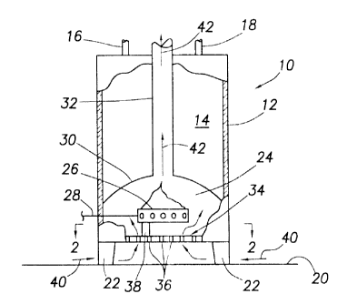
Illustrated in simplified cross-sectional form in FIG.
1 is a fuel-fired heating appliance, representatively a
gas-fired water heater 10, that embodies principles of the
present invention. Water heater 10 has a vertically
oriented cylindrical insulated metal storage tank 12 which
is adapted to hold a quantity of pressurized water 14 to be
heated and stored for on-demand delivery to a variety of
hot water-utilizing plumbing fixtures (not shown) via a
supply pipe 16 connected to the top end of the tank 12.
Water 14 drawn from the tank 12 is automatically
replenished via a cold water inlet pipe 18 also connected
to the top end of the tank 12.
The tank 12 is representatively supported on a floor
20, in an elevated relationship therewith, by depending
support legs 22. At the lower end of the tank 12 is a
combustion chamber 24 in which a schematically depicted gas
burner structure 26 is operatively supported, the burner
structure 26 being supplied with fuel gas via a supply line
28 and thermostatically controlled in a conventional manner
as a function of the setpoint temperature of the stored
water 14. Combustion chamber 24 has a domed top wall 30.
-6-
CA 02376579 2002-03-13
A flue 32 extends upwardly from a central portion of the
wall 30, through the water 14 and outwardly through the top
end of the tank 12, and communicates with the interior of
the combustion chamber 24.
A bottom outer wall portion of the combustion chamber
24 is defined by a specially designed flame arrestor plate
34 which embodies principles of the present invention and
has a spaced series of flame quenching combustion air inlet
openings 36 formed therein. The burner structure 26 is
held in an elevated relationship with the top side of the
flame arrestor plate 34 by a schematically depicted support
structure 38.
During firing of the water heater 10, ambient
combustion air 40 is flowed into the combustion chamber 24
via the air inlet openings 36, mixed with fuel gas
delivered to the burner structure 26, and combusted to form
hot combustion products 42 that upwardly traverse the flue
32 and transfer combustion heat to the water 14 through the
sidewall of the flue 32. In a manner subsequently
described herein, the arrestor plate inlet openings 36
function to permit combustion air 40 to be drawn upwardly
therethrough into the combustion chamber 24, but preclude
downward passage through the openings 36 of flames from the
interior of the combustion chamber 24. Accordingly, in the
event that extraneous flammable vapors are entrained in the
combustion air 40, drawn into the combustion chamber 24 and
ignited therein, the resulting flammable vapor flames are
kept in the combustion chamber and tend to be self-
extinguishing.
The illustrated combustion air inlet path to the flame
arrestor plate 34 has been schematically depicted in FIG.
1, and is merely representative of a variety of such paths
which could be provided for the water heater 10. As but
one example of an alternative combustion air inlet path to
the flame arrestor plate 34, a ducted path could be
-7-
CA 02376579 2002-03-13
provided to the flame arrestor plate 34 with such ducted
path having a combustion air inlet opening which is
elevated with respect to both the floor 20 and the flame
arrestor plate 34.
Turning now to FIGS. 2-6, the flame quenching
perforated arrestor plate 34 is representatively formed
from an initially imperforate, substantially planar metal
plate body 42 having upper and lower sides 44,46 and a
thickness T which is representatively in the range of from
about 0.015" to about 0.040", and is preferably about
0.026". The flame quenching openings 36 are created using
a suitable lancing process to form in the plate body 42
parallel rows of upwardly deformed elongated louvers 48,
with each of the flame quenching combustion air inlet
openings 36 being disposed between a laterally adjacent
pair of the louvers 48. Alternatively, the rows of louvers
48 could be staggered, or in other relative orientations,
instead of being parallel.
As can best be seen in FIG. 2, the plate body 42 has
a circular shape and is diametrically configured to cover
essentially the entire bottom side of the combustion
chamber 24. Representatively, a substantially larger sheet
of metal has louvers 48 lanced therein and has the circular
body 42 suitably removed therefrom. The removed circular
body 42 has the louvers crimped down around its periphery
to form an annular, imperforate peripheral area 42a which
facilitates the connection of the body 42 at the bottom of
the combustion chamber 24. Additionally, a rectangular
area 42b is crimped down to form on the top side of the
body 42 an imperforate securement area 42b on which the
burner support structure 38 (see FIG. 1) may be suitably
mounted. Alternatively, the imperforate areas 42a and 42b
could initially be formed without perforations.
While the flame arrestor plate body 42 illustratively
has a circular shape and covers essentially the entire
-8-
CA 02376579 2002-03-13
bottom end of the combustion chamber 24, it could have a
different shape and cover a lesser portion of the bottom
end of the combustion chamber 24. For example, the plate
body 42 could have a rectangular shape and be an insert in
a portion of a larger imperforate metal plate
complementarily mounted within the open bottom end of the
combustion chamber 24.
With reference now to FIGS. 4-6, each louver 48 has an
upwardly bent top plate wall segment 50 which extends along
the length of its associated flame quenching combustion air
inlet opening 36 and is upwardly slanted in a rightward or
forward direction relative to the plate body 42, and a pair
of end walls 52 which are upwardly and horizontally
inwardly sloped toward one another at an angle A (see FIG.
4) which is in the range of from about 11 degrees to about
45 degrees, and preferably about 30 degrees, relative to
the top side 44 of the plate body 42. Each forwardly and
upwardly sloped top plate wall segment 50 has an
essentially planar bottom side surface 54 that slopes
forwardly and upwardly at an angle within the range of from
about 40 degrees to about 70 degrees, and preferably about
50 degrees, relative to the top side 44 of the plate body
42, and a substantially planar front or outer end surface
56 which is upwardly and rearwardly sloped at an angle B
within the range of from about 0 degrees to about 15
degrees, and preferably about 12 degrees, relative to a
vertical reference plane 58 extending parallel to the
horizontal length of the associated combustion air inlet
opening 36 and transverse to the plane of the plate body
42.
A relatively sharp edge 60 extends along the juncture
of the surfaces 54 and 56 of each louver plate segment 50.
Edge 60 horizontally extends along the top side of the
outlet of the associated flame quenching combustion air
inlet opening 36 (see FIG. 5) and is in a parallel, spaced
-9-
CA 02376579 2002-03-13
apart and opposing relationship with an elongated,
relatively sharp edge 62 extending along the bottom side of
the outlet of the combustion air inlet opening 36 and
disposed on a front plate wall segment 64 having a
substantially planar, rearwardly facing horizontally
elongated surface 66 upwardly terminating at the edge 62.
Representatively, the minimum length L of each
combustion air intake opening 36 (see FIG. 4) is in the
range of from about 0.10" to about 0.20", and is preferably
about 0.15", and the distance S between the rows of louvers
48 is in the range of from about 0.20" to about 0.40", and
is preferably about 0.22". As shown in FIG. 5, each flame
quenching combustion air inlet opening 36 has a bottom
inlet width WI which is substantially greater than its top
outlet width Wo. Representatively, the inlet width WI is in
the range of from about 0.08" to about 0.10", and is
preferably about 0.085", and the outlet width Wo is in the
range of from about 0.015" to about 0.023", and is
preferably about 0.018". Additionally, there is a
horizontal gap G between each associated pair of outlet
edges 60,62 which has a width in the range of from about 0"
to about 0.023", and is preferably about 0.01".
According to another configurational feature of the
arrestor plate 34, at each combustion air inlet opening 36,
such as the opening 36a shown in FIG. 5, a reference
boundary X extends from the lateral midpoint of the inlet
portion of the opening to the lateral midpoint of the
outlet portion of the opening and divides the overall flow
volume of the opening into a first flow volume Vl adjacent
the upwardly bent wall segment 50 and a second flow volume
V2 equal to the flow volume Vl and positioned generally
forwardly of the volume V2 and adjacent the wall segment 64.
The interior plate surface area bounding the portion of the
opening 36a within the volume V1 is substantially greater
than the interior plate surface area bounding the portion
-10-
CA 02376579 2002-03-13
of the opening 36a - representatively from about 2 times
greater to about 8 times greater, and representatively
about five times greater.
Turning now to FIG. 6, which illustrates the flow of
combustion air 40 through a representative one of the flame
quenching combustion air inlet openings 36 in the louvered
flame arrestor plate 34, the above-described
configurational aspects of the plate 34 provide the flow of
combustion air 40 traversing each opening 46 with a unique
set of characteristics that provides the arrestor plate 34
with various operational advantages compared to
conventionally configured flame arrestor plate
constructions.
For example, the shape of each flame quenching opening
36, in addition to preventing the flow of flame downwardly
therethrough, causes combustion air 40 traversing the
opening 36 to pass therethrough in a laminar flow portion
40a disposed adjacent the planar bottom side surface 54 of
the plate segment 50, a turbulent flow portion 40b adjacent
the front plate segment 64, and a transitional flow portion
40c disposed between the flow portions 40a and 40b. As the
combustion air 40 upwardly traverses the flame quenching
opening 36 its velocity increases due to the substantial
narrowing of the opening 36 at its outlet. Additional
turbulence is imparted to the air 40 as it exits the
opening 36 due to the interaction with the air of the
facing, parallel plate edges 60,62 at the exit of the
opening 36. Combustion air 40 entering each opening 36 has
at least two directional changes imparted thereto before it
exits the opening 36.
This added turbulence imparted to the exiting air 40
creates counter-rotating vortices 40d and 40e therein at
the opening exit. The high degree of discharged air
turbulence at the exit of each of the flame quenching
combustion air inlet openings substantially prevents the
-11-
CA 02376579 2002-03-13
build-up of lint or other airborne particulate matter at
the openings 36, thereby advantageously maintaining the
free flow of combustion air 40 through the arrestor plate
34 and avoiding the necessity of frequently cleaning the
plate to unclog the openings 36. Lint or other particulate
matter which may fall toward the exit portions of the
opening 36 from within the combustion chamber 24 upon
cessation of burner operation can simply fall through the
gaps G (see FIG. 5) built into the louvered opening
configurations.
When the burner structure 26 is subsequently lit, the
resulting detonation force within the combustion chamber 24
acts to outwardly flush lint or other particulate matter
through the openings 36. Then, when combustion air 40 is
drawn into the combustion chamber 24, the resulting air
turbulence adjacent the exits of the openings 36 tends to
disperse lint or other particulates on the upper side of
the arrestor plate 34 adjacent the openings 36.
Because at each of the flame quenching openings 36 the
outlet velocity is substantially greater than the inlet
velocity, the interior combustion chamber pressure adjacent
the openings 36 is lower than the ambient pressure along
the bottom side 46 of the plate adjacent the openings 36.
This pressure differential is quite uniform over the
surface area of the arrestor plate 34. Accordingly, during
firing of the burner structure 26 the combustion air inflow
over the area of the arrestor plate 34 is also quite
uniform over the area of the bottom side of the flame
arrestor plate 34. The temperature of the plate is thus
substantially uniform over its area as is the lint
deposition pattern on the non-perforated bottom side area
of the arrestor plate 34. Further, due to this uniform
distribution of combustion air flow through the arrestor
plate 34, the operational noise attributable to the plate
is desirably diminished.
-12-
CA 02376579 2002-03-13
Moreover, compared to conventional flame arrestor
plate geometries, the above-described geometry of the
arrestor plate 34 beneficially provides for each flame
quenching plate opening 36 a very large ratio of internal
surface area to outlet area. Representatively, this ratio
is in the range of from about 120 to about 150, and is
preferably about 130. This high ratio provides the
arrestor plate 34 with improved flame quenching
capabilities, and also facilitates the above-mentioned high
degree of turbulence in the combustion air 40 upwardly
exiting the flame quenching openings 36.
The foregoing detailed description is to be clearly
understood as being given by way of illustration and
example only, the spirit and scope of the present invention
being limited solely by the appended claims.
-13-
__