Note: Descriptions are shown in the official language in which they were submitted.
CA 02376869 2001-12-11
WO 00/76410 PCT/US00/16090
CLOT EVACUATION CATHETER
FIELD OF THE INVENTION
The invention relates to clot removal devices. More particularly, the
invention
relates to catheters for evacuating clots from the bladder or thick fluids
from hollow
viscera or cavities.
BACKGROUND OF THE INVENTION
Urological procedures, such as operations and/or pathology on the bladder and
prostate, are commonly performed. A complication that may arise as a result of
such
urological procedures being performed, or as a result of diseases of the
bladder or
prostate, is the accumulation and retention of clots in the bladder or
prostate.
The presence of these clots, and the danger they potentially pose to a
patient,
have been known for decades. Many techniques and associated devices have been
employed in order to eliminate these bladder clots. Most techniques involve
the
insertion of catheters to irrigate and then evacuate the clots. For example,
one specific
technique involves the insertion of a 3-way Foley catheter to irrigate the
bladder
followed by the replacement of the Foley catheter with a Whistle tip catheter
to further
irrigate the bladder and suction away clots.
While this clot evacuation technique usually works for its intended purpose,
it is
replete with disadvantages and associated problems involving patient
discomfort,
duration, cost and risk. For example, the insertion and removal of a catheter
on two
separate occasions during one procedure increases the likelihood of triggering
acute
senses of invasiveness and discomfort in a patient. Also, when especially
large clots
are present and need to be evacuated, correspondingly large catheters must be
used,
thus necessitating the use of general anesthesia.
Another problem with this, and other techniques that employ more than one
catheter, is that certain remote but realistic risks to a patient arise upon
each insertion
of a catheter (i.e., bladder injury or rupture, bacteremia) and accompany any
usage of
general anesthesia (i.e., allergic reaction by the patient, overdose).
Furthermore, these
prior art clot evacuation techniques are costly due to the surgical time
required and the
use of general anesthesia.
-1-
CA 02376869 2001-12-11
WO 00/76410 PCT/US00/16090
Another technique for eliminating clots in the bladder or prostate is to cut
the
clots with a catheter equipped with cutting blades. Catheters equipped with
cutting
blades, however, have yet to adequately reconcile safety issues with
performance
issues. For example, large and powerful blades are required to cut large
bladder clots;
however, such catheters do not adequately protect the bladder wall from being
cut while
the blade is active.
Various clot evacuation catheters are shown and described in U.S. Patent Nos.
4,020,847 (to Clark, III); 4,631,052 (to Kensey); 4,754,755 (to Husted);
4,790,812 (to
Hawkins, Jr. et al.); 5,520,635 (to Gelbfish) and 5,643,296 (to Hundertmark).
A need remains, however, for a catheter which will enable the effective
removal
of clots of varying size from the bladder and/or prostate while minimizing the
cost and
duration of the process, and the discomfort and risk of harm to the patient
during the
process.
SUMMARY OF THE INVENTION
The present invention provides a clot evacuation catheter. Although the
invention is primarily shown and described as a device to cut and evacuate
clots from
the bladder, it is understood that the device has other applications as well.
The clot evacuation catheter includes a tubular body disposed within an outer
lumen. The outer lumen and tubular body are concentric and have coaxial
longitudinal
axes. The outer lumen has an open distal end, and the tubular body has a
distal portion
with an opening therein.
The tubular body is elongate and hollow and has a cutting blade disposed
within
the distal portion thereof to cut clots. The cutting blade is substantially
disk-shaped and
is selectively rotatable in a plane transverse to the longitudinal axis of the
tubular body.
The cutting blade has at least one opening within which clots occlude and are
cut. The
cutting blade is mounted to a wall of the tubular body such that the tubular
body and the
cutting blade are selectively rotatable with each other. The catheter also
includes a
fluid conveying irrigation lumen. The irrigation lumen extends longitudinally
through
the catheter and has an open distal end disposed proximal to the cutting
blade.
In another embodiment, the catheter further includes a hood member that is
formed on and extends distally from the distal portion of the tubular body. A
dome-like
-2-
CA 02376869 2001-12-11
WO 00/76410 PCT/US00/16090
distal end of the hood member shrouds the distal portion of the tubular body
while
allowing access to the tubular body through a side opening in the hood member.
BRIEF DESCRIPTION OF THE DRAWINGS
A more complete understanding of the present invention and the attendant
advantages and features thereof will be more readily understood by reference
to the
following detailed description when it is considered in conjunction with the
accompanying drawings, wherein:
FIG. 1 is a front view, with partial cut-away, of an embodiment of the clot
evacuation catheter of the present invention;
FIG. 2 is a cross-sectional view of the clot evacuation catheter of FIG. 1
taken
along the line 2-2;
FIG. 3 is a perspective view of a cutting blade of the clot evacuation
catheter of
FIG. 1;
FIG. 4 is a front view, with partial cut away, of the clot evacuation catheter
of
FIG. 1 inserted within a Foley catheter; and
FIG. 5 is a schematic illustration of the operation of a clot evacuation
catheter
according to the present invention.
DETAILED DESCRIPTION OF THE INVENTION
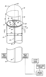
A clot evacuation catheter 10 in accordance with the present invention is
depicted in FIG. 1. The catheter 10 has a tubular body 12 through which clots,
such as
bladder clots, may be evacuated after being cut by a cutting blade 14. The
tubular body
12 of the catheter 10 is elongate, hollow and substantially cylindrical, with
a proximal
end 18 and an open distal portion 20. The tubular body 12 is disposed within
an outer
lumen 22 that has an open distal end 24. The tubular body 12 and the outer
lumen 22
are generally concentric, and have longitudinal axes that are coaxial with a
longitudinal
axis 26 of the catheter 10.
The outer lumen 22 and the tubular body 12 are each substantially cylindrical.
The outer lumen 22 has a longitudinal length greater than the length of the
tubular body
12 and a diameter 30 that is substantially constant and greater than the
substantially
-3-
CA 02376869 2001-12-11
WO 00/76410 PCT/US00/16090
constant diameter 32 of the tubular body. Whereas the tubular body 12 and the
outer
lumen 22 each may be adapted to rotate, the outer lumen 22 is preferably
static.
The catheter 10 also includes a fluid conveying irrigation lumen 34 to deliver
an
irrigating fluid to a distal end 35 of the catheter 10 at predetermined times
in order to
soften clots. The irrigation lumen 34 is disposed within, and extends
longitudinally
through the tubular body 12 of the catheter 10 and is preferably static. The
longitudinal
length of the irrigation lumen 34 is generally less than either the length of
the outer
lumen 22 or the length of the tubular body 12. The irrigation lumen 34 has an
open
distal end 36 that is proximal to the cutting blade 14 of the catheter 10.
The irrigation lumen 34 is substantially cylindrical and has a substantially
constant diameter 38. In an exemplary embodiment, the irrigation lumen 34 is
contained within the outer wall 40 of the tubular body 12 and is proximal to
the cutting
blade 14 of catheter 10. Preferably, and as shown in FIG. 2, the irrigation
lumen 34
contacts both walls 40, 42 such that the diameter 38 of the irrigation lumen
is
approximately equal to the difference between the diameter of the outer lumen
22 and
the diameter of the tubular body 12. Alternatively, the irrigation lumen may
be
disposed within the tubular body 12 and/or may be positioned such that it does
not
contact either wall 40, 42.
The irrigation lumen 34 is adapted to provide controlled delivery of
irrigating
fluid to the distal end 35 of the catheter at predetermined times. In an
exemplary
embodiment, irrigating fluid is delivered when one or more clots occlude at
least one
opening 44 in the cutting blade 14. The fluid softens the clots) and
facilitates the
cutting thereof by at least one cutting member 48 of the cutting blade 14. One
of
ordinary skill in the art will readily appreciate that the timing of fluid
delivery and the
volume of fluid delivered may be varied depending upon the need of a given
procedure.
An exemplary irrigating fluid is saline, but one of ordinary skill in the art
will also
appreciate that other sterile fluids may be used as irrigation fluids.
The catheter 10 may also include a hood member 16 that extends from the distal
portion 20 of the tubular body 12. In an exemplary embodiment, the hood member
16
has a closed, dome-like distal end 28 that is mounted to the tubular body 12
by a side
portion 19. A side-facing space or opening 17 separates the dome-like distal
end 28 of
the hood member 16 from the distal portion 20 of the tubular body 12. The hood
-4-
CA 02376869 2001-12-11
WO 00/76410 PCT/US00/16090
member 16 is useful to shroud the distal end 35 of the catheter, thereby
preventing the
cutting blade 14 from inadvertently damaging healthy tissue.
The hood member 16 preferably has a diameter greater than or approximately
equal to the diameter 30 of the outer lumen 22. The side-facing opening 17 of
the hood
member 16 should have dimensions that are suitable to allow clots to enter the
hood
member and contact cutting blade 14. One of ordinary skill in the art can
readily
determine the dimensions of this opening. Generally, however, the opening has
a
height (H) of about 2.0 millimeters to 7.0 millimeters.
A cutting blade 14 useful with the present invention is shown in FIG. 1 and,
in
particular, FIG. 3. The cutting blade 14 should be shaped and oriented so as
to be able
to rotate and cut any clots that are to be evacuated. The cutting blade 14 is
disposed
within the distal portion 20 of the tubular body 12 of a catheter 10 and is
selectively
rotatable in a plane transverse to the longitudinal axis 26 of the tubular
body.
In an exemplary embodiment, the cutting blade 14 is in the form of a disk-like
member with an outer rim 46 and at least one opening 44 formed in the cutting
blade
14. In the embodiment depicted in FIGS. 1 and 3, the cutting blade 14 has two
openings 44, each of which are wedge-shaped. The location of these openings 44
results in the formation in the cutting blade 14 of two wedge-shaped cutting
members
48. The edge 51 of each wedge-shaped cutting member 48 adjacent to openings 44
serves as a leading edge which, upon rotation of the cutting blade 14, is
effective to cut
a clot to a size small enough to enable the clot to pass through openings 44
to be
evacuated through catheter 10. Although the openings 44 are described and
illustrated
as wedge-shaped, they may assume a variety of other shapes as well. Also, the
number
of openings 44 may be greater or less than two.
The dimensions of the cutting blade 14 may vary depending upon the
requirements of a given application. In one embodiment, the cutting blade 14
has a
diameter in the range of about 2.0 millimeters to 10.0 millimeters and a
thickness of
about 0.5 millimeter to 2.0 millimeters. Where two openings 44 are used, the
total
surface area of the cutting blade 14 occupied by the openings 44 is in the
range of about
0.785 mm2 to 30.00 mm2, or about 50 to 75 percent of the surface area of the
cutting
blade. Also, the cutting blade 14 is generally disposed proximal to the distal
end 24 of
the tubular body 12 by a distance between about 0.1 millimeter and 1.0
millimeter.
-5-
CA 02376869 2001-12-11
WO 00/76410 PCT/US00/16090
The cutting blade 14 can be made from a variety of materials such as polymers,
ceramics, metals and metal alloys. In one example, the cutting blade 14 is
made from a
polymer and is coated with polytetrafluoroethylene.
As noted above, the cutting blade 14 is rotated to effect cutting of clots.
The
catheter 10 may be designed so that the cutting blade 14 is rotatable with, or
independent of the tubular body 12. In one embodiment, the cutting blade 14
may be
mounted to an inner wall 40 of the tubular body 12, as shown in FIG. 1, such
that the
cutting blade and the tubular body are selectively rotatable with each other.
The cutting
blade 14 is adapted to rotate when the size or weight of clots) that occlude
the at least
one opening 44 of the cutting blade create a predetermined level of vacuum
force as
detected by a vacuum force sensor.
In the embodiment depicted in FIG. 1, in which the cutting blade 14 and the
tubular body 12 rotate together, the proximal end 18 of the tubular body is in
communication with a motive force provider that rotates the tubular body and
cutting
blade when a predetermined level of vacuum force (e.g., above about 30 cm H20)
is
detected by a vacuum force sensor. The vacuum force sensor is in communication
with
a control element. When a predetermined level of vacuum force is detected by
the
vacuum force sensor, the control element sends a signal to the motive force
provider
and to a vacuum source. The motive force provider then rotates the tubular
body 12
and cutting blade to cut clots that occlude openings 44 in cutting blade 14.
At the same
time, the vacuum source applies a force in the magnitude of about 40 cm H20 to
200
cm HZO to assist in the evacuation of clots through the catheter 10.
The cutting blade 14 may alternatively be mounted within a groove, track or
rail
(not shown) formed within an inner wall of the tubular body 12. In such an
embodiment, the groove should be of sufficient diameter and longitudinal
length to
allow the cutting blade to be placed, and to rotate, therein.
Referring now to FIG. 4, an alternate embodiment of the clot evacuation
catheter 10 is shown disposed in a Foley catheter 100. The clot evacuation
catheter 10
of FIG. 6 is substantially identical to the embodiment illustrated in FIG. 1,
except that
it does not include a hood member 16. The hood member 16 is generally not
required
in this embodiment because its function of guarding areas of the body from the
cutting
-6-
CA 02376869 2001-12-11
WO 00/76410 PCT/LJS00/16090
blade 14 is accomplished by the clot evacuation catheter 10 being disposed
within the
Foley catheter 100.
The Foley catheter 100 is of a type well known in the art and includes a
distal
portion 104, a proximal portion 106 and at least one opening 108 through which
clots
may pass. The Foley catheter 100 may also include an irrigation lumen (not
shown),
and/or other features generally known in the art to ensure, and facilitate,
the entry of
clots within the Foley catheter 100 and the clot evacuation catheter 10.
The catheter 10 may be disposed within the Foley catheter 100 in one of
several
ways generally known in the art. In the exemplary embodiment of FIG. 4, an
adapter
101 is disposed around the catheter 10 and against the Foley catheter 100 with
sufficient
tightness to maintain the position of the catheter with respect to the Foley
catheter. The
position of the catheter 10 with respect to the Foley catheter 100 may be
changed by
loosening a nut or other tightening means 103, changing the position of the
catheter,
and then tightening the nut or tightening means.
In an exemplary embodiment, the Foley catheter 100 shares the longitudinal
axis
26 of the catheter 10 and is surrounded by a balloon 102. The balloon 102 is
effective
to maintain the position of the Foley catheter 100 inside the bladder or other
body area
in which the Foley catheter is placed. The openings 108 of the Foley catheter
100
generally have identical dimensions and are located between the distal and
proximal
portions 104, 106 of the Foley catheter. The distal end 35 of the clot
evacuation
catheter 10 preferably is transversely aligned with the openings 108 of the
Foley
catheter 100 to increase the likelihood that clots which enter the Foley
catheter will
subsequently enter the tubular body and be cut by the cutting blade 14. The
cutting
blade 14 to be used with the embodiment shown in FIG. 4 may rotate with, or
independent of, the tubular body 12.
The dimensions of the clot evacuation catheter 10 and its components may vary
based on the dimensions of the Foley catheter 100 in which it is disposed.
Generally,
however, the diameter 30 of the outer lumen 22 of the clot evacuation catheter
10 will
be between about 0.1 millimeter to 1.0 millimeter less than the diameter 110
of the
Foley catheter 100.
Referring now to FIG. 5, the clot evacuation catheter 10 of FIG. 1 is shown
disposed in the bladder 120 or other body area. The catheter 10 may enter and
be
CA 02376869 2001-12-11
WO 00/76410 PCT/US00/16090
maneuvered through the bladder 120 as is generally known in the art in order
to be able
to evacuate any clots 122 present in the bladder. Although the catheter 10
shown in
FIG. 7 is of the type depicted in FIG. 1, an embodiment of the type depicted
in FIG. 4
may alternatively be used.
The catheter 10 may be placed into the bladder 120 or other body area to
specifically cut clots 122 that are known to be present therein.
Alternatively, the
catheter 10 may be placed into the bladder 120 or other body area in
anticipation of the
appearance of clots 122. For example, the catheter 10 may be placed into the
bladder
120 either before, during or immediately following bladder pathology or
surgery. Cut
clots 124 are forced proximal to the cutting blade 14 and through the tubular
body 12 of
the catheter 10 and are collected as is generally known in the art.
In an exemplary embodiment, the catheter 10 of FIGS. 1, 4, or 5 may have
certain dimensions. For example, the tubular body 12 may have a longitudinal
length
28 between about 200 millimeters to 500 millimeters, and a diameter 32 between
about
2.9 millimeters to 9.9 millimeters. Further, the outer lumen 22 may have a
longitudinal length between about 200 millimeters to 500 millimeters, and a
diameter
30 of between about 3.0 millimeters to 10.0 millimeters. The irrigation lumen
34 may
have a diameter 38 and a longitudinal length that are, respectively, between
about 0.5
millimeter to 2.0 millimeters and about 200 millimeters to 500 millimeters.
The hood
member 16, when included, may have a distal end 17 diameter between about 4.0
millimeters to 9.0 millimeters.
The present invention also contemplates embodiments of the catheters 10 of
FIGS. 1, 4, or 5 in which a tubular body 12 is not disposed within an outer
lumen 22.
In such embodiments, the tubular body 12 would have a similar diameter 30 to
the
embodiments of FIGS. 1, 4 and 5, but also would also have a thicker outer wall
that
houses a port or channel. The port or channel would be adapted to provide air
compression or liquid force to rotate the cutting blade 14 of the catheter 10.
The
catheter 10 would otherwise be substantially similar in its components,
dimensions and
operation to either of the catheters described with respect to FIGS. 1, 4, and
5.
Further, the catheter 10 of the present invention may optionally include a
balloon or other device for maintaining the catheter in an indwelling position
within a
body cavity without requiring the use of a Foley catheter as shown in FIGS. 4
and 5.
_g_
CA 02376869 2001-12-11
WO 00/76410 PCT/LTS00/16090
Although the invention has been shown and described with respect to exemplary
embodiments thereof, various other changes, omissions and additions in form
and detail
thereof may be made therein without departing from the spirit and scope of the
invention. All references and publications cited herein are expressly
incorporated
herein by reference in their entirety.
What is claimed is:
-9-