Note: Descriptions are shown in the official language in which they were submitted.
CA 02376983 2001-12-14
WO 00/77990 PCT/LJS00/16390
Client/Server Based Architecture for a Telecommunication Network
Technical Field of the Invention
The present invention relates generally to the field of
telecommunications and, in particular, to a client/server based architecture
for a telecommunications network.
Background
The rise in the popularity of new forms of communication such as the
Internet has driven the need for network systems that offer greater and
greater amounts of bandwidth. Prior to the explosion of the Internet's
popularity, most telecommunications systems were designed with an
architecture to support primarily a single service (e.g., voice calls). Today,
the newer telecommunication systems must be designed for the larger
bandwidth demands of data traffic.
Current networks provide a communication stream of traffic between
a user and a content provider, the two edges of a communication link.
Essentially, all media traffic (e.g., Internet protocol (1P) traffic) with the
signaling and service attributes flow in the same channel of the network;
fitting into the "in-band" control paradigm. This communication link typically
includes an access network that provides access for users to a core
transport network. Typically, the core network and the access network do
not have the intelligence to streamline control information and to act upon
it.
It is simply not cost effective for these networks to be continuously
upgraded to support new control information models (e.g., models that are
designed at layer 3 or higher in the protocol stack) as they are developed.
Thus, today, the core and access networks are relatively inflexible networks
that provide simple bandwidth pipes from end users to the content providers.
One example of a current architecture for higher bandwidth
applications is the digital subscriber line (DSL), a technology that
dramatically increases the digital capacity of ordinary telephone lines (the
CA 02376983 2001-12-14
WO 00/77990 PCT/US00/16390
2
local loops) into the home or office. At the central office (CO), a device
known as the digital subscriber line access multiplexer (DSLAM) for DSL
service intermixes voice traffic and data traffic onto a customer's DSL line.
It
also separates incoming phone and data signals and directs them onto the
appropriate carrier's network. A DSLAM is a transport device that typically
deploys bandwidth services ranging from 1.5 to 6 Mbps downstream and
250 Mbps to 512 Mbps upstream.
One problem with a DSLAM is that the DSLAM performs a relatively
non-intelligent transport function. In essence, the DSLAM takes in tower
speed data lines and multiplexes the data lines into a higher speed link. The
DSLAM does not manage or switch data because, by its very definition, the
DSLAM performs a multiplexing function and does not understand the
services that are being transported in the data stream. In addition, no time
domain gains are achieved, as DSLAMs just multiplex data and do not
perform call setup and switching on demand. The DSLAM design limits the
ability of the system to deliver only a limited amount of bandwidth to the end
customer. Through buffering techniques bandwidth can be oversubscribed,
but due to the limitations of the DSLAM, the service provider cannot tear
down and set up calls to deliver just the right amount of bandwidth in a
certain time domain. To overcome this problem, additional equipment must
be used in conjunction with a DSLAM that know about the services to assist
in improving allocation of resources.
For example, a DSLAM can be used to provide Internet access by
providing a point-to-point protocol (PPP) server on the network side of the
DSLAM. Basically, the PPP server is an additional module that makes an
association between a user and a connection for a particular Internet service
provider (ISP) that the user wants to connect to, so that the user can get
onto the Internet. Unfortunately, this PPP server only addresses the
problem controlling a single service. Subscribers may desire additional
services over their ADSL line. With a typical ADSL line, a subscriber
receives one regular phone line and a data connection. Oftentimes, a user
will want more phone lines or other services in addition to Internet access.
CA 02376983 2001-12-14
WO 00/77990 PCTNS00/16390
3
To accomplish this, the service provider must add other equipment semi-in
parallel to supplement the DSLAM and/or change the end devices to
provide, e.g., voice over ATM, because a DSLAM has no service level
knowledge of the data that is passing through it. Essentially, additional
equipment or modules must be added at the central office for every different
service provided to a subscriber.
Another problem with a network architecture based on the DSLAM is
the delivery of higher bandwidth services. Because the DSLAM is designed
for primarily to perform a transport multiplexing function, a conventional
DSLAM is not flexible in assigning additional network side trunk resources.
Thus to address higher bandwidth services, e.g., for video on demand, the
service provider may install yet another system in parallel with the DSLAM to
provide access to this service.
For the reasons stated above, and for other reasons stated below
which will become apparent to those skilled in the art upon reading and
understanding the present specification, there is a need in the art for an
improved architecture for a telecommunications network.
Summary
The above-mentioned problems with telecommunications networks
and other problems are addressed by the present invention and will be
understood by reading and studying the following specification. A
telecommunications network is described which employs a client/server
architecture to allow intelligent allocation of bandwidth at a multimedia
channel bank. The multimedia channel bank acting as a client is controlled
by signals from a multimedia resource manager that acts as a server.
The client/server architecture provides a new way to streamline
services and respond to new services layered on top of various
transmission/transport access networks. By separating the transport entity
(e.g., the multimedia channel bank or client) and the entity controlling Layer
3+ intelligence (e.g., the multimedia resource manager or server) required to
CA 02376983 2001-12-14
WO 00/77990 PCT/US00/16390
4
respond to service requests, the client/server architecture provides the
following advantages:
1. The multimedia channel bank provides a transport oriented
element (e.g., high capacity transport on layers 1-3 of the protocol stack)
that is capable of implementing intelligent functionality provided by the
server while being embodied in hardware that can be located in an outside
plant environment.
2. The multimedia resource manager provides layer 3 and above
intelligence to the multimedia channel banks and accommodates software
stacks and APIs. This is the suitable platform to provide intelligence while
keeping an open environment for new enhancements.
3. As a server, the multimedia resource manager provides a
mechanism for the multimedia channel banks to communicate with layer 3
and higher servers (e.g., content providers, Internet service providers
(ISPs)).
4. The multimedia resource manager, as a server, can use
commercial database information models to tailor specific service/user
profiles.
As a further advantage, the client/server architecture allows the
access network to respond to "out of band" control information and user
requests on a dedicated, specialized server platform. This server (e.g., the
multimedia resource manager) allows the network to handle multiplicity of
protocols, APIs stacks and has the visibility to massive databases of service
attributes, end-user profiles and accounts. The client/server architecture
further provides the intelligence required to offer differentiated services on
top of the ATM/IP transport network.
Brief Description of the Drawings
Figure 1 is a diagram that illustrates an embodiment of a client/server
based telecommunications network according to the teachings of the
present invention.
CA 02376983 2001-12-14
WO 00/77990 PCT/US00/16390
Figure 2 is a block diagram of an alternative embodiment of a
telecommunications network according to the teachings of the present
invention.
Figure 3 is a block diagram of an alternative embodiment of a
5 telecommunications network according to the teachings of the present
invention.
Figure 4 is a block diagram of an alternative embodiment of a
telecommunications network according to the teachings of the present
invention.
Detailed Description
The following detailed description refers to the accompanying
drawings that form a part of the specification. The drawings show, and the
detailed description describes, by way of illustration specific illustrative
embodiments in which the invention may be practiced. These embodiments
are described in sufficient detail to enable those skilled in the art to
practice
the invention. Other embodiments may be used and logical, mechanical
and electrical changes may be made without departing from the scope of the
present invention. The following detailed description is, therefore, not to be
taken in a limiting sense.
Figure 1 is a block diagram that illustrates a telecommunications
network 100 according to the teachings of the present invention.
Telecommunications network 100 uses a client/server architecture to
provide access to networks that carry a variety of data, e.g., voice, video,
and data. Advantageously, the use a client/server architecture allows
intelligent allocation of bandwidth and control of a variety of services to be
supported without the need to add additional equipment to the system as
services are added or modified. Thus, telecommunications network 100 can
be termed a "multimedia" network that provides intelligent allocation of
bandwidth to carry voice, data, and video signals between users and the
network. In Figure 1, telecommunications network 100 is illustrated as
providing access to at least three different types of networks. These include
CA 02376983 2001-12-14
WO 00/77990 PCT/US00/16390
6
a time division multiplex (TDM) network for voice communications services
101 (e.g., the public switched telephone network (PSTN)), a cell/packet
network for digital data information 102 (e.g., an asynchronous transfer
mode (ATM) network), and a signaling/application protocol interface (API)
network 103.
The telecommunications network 100 includes a plurality of
multimedia channel banks (MCBs) 104-1, . . ., 104-N which replaces the
traditional remote terminal (RT) of a digital loop carrier (DLC) system and
potentially remote DSLAMs and ONUs. Each of the MCBs 104-1, . . ., 104-
N include a number of port cards, 105-1, . . ., 105-M. MCBs 104-1, . . ., 104-
N provide an edge access platform that supports narrowband and
broadband traffic flows. In one embodiment, the port cards 105-1, . . ., 105-
M include plain old telephone service (POTS) cards with 24 channels per
card, integrated services digital network (ISDN) port cards with 12 channels
per card, and asynchronous digital subscriber line (ADSL) port cards with six
channels per card. Each of the port cards, 105-1, . . ., 105-M couple to
numerous types of user equipment, 106-1, . . ., 106-K. The user equipment
106-1,...106-K, includes, for example, telephones, computers, video set-top
boxes, and other multi-media devices that produce data and video signals.
As part of the MCBs 104-1, . . . , 104-N, the port cards, 105-1,...,
105-M couple to a flow engine 107 that is modifiable via signals from a
traffic-servicing client 120. The flow engine 107 assigns and manages the
ATM/IP flows for the transmission of data signals to and from the user
equipment 106-1,..., 106-K. In other words, the flow engine 107 has an
ATM/IP layer visibility. The flow engine 107 grooms and multiplexes
services for transmission over a high-speed link 109-1, . . ., 109-N. In one
embodiment, the high-speed links 109-1, . . ., 109-N are OC-3c/OC-12c
lines according to the synchronous optical network (SONET) standard, to a
packet/cell based core network.
As shown in Figure 1, the ATM/IP flows from MCB 104-1 to 104-N are
transported by a generic cell/packet network102. Network 102 provides
connectivity and on-demand assignment of ATM/IP flows (e.g., private
CA 02376983 2001-12-14
WO 00/77990 PCT/US00/16390
7
network to network interface (PNNI), LDP) to the content providers. The
network 102 provides the connectivity between the MRM 112, which is the
Server, to a voice over gateway (VOG) 114 and multiple MCBs, 104-1, . . .,
104-N, acting as clients.
The VOG 114 has a similar functionality to a TDM gateway. In one
embodiment, the VOG 114 terminates one OC-12c link from the network
102. The OC-12c provides DS1 CES traffic. The DS1s carry DSO voice
channels from the MCBs 104-1, . . ., 104-N. In one embodiment, the VOG
114 mediates these DS1s to a Class 5 TR-008 or GR-303 interface to the
PSTN 101. The VOG 114 is capable of processing 2016 DSO channels for
GR-303 or TR-008 interfaces. With a 1:4 internal concentration in VOG
114, the fan-out is 8064 DSO channels.
In one embodiment, the VOG 114 supports signaling system 7 (SS7)
signaling. In this example, the DSO assignment of the VOG 114 is
controlled by the MRM 112. VOG 114 provides tones and collects dual tone
multi-frequency (DTMF) digits. With SS7 implementation, the VOG 114
supports channelized high capacity links (e.g. DS3, OC-3). Several VOGs
114 may be stacked to provide a single SS7 termination point.
The Multimedia Resource Manager (MRM) 112 serves as a real time
signaling proxy and resource manager capable of controlling traffic attributes
and user profiles of multiple MCBs 104-1, . . ., 104-N and VOGs 114. These
attributes include, but are not limited to, routing information, protocols for
service connection, Class of Service, and other appropriate attributes of a
telecommunications connection. The MRM 112 controls the attributes of
MCB 104-1, . . ., 104-N and VOG 114 in response to several triggers, e.g.
scripts, network signaling, end-user signaling, and APIs. To accomplish this,
the MRM 112 includes a server that is communicatively coupled to, for
example, client 120 of MCB 104-N. The MRM 112 can be located almost
anywhere in the network 100, with established communication links with
clients at the MCBs 104-1, . . . , 104-N and VOGs 114. In one embodiment,
the MRM 112 controls on-demand adaptation profiles of IP traffic flows to
CA 02376983 2001-12-14
WO 00/77990 PCT/US00/16390
8
ATM virtual circuits (VCs) and acts as a server to user equipment 106-1, . .
.,
106-N, e.g., a VDSL set-top box.
In one embodiment, the MRM 112 is implemented as a software
platform on a standard UNIX/NT platform. The MRM 112 acts as a layer 3
(and above) server to MCBs 104-1, . . ., 104-N. For example, the MRM
communicates with end user applications, e.g., SVC (Win2000), web
browser plug-ins, based on layer 3 or higher information exchange. The
MRM 112 also controls the attributes and resources of the MCBs 104-1, . . .,
104-N in response to multiple triggers to provide streaming of a variety of
services to user equipment 106-1, . . ., 106-K. In one embodiment, the
MRM 112 responds to the following triggers:
1. The end-user signaling/request for services. These requests
can be generated by ADSL ATU-R, VDSL set-top box, HomePNA NID, WEB
browser or any other intelligent terminal or software package at user
equipment 106-1, . . ., 106-K. The messages are tunneled to the MRM 112
by the MCB 104-1, . . . , 104-N. The MCB 104-1, . . . , 104-N may need to
provide low-layer message processing so as not to overload the MRM 112
real-time and communication link, e.g., Layer 2 termination. The MRM 112
modifies the profile of these elements in response to a service request.
2. External signaling/service request. These requests can be
generate by content providers/servers, outband signaling network, e.g. SS7,
or proprietary implementations. These requests may communicate directly
to the MRM 112 from the ISP/content provider/Service Farm and associate
the requested service with a specific end-user associated with the MRM
112.
3. Network signaling, tunneled by the MCB, e.g. Q.2931.
In one embodiment, the MRM (112) has a secure and protected high-
speed communication channel to the MCBs 104-1, . . . , 104-N, (e.g., IP
tunnels). This communication channel may comprise a permanent virtual
circuit (PVC). This communication channel allows MCBs 104-1, . . ., 104-N
to set up/tear down ATM virtual circuits (VCs) with an allocated profile from
MRM 112 in response to multiple triggers. This channel is also used to
CA 02376983 2001-12-14
WO 00/77990 PCT/US00/16390
9
modify the profile of established broadband connections, e.g. PVCs. In the
time division multiplexed (TDM) domain, the MRM 112 also supports SS7
and GR-303. After receiving a trigger, the MRM 112 may need to consult
internal or external data-base 122 for certain attributes and initiate
resource
allocation commands to a certain MCB104-1, . . ., 104-N, for a certain user
equipment 106-1, . . ., 106-K. Optionally, the MRM 112 may propagate the
service request to a content provider.
The management and provisioning of the MCBs 104-1, . . ., 104-N
and the VOG 114 may be implemented by the MRM 112. As an option, the
management application may reside on a different host (physically detached
from the MRM). In one embodiment, the MCBs 104-1, . . ., 104-N are
associated with the MRM 112 and are associated with a management
application, on a different Server.
In one embodiment, the MRM 112 is a redundant platform that
resides in, e.g., at least two locations.
Embodiments using the Client/Server Based Architecture
Figure 2 is a block diagram of another embodiment of a
telecommunications network indicated generally at 200. Network 200
presents how a client/server-based architecture provides distributed
broadband call agents. In this embodiment, the user requests a broadband
service that translates to a new broadband traffic flow through the network,
up to the content provider 210. In this embodiment, the MCB 220 sets the
traffic flow (managing the layer 1 through 3 attributes), while the MRM 230
provides the intelligence to establish the broadband flow. In this
embodiment, the service flow goes as follows. First, the user receives a
complete profile as to how to launch the service, e.g. accessing a home
page of a content provider 210. The information may include security keys,
traffic attributes, address information, and other information that is used to
communicate with content provider 210. Second, the user uses a certain
application socket to activate a protocol stack towards the network, e.g.,
MCB 220. The call/service initiation message is intercepted by the MCB 220
and tunneled to the MRM 230.
CA 02376983 2001-12-14
WO 00/77990 PCT/US00/16390
Third, the MRM 230 analyzes the message content and acts upon it.
This includes, but is not limited to: resolving the destination addresses and
making the routing choice, consulting a database for security, and
authorization, translating the request to the required network protocol stack,
5 and generating reports to a billing server. Fourth, the MRM 230 completes
the processing. To complete the processing the MRM launches the
applicable protocol stack in the MCB 220 and modifies the MCB 220
resources to correspond to the new request. Upon completion, the network
200 and the user side connections are formed and the broadband traffic flow
10 is assured.
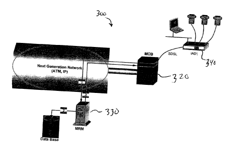
Figure 3 is a block diagram that illustrates another embodiment of a
telecommunications network indicated at 300 that manages Internet protocol
(1P) traffic flow. In this embodiment, the MCB 320 hands-off native IP drops,
which terminate in an integrated access device (IAD), or a customer
premises equipment (CPE) 340. IAD/CPE may represent, for example, a
hub for home networks, set-top boxes or any other broadband termination
point. In the architecture of network 300, the MCB 320 processes the traffic
in layer 2 or 3, while the MRM 330 provides the intelligence of how to route
the traffic, classify it, apply policing/quality of service (QoS), etc, to
individual
flows. A module on the MCB 320 terminates the physical drop, e.g. a
synchronous digital subscriber line (SDSL) and maps the IP flow in to the
ATM VC. The IP processing, mapping profile and the policing profile are
dynamically enabled by the MRM 330, upon triggers from the MCB 320. In
one embodiment, the MRM 330 provides the intelligence for the IAD, e.g.
call agent.
In this embodiment, the IP module in the MCB 320, houses IP
processing, e.g. routing, Multi Protocol Label Switching (MPLS). The IP
module itself uses the MCB 320 common as an ATM fabric and
communicates indirectly with the MRM 330. The MRM 330 provides a
gateway element for CPE management (IAD/CPE uses the MRM 330 for
proxy to separate application for configuration, alarms, etc.).
CA 02376983 2001-12-14
WO 00/77990 PCT/US00/16390
11
Figure 4 is a block diagram of another embodiment of a
telecommunications network indicated generally at 400 and constructed
according to the teachings of the present invention. In this embodiment,
network 400 finds application as the next generation of a digital loop carrier
(NGDLC). The NGDLC application utilizes the distributed architecture of
network 400 to serve large numbers of physically dispersed telephony users,
using a common ATM transport and minimizing the Class 5 (or other TDM
element) resources. The VOG 450 is the TDM Point of Presence, providing
any TDM network interface. The MRM 430 works with the VOG 450 to
resolve the TDM signaling.
The MCBs 420-1, . . ., 420-L will be populated with large number of
telephony ports (which coexist with other broadband ports). All telephony
users are being multiplexed and concentrated (based on configurable 1:N
ratio) at the MCBs 420-1, . . ., 420-L and all traffic is backhauled to the
VOG
450, as DS1 CES traffic (via the packet network).
In this embodiment, the VOG 450 terminates traffic for multiple MCBs
420-1, . . ., 420-L and streamlines all DSO traffic to TR-008 and GR-303
interfaces. The VOG 450 can provide the channelized, high capacity
interfaces (DS-3, OC-3) for Next Generation Switches, which are positioned
to displace Class 4 and 5 TDM switches. The VOG 450 is a flexible, high-
capacity TDM hub, which can handle up to 2016 simultaneous DSO calls.
Any telephony user can be associated with any interface group (TR-008,
GR-303).
In one embodiment, the VOG 450 provides SS7 peer-to-peer
connectivity to the Next Generation Switches. The MRM 430 provide the
SS7 processing while managing the DSO and internal resources of the VOG
(digits collection, etc.).
Considering a FTTS area deployment, each MCB supports 300-500
users. Assuming a one to two concentration ratio, each VOG 450 supports
6-13 MCBs. With higher a concentration ratio, 1:4 (typically exercised for
residential users), each VOG 450 can support 12-26 MCBs.
CA 02376983 2001-12-14
WO 00/77990 PCT/US00/16390
12
The MRM 430 brings more value in this application. For example,
configuring MCBs 420-1, . . ., 420-L with high DSO concentration ratios.
MRM 430 will track DSO activity and when peak demand is detected in a
certain MCB 420-1, . . ., 420-L, MRM 430 establishes an additional switched
virtual circuit (SVC), between the MCBs 420-1, . . ., 420-L and VOG 450,
with more bandwidth for voice traffic.
Conclusion
Although specific embodiments have been illustrated and described
herein, it will be appreciated by those of ordinary skill in the art that any
arrangement which is calculated to achieve the same purpose may be
substituted for the specific embodiment shown. This application is intended
to cover any adaptations or variations of the present invention. For
example, the MCBs 104-1, . . ., 104-N can be modified by appropriate port
cards to provide multimedia services other than those specified above.
Further, the term "packet network" is intended to cover any appropriate
packet or cell based network including, but not limited to, an asynchronous
transfer mode network.