Note: Descriptions are shown in the official language in which they were submitted.
CA 02377042 2002-O1-28
WO 01/06944 PCT/EP00/07024
1
A DEVICE FOR DENTAL IMPLANTATION
Field of the invention
The invention consists of a device for dental implantation (hereafter referred
to as:
"the implant") meant to replace the root of a lost tooth and help the
maintenance
s and/or reconstruction of the peridental tissues (bone and gum); the final
surface
edge of its neck has a profile which basically corresponds to that of the
margin of
the alveolar bone crest in a state of parodontal health.
Background of the invention
The implants are well known in the previous technique and widely used to
replace
io the roots of lost teeth.
For such purposes, the implants are inserted into the maxillary or mandibular
bone
in place of the missing roots and are afterwards connected thereto with an
additional structure (the so-called "prosthetic stump") on which the
artificial tooth
crown or another type of support for dental prosthesis is secured.
is The implants are usually made of titanium or titanium alloy (ceramic or
surgical
steel implants are less common) and may have different shapes (needle, blade,
cylindrical or cone-shaped): the most recent and widely used implants have
similar
shapes to that of monoradicular teeth roots and hence are cylindrical, conical
or
truncated cone-shaped, being threaded or unthreaded.
2o Implants may be defined as emergent or covered, with reference to their
positioning in relation to the gum covering the bone.
An implant consists of a body of different length whose most apical part is
inserted
deep into the bone, while the outermost part continues up to the so-called
"neck",
which is the implant part connecting with the prosthetic stump.
2s Part of the body is recess inside to receive the aforesaid prosthetic stump
which
(depending on the connection type used each time) may include an internal
fixing
screw.
In implants employed until present, the neck has a circular section and the
internal
recess of the body (having a hexagonal, octagonal, conical or mixed shape
and/or
3o any other possible shape considered advantageous each time for the specific
application) forms the female part of a coupling with the prosthetic stump
being the
male part; in any case, the resulting neck surface is flat and of circular
section.
CA 02377042 2002-O1-28
WO 01/06944 PCT/EP00/07024
2
The external surface of the implant body may have a spiral recess or
prominence
and/or be roughened (by mechanical and/or chemical means) to improve bone
adhesion to the implant body, while the neck surface (to be in contact with
the
gum) is usually smooth.
s In a known type implant the crossing line between the roughened body surface
and the smooth neck is formed by a flat circular line.
The tissue behaviour (bone and gingiva) around a natural tooth and an
artificial
tooth, consisting in an implant and a prosthetic stump bearing the artificial
tooth
crown, is now briefly shown.
io If the tooth is natural, the gum is positioned at the level of the
anatomical neck of
the tooth and develops in its typical sinusoidal shape: higher than the tooth
margin
(i.e. nearer the base of the bone) in the front and rear part, lower than the
tooth
margin (i.e, further away from the base of the bone) in the side or
interproximal
parts bordering on the neighbouring teeth, where it "squeezes" between two
is adjacent teeth forming the so-called interdental papillae.
The margin of the crest of the bone in a state of parodontal health develops
as
sinusoidally as the gingival groove, being about 2.5-3 mm therefrom, in an
apical
direction. This distance (the so-called "biological depth") is due, apart from
genetic
factors, to the fact that bacteria are present in the gingival groove and the
bone
20 lies, of its own accord, at the aforesaid distance from the "infected"
area: if for any
reason the bacteria remain for a long time at a greater depth than the
gingival
groove, the bone is reabsorbed to re-establish the aforesaid "biological
depth".
Having to replace a natural tooth with an artificial tooth, it would be very
important
(for both aesthetic and practical reasons) to keep the characteristic
appearance of
2s the gum around the tooth due to the interdental papillae, unlikely present
if the
underlying "osseous papilla" is missing: therefore it would be useful and
advantageous to recreate an identical biological situation around the
artificial tooth
to that present around a natural tooth, preserving (as much as possible) the
entirety of the bone, particularly at the "osseous papillae" that support the
3o interdental papillae or helping bone regeneration, if same is missing due
to a
pathological process.
This is very difficult with the implants available on the market, since the
line
08-10-2001 CA 02377042 2002-O1-28 EP0007024
3
resulting from the connection between the final surface of their neck and the
prosthetic stump is a flat circular line: thus a circular groove is formed
which
creates the necessary conditions for the settling of bacterial colonies and is
thus
equivalent to the gingival groove of a natural tooth.
s To re-establish the "biological depth" the bone is apically reabsorbed so as
to be
equidistant from the circular groove on the different faces (frontal, rear and
side) of
the artificial tooth-implant unit.
This situation is not the same as that found around natural teeth.
In particular, the bone is missing at the "osseous papillae" and, accordingly,
it is
lo difficult to preserve the interdental papillae (no longer supported) over
time andlor
to allow for the regeneration thereof in a foreseeable way.
The presence of interdental papillae takes on particular importance for the
artificial
teeth supported by implants set in the frontal mouth sections, where aesthetic
factors are conclusive factors.
is Implants different from that subject of the present invention are
disclosed, for
example, by EP-A-868889 which shows a device for dental implantation whose
final surface provides for two asymmetrical sliding surfaces coming from two
edges defining a central hollow portion, the edge profile of said final
surface
comprising angular points at the intersection of the hollow portion edges with
the
20 lateral surface of the device; by DE-B-4239060 which shows a dental
implantation
device to be immediately implanted for tooth replacement (no information about
the final surface of the dental implantation device neck is provided) and by
DE-A-
19803172, which shows a device for dental implantation where its final surface
has a first crest and two sliding surfaces asymmetrical descending therefrom,
a
2s further smaller crest being formed on said first crest.
Furthermore, US-A-5004422 discloses a process for preparing and implanting
immediately an oral endosteal implant: no mechanical features of said oral
endosteal implant is disclosed by US-A-5004422
The implant, subject of the present invention, allows the remedying of the
3o aforesaid drawback, since the final surface profile of its neck (forming
the contact
surface with the prosthetic stump) is basically corresponding to that of the
margin
of the alveolar bone crest in a state of parodontal health: obviously the
prosthetic
AMENDED SHEET
08-10-2001 CA 02377042 2002-O1-28 EP0007024
4
stump mounted on an implant, according to the invention, must have a contact
surface shape which exactly complements that of the final surface of the neck
of
the implant.
By suitably positioning an implant, according to the invention, in a semi-
covered
s position the artificial tooth crown can be directly applied there to,
without the
interposition of a prosthetic stump: in this case the contact surface shape of
the
artificial tooth crown must exactly complement that of the final surtace of
the neck
of the implant.
The course made by the contact line between an implant according to the
~o invention, and the corresponding prosthetic stump {or the crown of the
artificial
_ tooth), i.e. of_the groove where bacterial colonies settle is not different,
for this
reason, from that of the gingival groove around a natural tooth: accordingly,
the
bone is not only just blocked but, indeed, is "guided" to preserve or recreate
its
natural architecture around the implant and gingival tissue therefore
maintaining a
~s . more natural and harmonious appearance around the teeth.
Summary of the invention
The subject of the present invention is a device for dental implantation,
comprising
a roughened body to be inserted into the maxillary or mandibular bone and a
smooth neck, where the edge of the final surface of the smooth neck of the
device
2o has a curved profile: at the front and back side of the artificial tooth
supported by
the device the convexity of the edge of the final surtace of the smooth neck
is
directed towards the apical portion of the roughened body, whereas at the side
faces of the artificial tooth the concavity of the edge of the final surface
of the
smooth neck is directed towards the apical portion of the roughened body.
2s Furthermore, the roughened body is separated from the smooth neck by a line
which is parallel to the edge of the final surface of the smooth neck.
List of the figures
The invention will be better described with reference to an embodiment example
of
non-limiting type shown in the figures enclosed, in which:
30 - figure 1 diagrammatically shows a partly sectional side view of an
art~cial tooth
made by a known type of implant;
- figure 2 diagrammatically shows a perspective view of an implant according
to
AMENDED SHEET
08-10-2001 CA 02377042 2002-O1-28 EP0007024
4P
the invention;
- figure 3 diagrammatically shows a frontal view of an area of the upper
dental
arch including an artificial tooth made by a known type of implant and placed
between natural teeth;
s - figure 4 diagrammatically shows a frontal view of an area of the upper
dental
arch including an artificial tooth made by an implant, according to the
invention
and placed between natural teeth;
- figure 5 shows a side view of a natural tooth in its socket;
- figure 6 shows a side view of an artificial tooth made by a known type of
implant
to and placed in the purpose-built artificial socket;
- figure 7 shows a side view of an artificial tooth made by an implant,
according to
the invention, and placed in the purpose-built artficial socket;
- figure 8 diagrammatically shows an implant according to the invention and
its
relative prosthetic stump;
~s - figure 9 diagrammatically shows a known type implant and an implant
according
to the invention.
AMENDED SHEET
CA 02377042 2002-O1-28
WO 01/06944 PCT/EP00/07024
In the enclosed figures the corresponding parts are identified by the same
number
references.
Detailed description of the invention
Figure 1 diagrammatically shows a partly sectional side view of an artificial
tooth 7
s made by a known type implant 11, placed at the bone 9 and covered by the gum
18; in figure 1 are visible the body 2 of implant 11 (whose outer surface is
threaded) and the prosthetic stump 10 supporting the artificial tooth 7.
From the sectional right-hand part of the artificial tooth 7 it may be seen
that, as
said previously, the contact line 12 between the prosthetic stump 10 and the
final
to surface of the implant neck 11 follows a straight line.
An implant 11 of known type is shown as a non-limiting example in figure 9.a.
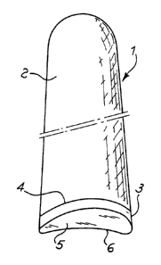
Figure 2 diagrammatically shows a perspective view of an implant 1 made
according to the invention: in the figure are visible the roughened surface of
the
body 2, the smooth neck 3, the line 4 that separates the body 2 from the neck
3
is and the final surface 5 of the neck 3, whose edge 6 has a profile basically
corresponding to that of the margin of the alveolar bone crest 9 in a state of
parodontal health, omitted in figure 2 (together with gum 18) for ease of
illustration
and shown in figures 3 and 4 by a dotted line.
At the front and back side of the artificial tooth 7 supported by implant 1
(figure 4),
2o the edge 6 of the final surface 5 of the neck 3 of the implant 1 has a
curved profile
with its convexity directed towards the base of the bone 9, whereas at the
side
faces of the artificial tooth 7 the edge 6 of the final surface 5 of the neck
3 of the
implant 1 has a curved profile with its concavity directed towards the base of
the
bone 9.
2s To highlight this particular profile of edge 6 of the final surface 5 of
neck 3, figure 2
omits the prosthetic stump 10 (figure 8) and the artificial tooth 7.
Figure 3 diagrammatically shows a frontal view of an area of the upper dental
arch
including an artificial tooth 7 made by a known type implant 11 (figures 1 and
9.a)
and placed between two natural teeth 8.
3o The artificial tooth 7 is supported by the prosthetic stump 10, in turn
fixed to the
known type implant 11; moreover, in figure 3 are diagrammatically shown the
gum
edge, denoted by 13, and the margin 14 of the crest of the bone 9, basically
CA 02377042 2002-O1-28
WO 01/06944 PCT/EP00/07024
6
parallel to the edge 13 of the gum, being a distance 15 away, corresponding to
the
so-called "biological depth".
In figures 3 to 7, the roots of the natural teeth 8, respectively the
prosthetic stump
and the implant (11, respectively 1 ) of the artificial tooth 7 are "see-
through"
s visible inside the bone 9, with the gum 18 being omitted for ease of
illustration.
As already said previously and clearly shown in figure 3, the contact line 12
between the prosthetic stump 10 and the final surface of the neck of the
implant
11 is straight: accordingly at the artificial tooth 7 the edge 13 of the gum
and the
margin 14 of the crest of the bone 9 follows a (basically) flat circular
course,
to differing from that around the natural teeth 8 due to the fact that the
"osseous
papillae" 16 are virtually absent and the interdental papillae 17 of the gum
are
much less developed.
Figure 4 outlines a front view of an area of the upper dental arch including
an
artificial tooth 7 made by an implant 1, according to the invention, and
placed
is between two natural teeth 8.
The artificial tooth 7 is supported by the prosthetic stump 10, in turn fixed
to the
implant, according to the invention 1; moreover in figure 4 are outlined the
edge 13
of the gum and the margin 14 of the crest of the bone 9, basically parallel to
the
edge 13 of the gum, being a distance 15 away, corresponding to the so-called
"biological depth".
As figure 4 clearly shows, the contact line between the prosthetic stump 10
and
implant 1 (formed by the front part of edge 6 of the final surface 5 of the
neck 3 of
implant 1 and by the corresponding area of the edge of contact surface 5'
[figure 8]
of the prosthetic stump 10) follows a (basically) curvilinear course
coinciding with
2s those of edge 13 of the gum and of margin 14 of the crest of the bone 9 at
a
natural tooth 8: accordingly the presence of the artificial tooth 7 does not
alter the
profiles of edge 13 of the gum and of the margin 14 of the crest of the bone 9
and,
above all, the interdental papillae 17 and the corresponding "osseous
papillae" 16
(clearly visible between two adjacent natural teeth 8) are present and also
well
3o developed at the sides of the artificial tooth 7, allowing the attainment
of previously
highlighted aesthetic-practical advantages.
In order to achieve the aforesaid aesthetic-practical advantages it is
necessary (or
CA 02377042 2002-O1-28
WO 01/06944 PCT/EP00/07024
7
advisable, at least) that:
- implant 1 should be inserted in the bone 9 so that the edge areas 6 of the
final
surface 5 of its neck 3 with its convexity directed towards the base of the
bone 9
are placed at the front face, corresponding to the back one of the artificial
tooth 7:
s a thus positioned implant 1 closely follows (as far as possible) the
architecture of
the bone 9 in a natural arch and the treated and roughened surface of its body
2
helps and guides bone 9 regeneration and particularly the "osseous papillae"
16
that support the interdental papillae 17;
- implant 1 should be joined to a prosthetic stump 10 having a contact surface
5'
io (figure 8), the shape of which complements that of the final surface 5 of
the neck 3
of the implant 1, thus achieving improved connection stability between the
implant
1 and the prosthetic stump 10 since the contact surfaces (5, 5') are not flat
(as the
contact surfaces for a known type implant 11 ) and therefore making it
(virtually)
impossible that the prosthetic stump 10 rotates with respect to the implant 1,
is reducing the probability of the consequent loosening of the internal fixing
screw.
These advantages greatly compensate for the higher production costs arising
from
the need to produce contact surfaces (not flat) complementary with each other
and
suitable to join together with (virtually) no clearance.
Figures 5 to 7 show, respectively, a side view of a natural tooth 8, an
artificial tooth
Zo 7 made by an implant 11 of known type and an artificial tooth 7 made by an
implant 1 according to the invention, placed in a (natural, respectively
artificial)
socket in bone 9 and covered by the gum; for ease of illustration, in figures
5 to 7
only the edge 13 of the gum and the margin 14 of the crest of the bone 9 are
shown, explicitly omitting the "body" of the gum and the bone 9.
2s Comparison of the side view of the natural tooth 8 (figure 5) with those of
an
artificial tooth 7 made by an implant 1 according to the invention (figure 7),
respectively by an implant 11 of known type (figure 6), clearly shows that,
using an
implant 1 according to the invention (figure 7), the "osseous papillae" 16 and
interdental papillae 17 (supported by the "osseous papillae" 16) are clearly
present
3o and naturally developed, whereas using an implant 11 of known type (figure
6) the
"osseous papillae" 16 are absent, making the long term preservation of the
interdental papillae 17 much more difficult.
CA 02377042 2002-O1-28
WO 01/06944 PCT/EP00/07024
8
In fact, in figure 7 the course of edge 13 of the gum and that of margin 14 of
the
crest of the bone 9 (and, accordingly, the shape and dimensions of the
"osseous
papillae" 16 and of the interdental ones 17) are virtually identical to those
found at
a natural tooth 8 (figure 5), whereas in figure 6 the edge 13 of the gum and
that of
s margin 14 of the crest of the bone 9, seen sideways, follow a (virtually)
straight
course and, accordingly, the "osseous papillae" 16 and the interdental
papillae 17
are (virtually) absent.
Figure 8 diagrammatically shows an implant 1 made according to the invention
and the relevant prosthetic stump 10, having a contact surface 5' the shape of
io which exactly complements that of the final surface 5 of the implant 1
neck.
Moreover, in figure 8 is visible the recess 20 made in the body 2 of the
implant 1
and suitable to accommodate the polygonal part 20' of the prosthetic stump 10
that, combined with the special shape of the contact surfaces (5, 5') of the
implant
1 and the prosthetic stump 10, helps to further reduce the chances of the
is prosthetic stump 10 rotating with respect to the implant 1.
Figure 9 outlines a known type implant 11 and an implant 1 made according to
the
invention; in particular:
- Figure 9.a diagrammatically shows a known type implant 11, whose final
surface
is flat and in the body 2 of which is made the recess 20 able to accommodate
the
2o polygonal portion of the relevant prosthetic stump 10, not shown in figure
9.a;
- Figure 9.b diagrammatically shows an implant 1 made according to the
invention,
whose final surface 5 is shaped according to the invention: in body 2 of
implant 1
is made the recess 20 able to accommodate the polygonal portion of the
relevant
prosthetic stump 10 (figure 8).
2s Without leading away from the scope of the invention it is possible for a
person
skilled in the art to make all the modifications and improvements to the
device for
dental implantation, subject of the present description, suggested by normal
experience and by the natural development of the technique.