Note: Descriptions are shown in the official language in which they were submitted.
CA 02377353 2001-12-12
WO 00/68842 PCT/US00/13163
NAVIGATING DATA POINTS IN A MULTIDIMENSIONAL DATABASE
Field of the Invention
The present invention relates generally to a method and apparatus for
visually displaying data, and more specifically, to a method and apparatus
for navigating and displaying data points stored in a multidimensional
database.
Background of the Invention
The data in a multidimensional information system can be defined (or
arranged) along multiple dimensions. For example, the data in a sales
management system may include time, location, customer, and product
dimensions. A dimension may include many members. The members in
one dimension can be organized as a hierarchical tree with multiple levels.
Figure 1 shows an exemplary dimension tree for the data along a
product dimension; in which "All Products" is a member; "Furniture" is a
member; "Electronics" is a member; "Beds" is a member; and so on. In the
dimensional tree, the upward connections are called parent connections,
and the downward connections are called child connections. "All Products"
is the first level member in the dimension tree; "Furniture" and
"Electronics" are the second level members in the dimension tree; "Desks",
"Chairs", "Beds", "Home Appliance", and "Office Equipment" are the third
level members in the dimension tree; and so on. "Furniture" is the parent
of "Desks", "Chairs", and "Beds"; "Furniture" and "Electronics" are children
of "All Products"; and so on. A member without a parent is called root
member. Specifically, "All Products" is a root member.
In a multidimensional database system having N dimensions with
multiple levels per dimension, a data point (or cell) is defined as the
intersection of one member from each dimension. The N dimensions form a
cube, which contains all data points in the database system. Thus, the
more dimensions and levels per dimension, the more complex is the
1
CA 02377353 2008-02-13
WO 00/68842 PCTIUSOO/13163
neighboring data points surrounding a given data point. For example, in an
N-dimensional database with each dimension having only one level, each
data point in the database has 2N immediate neighboring data points or
navigation directions. The multidimensional information system are
described in greater detail in OLAP Solutions by Erik Thomsen published in
1997.
Thus, efforts have been made to develop tools for facilitating users
to navigate through multidimensional database and display data points that
are being navigated along multiple dimensions. However, the existing data
navigation and display tools does not provide the flexibility in navigating
data points along multiple dimensions. Specifically, in the existing data
navigation and display tools, the navigation paths are limited by the
hierarchical structure of the multidimensional database. Thus, a user may
not be able to navigate through a multidimensional database in a sequence
of paths that fits the user's thought process. In addition, the existing data
navigation and display tool displays the data points separately on a
computer screen. Thus, it does not present a comprehensive view for the
data points that are being navigated.
Furthermore, the existing data navigation and display tool processes
multidimensional data points within a single dimensional hierarchy. To
change a dimension in the middle of a data navigation process, a user has
to perform a so called "pivotal" process to bring a new dimension into
focus. In doing so, the user may lose the navigation paths previously
performed, thus losing the context and importance of the piece of data that
is being currently displayed on the computer screen. Also, such a "pivotal"
process is relatively complicated and not easy for an average user to grasp.
There is, therefore, a need for an improved method and apparatus
that provide flexible navigation paths through the data points in a
multidimensional database.
2
CA 02377353 2001-12-12
WO 00/68842 PCT/US00/13163
There is another need for an improved method and apparatus that
provide users with a comprehensive graphical view of the data points
stored in a multidimensional database, while the data points are being
navigated.
There is yet another need to provide an improved method and
apparatus for navigating and displaying the data points stored in a
multidimensional database, which are easier for users to use.
The present invention provides such a method and apparatus to meet
these three needs.
Summary of the Invention
To overcome the shortcomings in the existing art, the present
invention provides a novel method for displaying data points stored in a
multidimensional database.
In a broad aspect, the invention provides a method for displaying
data points stored in a multidimensional database. The data points are
defined along at least two dimensions. The method comprises the steps of:
extracting a parent data point from the multidimensional database;
displaying the parent data point as a parent data point icon in a data point
tree; selecting the parent data point icon from the data point tree;
extracting, from the multidimensional database, a plurality of child data
points under the parent data point along one of the at least two
dimensions; and displaying the child data points as respective icons in the
data point tree, together with the relationships between the parent data
point and the child data points.
The present invention also provides a corresponding apparatus to
perform the steps described in the above method
Brief Description of the Drawings
The purpose and advantages of the present invention will be
apparent to those skilled in the art from the following detailed description
in
conjunction with the appended drawing, in which:
3
12-Mar-01 13:5A From-CROSBY HEAFEY ROACH MAY SF
4156596695rUT
FOO11
22048.00240 =4t$ )&> toot
Figure 1 shows an exemplary dimension tree for the data along a
product dimension;
Figure 2 is a block diagram showing a system for displaying a
decomposition tree, in accordance with the present Invention
Figure 3 shows a hierarchy structure of an exemplary
multidimensional database, which will be used to demonstrate the process
of displaying a decomposition tree, in accordance with the present
invention
Figure 4A shows a hierarchy structure of the Product dimension
shown in Figure 3;
Figure 413 shows a hierarchy structure of the Regions dimension
shown in Figure 3
Figure 4C shows a hierarchy structure of the Time dimension shown
in Figure 3
Figure 4L shows a hierarchy structure of the Customer dimension
shown in Figure 3;
Figure 5 shows a screen shot illustrating a user graphic interface for
invoking the Dtree program of the present invention;
Figure 6 shows a screen shot illustrating a step of creating a session
and linking the session to a miitidimensi=anal database;
Figure 7 shows a screen shot illustrating a screen shot of selecting a
measure for viewing;
Figure 8 shows a screen shot illustrating a step of selecting a root
(starting) data point for the decompositi 3n tree;
Figure 9 shows a screen shot illustrating a step of selecting a
dimension and level for viewing;
Figure 10 shows a screen shot illustrating the decomposition tree
along the "Customers" dimension at the "Channel" level
Figure 11 shows a screen shot illustrating a step of skipping the
"Channel" level along the "Customers" dimension;
4
MFW&f
CA 02377353 2001-12-12
12-Mar-01 13:58 From-CROSBY HEAFEY ROACH MAY SF
4156585685 0
22048.00240 i
Figure 12 shows a screen shot illustrating that the root data point
("All Customers" data point) is broken down to the "Customer Sectors";
Figure 13 shows a screen shot illustrating a step of displaying the
child data points under the "Reseller" data point;
Figure 14 shows a screen shot illustrating a step of displaying the
child data points under the "Corporate" data point:
Figure 16 shows a screen shot illustrating a step of shifting (or
splitting) the data points grouped in the "B-attom" data point icon onto the
screen
Figure 16 shows a screen shot illustrating a step of changing
dimension at a data point from which the decomposition tree is further
broken down;
Figure 17 shows a screen shot illustrating that the "Corporate" data
point is broken down along the "Regions" dimension at the "Country" level;
Figure 18 shows a screen shot illustrating a step of displaying the
child data points under the "Educational" data point;
Figure 19 shows a screen shot illustrating a step of selecting a level
based on which the "USA" data point will be further broken down;
Figure 20 shows a screen shot illustrating the decomposition tree
resulting from the user's selection in the screen shot shown in Figure 19;
Figure 21 shows a screen shot illustrating a step of changing
dimension at "Austin" data point;
Figure 22 shows a screen shot illustrating the decomposition tree
resulting from the user's selection in Figure 21;
Figure 23 shows a screen shot illustrating a step of changing the
breaking down level along the "Product" dimension at the "Educational"
data point;
Figure 24 shows a screen shot illustrating the decomposition tree
resulting from the user's selection in Figure 23;
5
CA 02377353 2001-12-12
CA 02377353 2001-12-12
WO 00/68842 PCTNS00/13163
Figure 25 shows a screen shot illustrating a step of changing
measure for decomposition tree;
Figure 26 shows a screen shot illustrating a measure menu;
Figure 27 shows a screen shot illustrating the decomposition tree
resulting from the user's selection in Figure 26;
Figures 28A-B are two flowcharts for forming a decomposition tree;
and
Figure 29 is a block diagram of a computer system, which can be
used as a hardware platform for running the program to perform the
process shown in Figures 5-27 and 28A-B.
Detailed Description of the Preferred Embodiment
The following description is presented to enable any person skilled in
the art to make and use the invention, and is provided in the context of a
particular application and its requirements. Various modifications to the
preferred embodiments will be readily apparent to those skilled in the art,
and the principles defined herein may be applied to other embodiments and
applications without departing from the spirit and scope of the invention.
Thus, the present invention is not intended to be limited to the
embodiments shown, but is to be accorded with the broadest scope
consistent with the principles and features disclosed herein.
Figure 2 is a block diagram showing a system 200 for displaying a
decomposition tree containing the data points that are stored in a
multidimensional database, in accordance with the present invention.
As shown in figure 2, the system 200 includes a graphic user
interface 206 that is displayed on a computer monitor screen, a
decomposition tree (Dtree) program 208, an OLAP (On Line Analysis
Processing) database API (Application Interface) 210, an OLAP
multidimensional database server (OLAP server) 212, and a
multidimensional database (OLAP database) 214.
6
CA 02377353 2001-12-12
WO 00/68842 PCT/US00/13163
The OLAP database 214 stores data in multidimensional format, and
the structural information (called meta-data) about the data. The OLAP
server 212 manages the multidimensional data stored in the OLAP database
214. Specifically, the OLAP server 212 allows users to define the
structure of the multidimensional data, load data into the OLAP database
214, and execute data queries over data in the OLAP database 214. The
OLAP database API 210 receives data queries from the Dtree program 208,
sends them to the OLAP server 212, and receives resulting information
from the OLAP server 212. A commercial available OLAP database API is
the OLE-DB for OLAP, published by Microsoft Corporation and implemented
in several OLAP products. Information queried from the OLAP server 212
takes two forms: (1) meta-data, and (2) user data. Meta-data, which
describes the structure and contents of the OLAP database 214, consists
of available data files, cubes, dimensions, levels, measures, etc.
Interacting with the graphic user interface 206 by using a mouse and
a keyboard (not shown), a user can communicate with the Dtree program
208, sending control requests and data queries to the Dtree program 208.
In response to the control requests (such as selections or changes on
dimensions, measures, and levels) from the user, the Dtree program 208
sets the decomposing parameters for displaying a decomposition tree. In
response to the data queries, the Dtree program 208 retrieves the meta-
data from the OLAP database API 210 and presents the meta-data as menu
options to the user as to the structure of the data points in the OLAP
database 214. When the user indicates, via the graphic user interface 206,
to the Dtree program 208 which data point is of interest and which
structure element (i.e. dimension and level) he/she wants to break down,
the Dtree program 208 issues a data query to the OLAP database API 210.
Upon receiving the data values of the data points of interest, the Dtree
program 208 displays the data points and data values in a tree format to
the user, according to the structure defined by the meta-data.
7
12-tsar-01 14:00 From-CROSBY HEAFEY ROACH 14AY SF
4156505895 ~J~dB~
! 1 3 1.6 3
22048.00240
IPEA4JS 12 MAR 2001
Figure 3 shows a hierarchy structure of an exemplary
multidimensional database, which will be used to demonstrate the process
of displaying a decomposition tree below, ire accordance with the present
invention.
As shown in Figure 3, the database structure 300 includes four
dimensions: Time, Customers, Regions, and Products. The "Time"
dimension is divided into three levels: Year, Quarter, and Month. The
"Customers" dimension is divided into three levels: Channel, Sector, and
Name. The "Regions" dimension is divided into four levels: Region,
Country, State Province, and City. The "Products" dimension is divided
into three levels: Line, Family, and Itemnarne. The four dimensions form a
cube, which contains all data points in the multidimensional database. The
database structure 300 further includes Measures having three individual
measures: Quantity, Sale, and Profit. Measures are quantitative values in
the space cube. Each of the data points in the OLAP database 214 has its
respective values relating to these three measures.
Figure 4A shows a hierarchy structure of the "Products" dimension
shown in Figure 3. In Figure 4A, the "Products" dimension has a root
member "All-Products", which connects to three child members:
Accessories, PCs, and Services. The "Ac;cessories" member connects to
six child members: Cables, Hubs, Miscellaneous, Modems, NICs, and
Printers. The "Hub" member further connects to six child members:
CentraiHub 53, CentraiHub 59, CentraiHub 62, NetMax 171, NetMax 173,
and NetMax 174. The "PCs" member connects to four child members:
Business PCs, Home PCs, Laptops, and Servers. The "Services" member
connects to three child members: Consi lting, Miscellaneous Services, and
Training.
Figure 4B shows a hierarchy structure of the "Regions" dimension of
Figure 3. Figure 4C shows a hierarchy structure of the "Time" dimension
of Figure 3. Figure 4D shows a hierarchy structure of the "Customers"
8
7
CA 02377353 2001-12-12
CA 02377353 2001-12-12
WO 00/68842 PCTIUSOO/13163
dimension of Figure 3. The hierarchy structures in Figures 4B-D can be
broken down using a similar process described in connection with Figure
4A.
Figures 5-25 show a sequence of screen shots illustrating a process
of navigating through a plurality of data points and displaying them in the
decomposition tree on a computer monitor screen, in accordance with the
present invention.
In describing the process, it is assumed that the data points to be
displayed have been stored in the OLAP database 214 with a structure as
defined in Figures 3 and 4A-D. A user is navigating through the data points
by using a mouse having a right button and a left button (not shown).
These data points will be represented as data point icons on the monitor
screen. The user can select a data point by left-clicking on the data point
icon that represents the data point. By the same token, the user can select
an item contained in a menu or pull-down list by left-clicking on the item.
Each of the data points associates with a menu containing the information
(meta-data) about the structure of the data point. The user can invoke
(select) a menus that is associated with a data point by right-clicking on a
corresponding data point icon. The decomposition tree also associates with
a menu. The user can invoke the menu that is associated with the
decomposition tree by right-clicking a vacant area on the screen shots
shown in Figures 5-25.
Figure 5 shows a screen shot illustrating a graphic user interface 500
for invoking the Dtree program 208 produced by Knosys, Inc. To start the
Dtree program 208, the user left-clicks on (selects) the "View" button 502.
In response to the user's selection, the Dtree program 208 displays the
screen shot 600, as shown in Figure 6.
Figure 6 shows a screen shot illustrating a step of creating a session
for displaying a decomposition tree, and of linking the session to the OLAP
database 214. As shown in Figure 6, a pull-down list 602 is displayed on
9
11-Ihr-01 14:00 Frog-CROSBY HEAFEY ROACH MAY SF 4156595695 OtJtfl r/ ! 163
22048.00240 )PE PS 12 MAR 2001
the screen shot 600. In response to user's left-click on (selection of) the
"View 1 Type" item 603 in the pull down list 602, a second level pull-down
list 604 is displayed on the screen shot 60Ci. In response to user's left-
click on (selection of) the "Advanced Analysis Tools" item 606 in the pull-
s down list 604, a third level pull-down list 638 is displayed on the screen
shot 600. In response to user's left-click on (selection of) the
"Decomposition Tree" item 610 in the pull-down list 608, the Dtree
program 208 displays the screen shot 700 as shown in Figure 7 on the
screen. The user's left-click on (selection of) the "Decomposition Tree"
item 610 causes the Dtree program 208 to create a session for the process
and link the session to the OLAP database 214.
Figures 7-9 show three screen shots allowing the user to set
decomposing parameters (measure, sorting order, dimension, level, etc) for
the decomposition tree to be formed.
Figure 7 shows the screen shot 700 illustrating a step of selecting a
measure for viewing. As shown in Figure 7, the user left-clicks on (selects)
"Sales" from the pull-down list 704 as a measure so that a respective sales
value in the OLAP database 214 will be displayed together with each of the
data points in the decomposition tree. Further, the user left-clicks on
(selects) the "Biggest Items" as sorting order so that the data points in the
decomposing process will be sorted in a descending order. If the user had
selected the "Smallest item" as sorting order, the data points in the
decomposition tree would be sorted in an ascending order. In response to
the user's selection of the "Next" button 610 in the screen shot 600, the
Dtree program 208 displays the screen :shot 800 as shown in Figure 8.
Figure 8 shows the screen shot 800 illustrating a step of selecting a
root (starting) data point for the decomposition tree. As shown in Figure 8,
the "All Customers" data point is selected, as indicated by highlighted
display. In response to the user's selection of the "Next" button, the Dtree
program 208 displays the screen shot 900 as shown in Figure 9.
MWW
7
CA 02377353 2001-12-12
12-Mar-01 14:00 From-CROSBY HEAFEY ROACH MAY SF
4166595695 ~~ 1 6
22048.00240 W ;/ S 12 MAR 2001
Figure 9 shows the screen shot 900 illustrating a step of selecting a
dimension and level to begin the decomposing process. As shown in Figure
9, the user left-clicks on (selects) the "Customer" dimension and the
"Channel" level, as indicated by the highlighted display. The Dtree program
208 maintains and automatically updates (if necessary) the decomposing
parameters (including measure, sorting order, dimension, level, and root
data point) selected by the user, and uses them in the decomposing
process. However, as will be described below, the user can change
decomposing parameters in the middle of the decomposing process. In
response to user left-click on (selection of) the "Finish" button, the Dtree
program 208 displays the screen shot 1000, as shown in Figure 10.
Figure 10 shows the screen shot 1000 illustrating the decomposition
tree including three data point icons that represent three data points. At
the root level is the "All Customers" data point, which is broken down
along the "Customers" dimension at the Channel" level. As shown in
Figure 10, the 'All Customers" data point connects to two child data
points: an "Indirect Channel" data point End a "Direct Channel" data point.
The "Indirect Channel" and "Direct Channel" data points have sales of 83M
(million) and 79M, respectively; and contribute 51 % and 49% of the sales
measure respectively to the "All Customers" data point. These two data
points are displayed according to a descending order according to the sales
measure, specified in the screen shot 7C0. The relationships between the
"All Customers" data point and the two "Channel" data points are
represented by the connecting lines between them.
Figure 11 shows the screen shot 1100 illustrating a step of skipping
the "Channel" level in the "Customers" dimension. As shown in Figure 11,
the user right-clicks on (selects) the "All Customers" data point icon to
display a dimension menu associated with the "Alf Customers" data point.
In response, the Dtree program 208 displays a pull-down list 1102 on the
screen. The pull-down list 1102 contains four dimension options
11
MET-
CA 02377353 2001-12-12
12-Mar-01 14:00 From-CROSBY HEAFEY ROACH MAY SF
4186695696 Aftft~Ak A6.&
22048.00240 747 111
RM, 1 MAR 20
(Customers, Products, Regions, and Time). To display a level menu
associated with the "Customers" dimension, the user further left-clicks on
(selects) the "Customers" dimension in the pull-down list 1102. In
response, the Dtree program 208 displays a pull-down list 1106, which
contains three level options (Channel - the first level, Sector - the second
level, and Name - the third level) along the "Customers" dimension. To
skip the "Channel" level, the user left-clicks (selects) "Sector" level in the
pull-down list 1106. The user's selection of "Sector" level causes the
Dtree program 208 to break the "All Customers" data point down to
"Customers Sectors" along the "Customer.;" dimension. In response to the
user's selection of the "Sector" level, the 13tree program displays the
screen shot 1200 shown in Figure 12.
Figure 12 shows the screen shot 12.00 illustrating that the "All
Customers" data point is broken down to the "Customer Sectors", skipping
the "Channel" level along the "Customers" dimension. As shown in Figure
12, the "All Customers" data point is broken down to eight "Customer
Sector" data points, which are represented by eight data point icons:
Reseller, Corporate, Government, Distributor, Education, and OEM. These
six "Customer Sector" data points have sales of 158M, 80M, 69M, 17M,
10M, -3M, respectively; and they are disolayed in a descending order
according to the sales measure. These six data points make up the
contributes of 48%, 24%, 21%, 5%, 3%, and -1 % of the sales to the "All
Customers" data point.
Figure 13 shows a screen shot 1300 illustrating a step of displaying
the child data points under the "Reseller" data point. To display the child
data points under the "Reseller" data point, the user left-clicks on (selects)
the "Reseller" data point icon. In response, the Dtree program 208
retrieves 328 data points under the "Reseller" data point from the OLAP
database 214, and displays six child data point icons to represent the 328
data points. It can be noticed that the Dtree program 208 groups 323 child
12
CA 02377353 2001-12-12
12-Mar-01 14:01 From-CROSBY HEAFEY ROACH MAY SF 4156595695
22048.00240 '"JPOV
12 MAR 2001
data points having the lowest sales values into the "Bottom" data icon, so
that all the child data points under the "Reseller" data point can be
displayed in the monitor screen. Had the "Smallest Items" been selected in
the screen shot 700, the Dtree program 203 would group 323 child data
points having the highest sales values into a "Top" data icon. As shown in
the screen shot 1300, the aggregation of the Sales values In the six child
data point icons equals to the total sales value in the "Reseller" data point.
Again, the six data point icons are displayed in a descending order
according to Sales value.
Figure 14 shows a screen shot 1400 illustrating a stop of displaying
the child data points under the "Corporate" data point. To display the child
data points under the "Corporate" data point, the user left-clicks on
(selects) the "Corporate" data point icon. In response, the Dtree program
208 retrieves 167 child data points under the "Corporate" data point, and
displays seven child data point icons to represent the 157 child data points.
In the meantime, the Dtree program 208 Erases the six data point icons
under the "Reseller" data point. It can be noticed that the Dtree program
208 groups 151 child data points having the lowest sales values into the
"Bottom" data icon, so that all the child data points under the "Corporate"
data point can be displayed on the monitor screen. Had the "Smallest
items" been selected in the screen shot 700, the Dtree program 208 would
group 151 child data points having the highest sales values into a "Top"
data icon.
Figure 15 shows a screen shot 1500 illustrating a step of shifting (or
splitting) the data points grouped in the "Bottom" data point icon onto the
monitor screen. To display a child data point having the highest sales value
in the "Bottom" data point icon, the use,- left-clicks on (selects) the
"Bottom" data point icon once. In response, the Dtree program 208 shifts
the child data point having the highest sales out of the "Bottom" data icon,
and displays a data point icon to represent the data point that has been
13
CA 02377353 2001-12-12
12-Mar-01 14:01 Fr=-CROSBY HEAFEY ROACH MAY SF 4156595695
lP.12/27 F-460
22048.00240
1P q/ ` 2 VAR 2001
shifted out of the grouped data icon. In the means time, the Dtree program
208 groups the data point Icon having the second highest sales value into
the data point icon having the highest sales value. Specifically, to display
five data points having the highest sales in he "Bottom" data point icon,
the user left-clicks on (selects) the *Bottom" data icon in Figure 1400 five
times. In response, the Dtree program 208 displays five data point icons to
represent the five data points having the highest sales in the "Bottom" data
point icon. These five shifted data points are: Kenduskeag System,
Nooksack Distribution, Majestic Inc., Heartwell War, and Sewanee Inc. In
the meantime, the Dtree program 208 groups the six data point icons in the
screen shot 1400 into a "Top" data point. These six grouped data points
are: Eldena Networks, Laconia Syste, Gumberry Company, Oakridge
Distribution, Laupahoehoe, and Basin Technology.
Figure 16 shows a screen shot 1600 illustrating a step of changing
dimension at a data point from which the decomposition tree is further
broken down. To change the dimension at the "Corporate" data point, the
user right-clicks on (selects) the "Corporate" data point icon. In response,
the Dtree program 208 displays a dimension menu associated with the
"Corporate" data point at the "Sector" le' el in a pull-down list 1604. in
response to user's right-click on (selection of) "Regions" dimension in the
pull-down list 1604, the Dtree program 208 further displays a level menu in
a pull-down list 1606. In response to user's left-click on (selection of)
"Country" level in the pull-down list 1605, the Dtree program 208 changes
the dimension from "Customers" to "Regions", and displays the screen shot
1700 as shown in Figure 17.
Figure 17 show the screen shot 1700 illustrating that the
"Corporate" data point is broken down along the "Regions" dimension at
"Country" level. It should be noted that in the decomposition tree shown in
the screen shot 1700, the "Region" level along the "Regions" dimension is
skipped.
14
A"ODCA 02377353 2001-12-12
12-Mar-01 14:01 From-CROSBY HEAFEY ROACH MAY SF
41565li56A5
22048.00240 W*VS 12 MAR 2001
Figure 18 shows a screen shot 1800 illustrating a step of displaying
the child data points under the "Educational" data point. To break down
the "Educational" data point, the user left-clicks on (selects) on the
"Educational" data point icon in Figure 17. In response, the Dtree program
208 retrieves the 21 data points under the "Educational" data point from
the OLAP database 214, and displays seven child data point icons to
represent the 21 data points. because the dimension has been changed
from the "Customers" dimension to the "Regions" dimension at the
"Country" level in the screen shot 1600, the "Educational" data point is
broken down along the "Region" dimension at "Country" level. It can be
noticed that the countries in the seven data point icons in the screen shot
1800 are the same with those in the screen shot 1700. However, the
sales values and display sequence of the seven "Country" data point icons
are changed in the screen shot 1800. For example, in the screen shot
1700, Spain is the fifth country in sales (2M) for the "Corporate Sector".
In the screen shot 1800, Spain is the second country in sales (661 K) for
the "Educational Sector".
Figure 19 shows a screen shot 1900 illustrating a step of selecting a
level based on which the "USA" data point will be further broken down. To
do so, the user right-clicks on (selects) the "USA" data point Icon. In
response, the Dtree program 208 displays a dimension menu in a pull-down
list 1904. In response to user's right-click on (selection of) the "Regions"
dimension in the pull-down list 1904, thti Dtree program 208 further
displays a level menu in a pull-down list 1906. It can be noticed that the
first two levels of the "Regions" dimension are not available in the level
menu, because the "USA" data point is located at the "Country" level along
the "Regions" dimension. The Otree program 208 automatically updated
the decomposing parameters in the decomposing process. Thus, the
"USA" data point can only be broken down by the levels below the
"Country" level. To select the "City" level, the user left-clicks on (selects)
CA 02377353 2001-12-12
12-Mar-01 14:02 From-CROSBY HEAFEY ROACH IMY SF
4156595605 / ~0~ ~t
V
22048.00240 /
2 MAR 2001
on the "City" level from the pull-down list 1906. In response, the Dtree
program 208 displays the screen shot 2000 as shown in Figure 20, to
break down the "USA" data point to the "City" level along the "Regions"
dimension.
Figure 20 shows the screen shot 20130 illustrating the decomposition
tree resulting from the user's selection in the screen shot 1900. The
decomposition tree in the screen shot 2000 can reflect user's analysis
process, or train-of-thought. As shown in the screen shot 2000, the
"Education Sector" is the fifth Sector in terms of sales, the USA is the
country having the largest sales (71 % of an educational sales) in the
"Educational Sector", and Austin is the city having the largest sales (9% of
all educational sales) in the "Educational Sector" within the USA.
Figure 21 shows a screen shot 2100 illustrating a step of changing
dimension at the "Austin" data point, so that the user can inquire "what
product families are the "Educational" customers in the city of Austin
buying?". To change the dimension at the "Austin" data point, the user
right-clicks on (selects) the "Austin" data point. In response, the Dtree
program 208 displays a dimension menu in a pull-down list 2104. In
response to user's right-click on (selection of) the 'Products" dimension in
the pull-down list 2104, the Dtree program 208 displays a level menu in a
pull-down list 2106. In response to user's right-click on (selection of) the
"Family" level in the pull-down list 2106, the Dtree program 208 changes
the dimension from "Regions" at "City" level to "Products" at "Family"
level. The Dtree program 208 then disp'ays the screen shot 2200 as
shown in Figure 22.
Figure 22 shows a screen shot 2200 illustrating the decomposition
tree resulting from the user's selection in the screen shot 2100. As shown
in Figure 22, the screen shot 2200 displays a decomposition tree having
five different levels of breaking down along three different dimensions. The
decomposition tree skipped four levels ..n the breaking down process: (1)
CA 02377353 2001-12-12
1.2-Mar-01 14:02 F roa-CROSBY HEAFEY ROACH MAY SF 4156595695 j 9 T Tit j /
1020 Spy=
22048.00240 IP /j4 12-MA-R-7001
the "Sector" level of the "Customers" dimension (skipping the "Channel"
level"), (2) the "Country" level of the "Regions" dimension (skipping the
`Region" level), (3) the "City" level of the "Regions" dimension (skipping
the "State Prov" level), and (4) the "Family" level of the "Products"
dimension (skipping the "Line" level). The decomposition tree presents the
user with a perspective view about the his/her analysis process. For
example, even though the USA has the largest sales in the "Educational"
sector, the City of Austin has the largest sales in the USA, and the Servers
product accounts 92% of sales in the City of Austin; the `Educational
Sector" itself counts only 3% of all sales. At this point, the user may need
to inquire whether the "Server Product Family" is that dominate across all
sales in the "Educational Sector". To do SD, the user needs to change the
break down level along the "Products" dimension at the "Educational" data
point, as will be shown in the screen shot 2300.
Figure 23 shows the screen shot 2:;00 illustrating a step of changing
the breaking down level along the "Product" dimension at the "Educational"
data point. To change the break down level along the "Product" dimension,
the user right-clicks on (selects) the "Educational" data point. In response,
the Dtree program 208 displays a dimension menu in a pull-down list 2304.
In response to user's right-click on (selection of) the "Products" dimension
in the pull-down list 2304, the Dtree program 208 displays a level menu in
a pull-down list 2306. In response to user's right-click on (selection of)
"Family" level in the pull-down list 2306, the Dtree program 208 displays
the screen shot 2400, to break down the "Educational" data point at the
"Family" level along the "Products" dimension.
Figure 24 shows the screen shot 2400 illustrating the decomposition
tree resulting from the user's selection in the screen shot 2300. As shown
in the screen shot 2400, the decomposition tree indicates that Servers
product has the largest sales across all sales in "Educational Sector".
However, in contrast to the Servers product sales in Austin which makes
17
CA 02377353 2001-12-12
12-Mar-01 14:02 From-CROSBY IIEAFEY ROACH MAY SF 4156505695 6 22048.00240 MTV
e I .y2 f!o T 6 3
1 Z MAR 2001
up 92% of the total sales within the City of Austin, the Servers product
sales across the "Educational Sector" accounts only 43% of all product
sales. The decomposition tree shown in the screen shot 2400 provides
additional information. Specifically, comparing with the decomposition tree
in the screen shot 2400, the "Training", "Miscellaneous Services", and
"Home PCs" product families did not even appear in the decomposition tree
shown in the screen shot 2300. This means that the "Training",
"Miscellaneous Services", and "Home PCs" product families did not have
any sales to "Educational Customers" in Austin. At this point, the user
may need to inquire the "Profit Margin" for the "Servers Product Family"
across the "Educational Sector". To do so,. the user needs to change the
measure at the "Educational" data point, a3 will be shown in the screen
shot 2500.
Figure 25 shows the screen shot 2500 illustrating a step of changing
measure for the decomposition tree. To change the measure for the whole
decomposition tree, the user right-clicks on (selects) a vacant area
(meaning it does not contain any data point icons). In response, the Dtree
program 208 displays a menu in a pull-down list 2504. In response to
user's right-click on (selection of) the "Measure" in the pull-down list 2504,
the Dtree program 208 displays a screen :shot 2600 as shown in Figure 26.
Figure 26 shows the screen shot 2,500 illustrating a step of changing
the measure for the decomposition tree. As shown in Figure 26, the screen
shot 2600 contains a measure menu in a pull-down list 2604. In response
to user's right-click on (selection of) the "Profit Margin" in the pull-down
list
2604, the Dtree program 208 displays the screen shot 2700, to display the
"Profit Margin" measures in the data point icons contained in the
decomposition tree shown in Figure 2705.
Figure 27 shows the screen shot .1700 illustrating the decomposition
tree resulting from the user's selection in the screen shot 2600. As shown
in the screen shot 2700, a "Profit Margin" measure is displayed within each
18 -
ANVIDWSW
JW
CA 02377353 2001-12-12
12-Isar-01 14:03 Fran-CROSBY HEAFEY ROACH MAY SF 41565056Q5 `
2FV
2048.00240 ".4" 11- AP 2
of the data point icons in the decomposition tree. It can be noticed that the
data points at both the "Sector" level and "Family" level are displayed in a
descending order according to the "Profit Margin" measure.
Figures 28A-8 are two flowcharts for forming a decomposition tree
in a data navigation process by a user, in accordance with the present
invention.
Figure 28A is a flowchart illustrating a process of selecting a root
data point for the decomposition tree, in accordance with the present
invention.
As shown in Figure 28A, at step 2802, the user sends a control
request, via the graphic user interface 206, to the Otree program 208 to
create a session. In response, the Otree program 208 creates a session
and links the session to a multidimensional database. (See Figure 6).
At step 2804, the user selects a root data point via the graphic user
interface 206.
At step 2806, the user selects decomposing parameters (including a
dimension, the level within the dimension, and a measure) via the graphic
user interface 206.
At step 2808, the Dtree program 208 sets the selected decomposing
parameters for breaking down the root da&:a point, in response to the
selections in steps 2804 and 2806.
At step 2812, the Dtree program 208 sends a data query to the
OLAP database API 210 to retrieve the root data point and the measure
value associated with the root data point.
At step 2814, the Dtree program 208 receives the root data point
and the associated measure value from the OLAP database API 210.
At step 2816, the Otree program 208 displays a root data point icon
on a computer monitor screen, together with the associated measure value,
to represent the root data point.
19
CA 02377353 2001-12-12
CA 02377353 2001-12-12
WO 00/68842 PCT/USO0/13163
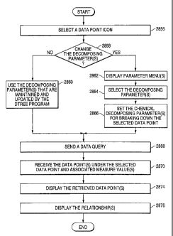
Figure 28B is a flowchart illustrating a process of breaking down a
data point that is being displayed on the decomposition tree, in accordance
with the present invention.
As shown in Figure 28B, at step 2856, the user selects a data point
icon (which represents a corresponding data point) from the decomposition
tree that is being displayed on the computer monitor screen by left-clicking
or right-clicking on the data point data icon. The user's selection causes
the graphic user interface 206 sends a control request to the Dtree program
208.
At step 2858, the Dtree program 208 determines whether the
decomposing parameters need to be changed. If the decomposing
parameters need to be changed (i.e. the user has selected the data point by
right-clicking on the data point icon, as shown in Figure 19 or 21), the
process is led to step 2862; if the decomposing parameters need not to be
changed (i.e. the user has selected the data point by left-clicking on
(selecting) the data point icon, as shown in Figure 13 or 14), the process is
led to step 2860.
At step 2860, if the decomposing parameters need not to be
changed, the Dtree program 208 uses the decomposing parameters that are
maintained in and updated by the Dtree program 208. The process is then
led to step 2868.
At step 2862, if the decomposing parameters need to be changed,
the Dtree program 208 displays parameter menu(s) containing parameter
options. (See Figure 19 or 21).
At step 2864, the user selects decomposing parameter(s) from the
parameter menu(s). (See Figure 19 or 21). The user's selection causes the
graphic user interface 206 to send a control request to the Dtree program
208.
At step 2866, the Dtree program 208 sets the changed decomposing
parameter(s) for breaking down the selected data point.
12-Mar-01 14:03 Froc-CROSBY I AFEY ROACH MAY SF
4156585685 fe O Q 1716
3
22048.00240 `P 'J; I ~ MAR 200)
At step 2868, the Dtree program 208 sends a data query to the
OL AP database API 210 to retrieve the data point(s) under the selected
data point and the measure value(s) associated with the data point(s) to be
retrieved. In the present invention, the Dtree program 208 requests the
OLAP database API 210 to return the data point(s) in a sorted order
according to the measure value(s).
At step 2870, the Dtree program 20.3 receives the data paint(s)
under the selected data point and the associated measure value(s) from the
OLAP database API 210.
At step 2874, the Dtree program 208 displays data point icon(s) on
the computer monitor screen, together with the associated measure
value(s), to represent the retrieved data pcint(s). The retrieved data
point(s) is/are displayed in an order according to the sorted measure
value(s).
At step 2876, the Dtree program 208 displays the relationship(s)
between the selected data point and the retrieved data point(s).
It should be appreciated that the present invention facilitates a user
to explore the values and relationships among the data points in a
multidimensional database by displaying these data points in a
decomposition tree. The decomposition tree allows a user to easily
navigate through N-dimensional data and quickly find the underlying values
that are driving the aggregated measure values. With this decomposition
tree, a user can navigate vertically through multiple layers into the data
points that make up a parent data point and horizontally across multiple
dimensions while maintaining a vertical perspective of the navigation paths
within the multidimensional database. Specifically, the decomposition tree
provides the following features and advantages:
1. The user may start a decomposition tree at any data point in a
multidimensional database.
21
CA 02377353 2001-12-12
12-Mar-01 14:03 From-CROSBY HEAFEY ROACH MAY SF
4156565605 2 4
22048.00240 2. The user can decompose any data point to any of its descendent
levels along any dimension. The descendent levels may be
skipped.
3. Once the user has selected the descendents from a dimensional
level, those descendents are combined with the positional location
from the other dimensions to derive the set of data points,
referred to as the decomposition data point set.
4. Decomposition data points are sorted based on their measure
value, and are displayed to the user in the order according to each
data point's contribution.
5. The user can select any data point on the decomposition tree,
making the selected data point the root data point of a new
decomposition tree.
6. If a selected decomposition data set has more data points that
can be displayed on the computer monitor screen, the
decomposition tree automatically places all data points that
cannot be displayed into a "group" data point representing the
aggregation of all data points in that group.
7. The user can shift the data points in a "group" data point left or
right to reveal the data points in the "group" data point.
8. Any data point in the decomposition tree can be selected and
decomposed by any of its available descendent levels within any
dimension in the multidimensional database.
Figure 29 shows a block diagram of a computer system 2900, which
can be used as a hardware platform for running the program to form the
decomposition tree in the present invention.
As shown in Figure 29, the computer system comprises a processing
unit 2902, a memory device 2904, a hard disk 2906, a disk drive interface
2908, a display monitor 2910 (includinci a computer monitor screen), a
22
AM W
CA 02377353 2001-12-12
CA 02377353 2008-02-13
WO 00/68842 PCTIUSOO/13163
display interface 2912, a bus interface 2914, a mouse 2915, a keyboard
2916, and a system bus 2918.
Hard disk 2906 is coupled to disk drive interface 2908; display
monitor 2910 is coupled to display interface 2912; and mouse 2915 and
keyboard 2916 are coupled to bus interface 2914. Coupled to system bus
2918 are: processing unit 2902, memory device 2904, disk drive interface
2908, display interface 2912, and bus interface 2914.
Memory device 2904 is able to store programs (including data and
instructions). Operating together with disk drive interface 2908, hard disk
2906 is also able to store programs. However, memory device 2904 has
faster access speed than hard disk 2906, while hard disk 2906 has higher
capacity than memory device 2904.
Operating together with display interface 2912, display monitor
2910 is able to provide graphic interface between programs being executed
and a user.
Operating together with bus interface 2914, mouse 2915 and
keyboard 2916 are able to provide inputs to computer system 2900.
Processing unit 2902 has access to memory device 2904 and hard
disk 2906, and is able to control operations of computer 2900 by executing
programs stored in memory device 2904 or hard disk 2906. Processing
unit 2902 is also able to control the transmissions of programs and data
between memory device 2904 and hard disk 2906.
The program to perform the process shown in Figures 5-27 and 28A-
B are stored in memory device 2904 or hard disk 2906, and executed by
the processing unit 2902.
While the invention has been illustrated and described in detail in the
drawing and foregoing description, it should be understood that the
invention may be implemented through alternative embodiments within the
sprit of the present invention. Thus, the scope of the invention is not
23
CA 02377353 2001-12-12
WO 00/68842 PCT/US00/13163
intended to be limited to the illustration and description in this
specification,
but is to be defined by the appended claims.
24