Language selection

Search

Patent 2377424 Summary

Third-party information liability

Some of the information on this Web page has been provided by external sources. The Government of Canada is not responsible for the accuracy, reliability or currency of the information supplied by external sources. Users wishing to rely upon this information should consult directly with the source of the information. Content provided by external sources is not subject to official languages, privacy and accessibility requirements.

Claims and Abstract availability

Any discrepancies in the text and image of the Claims and Abstract are due to differing posting times. Text of the Claims and Abstract are posted:

  • At the time the application is open to public inspection;
  • At the time of issue of the patent (grant).
(12) Patent Application: (11) CA 2377424
(54) English Title: DRILLING-MUD COOLING SYSTEM
(54) French Title: SYSTEME DE REFROIDISSEMENT POUR BOUE DE FORAGE
Status: Dead
Bibliographic Data
(51) International Patent Classification (IPC):
  • E21B 21/06 (2006.01)
  • E21B 12/00 (2006.01)
  • E21B 36/00 (2006.01)
(72) Inventors :
  • KHADEM, FEREIDOUN (Canada)
(73) Owners :
  • KHADEM, FEREIDOUN (Canada)
(71) Applicants :
  • KHADEM, FEREIDOUN (Canada)
(74) Agent:
(74) Associate agent:
(45) Issued:
(22) Filed Date: 2002-03-28
(41) Open to Public Inspection: 2003-09-28
Availability of licence: N/A
(25) Language of filing: English

Patent Cooperation Treaty (PCT): No

(30) Application Priority Data: None

Abstracts

English Abstract


Drilling-fluids, called Drilling-mud, are used in drilling operations and in
some cases
become hot, generating difficulties in the operation. A system has been
invented for
cooling drilling-mud prior to returning it to the drilling operation for
reuse. The new
system consists of a cooling aggregate, a heat-exchanger and a drilling-mud
throughput system. The cooling aggregate is used to cool process cooling-fluid
circulated through a heat-exchanger. The heat-exchanger is designed with
cooling-
plates, prepared with cavities for circulation of the cooling-fluid. These
cooling
plates are stacked over each other and spaced apart in such a way that they do
not
plug and thereby avoid improper throughput when the drilling-mud, with its
high
temperature and consistency, is passed through:

The drilling-mud, coming from the drilling operation, is treated and improved
to meet
the drilling operation requirements. After treatment; the drilling-mud enters
the
system and is passed through the heat-exchanger, reducing its temperature
prior to
returning to the drilling operation.


Claims

Note: Claims are shown in the official language in which they were submitted.


THE EMBODIMENTS OF THE INVENTION IN WHICH AN EXCLUSIVE
PROPERTY OR PRIVILEGE IS CLAIMED ARE DEFINED AS FOLLOWS:

1- A system for cooling high temperature drilling-mud, produced from drilling
operations (i.e. in the drilling of oil / gas wells) for the purpose of
returning the
drilling-mud back to the drilling operation for reuse, comprising of:

a- a cooling aggregate consisting of:
i- a refrigerator unit for cooling purposes;
ii- a cooling-tank filled with cooling-fluid which is equipped with a
cooling-element, which is connected to the said refrigerator unit (a-i)
for the purpose of cooling the said cooling-fluid;
iii- a circulating-pump connected to the said cooling-tank (a-ii) for
circulating the said cooling-fluid;
iv- a cooling-fluid pipe connected to one side of the circulating-pump (iii);
v- a back-flow pipe connected to the cooling tank (a-ii);
vi- a flow regulating valve combined with a pressure-gauge placed on the
cooling-fluid pipe ((iv) to regulate the flow of the said cooling-fluids;
b- a heat-exchanger consisting of
i- heat-exchanger body prepared with:
i-i inlet
i-ii outlet;
ii- a number of cooling-plates, prepared with circulation-cavities,
placed over each other inside the heat-exchange body (b-i) and


5


each connected to the said cooling-fluid pipe (a-iv) and the back-
flow pipe (a-v);

iii- a closing-valve, placed at the heat-exchanger outlet (b-i-ii) for
regulating the residency time of the drilling-fluid inside the said
heat-exchanger body (b-i).

c- a drilling-mud circulating system consisting of
i- a drilling-mud storage-tank filled with:
i-i drilling-mud ;
ii- a drilling-mud pump, connected on one side to the said storage-
tank (c-i-i-i) and the heat-exchanger inlet (b-i-i-i) pumping the
drilling-mud from the storage-tank (c-i) into the said heat-
exchanger inlet (b-i-i-i);
iii- a pressure-control valve along with a pressure-gauge placed
between the drilling-mud pump (c-ii) and the heat-exchanger body
(b-i) to control the pressure and the flow of the drilling-mud.
2- A system as in claim " 1" wherein the cooling-tank (a-ii), circulating-pump
(a-iii), cooling-fluid pipe (a-iv), back-flow pipe(a-v), the combined pressure-

valve and the pressure-gauge (a-vi) are eliminated and the refrigerator
cooling system is connected directly to the cooling-plates (b-ii) of the heat-
exchanger (b).

3- A system as in claim "1" wherein any suitable process cooling-fluid, i.e.
glycol, is used.


6


4- A system as in claim "1" wherein an existing, modified or newly designed
heat-exchanger is used in place of the heat-exchanger (b).

5- A system as in claim "1" wherein one or more cooling plates (1-b-ii) of the
heat-exchanger (b) are prepared with flow-dividers for even distribution of
the cooling-fluid.

6- A system as in claim "1" wherein the cooling plates (b-ii) are made of any
suitable pure- or alloy-material for improved heat exchange.

7- A system as in claim "6" wherein the cooling-plates are coated with any
coating material for any purpose, i.e. avoiding corrosion and/or adhering of
drilling mud, to the surface of the said cooling plates.

Description

Note: Descriptions are shown in the official language in which they were submitted.


CA 02377424 2002-03-28
Description
The drilling-mud returning from drilling operations must be treated and
upgraded to
meet drilling-operation requirements. In cases where the drilling-mud has high
temperatures, it must be cooled after treatment and upgrading, and prior to
returning
to the drilling operation. Cooling of the drilling-mud increases the drilling
rates and
reduces rig time; it affects rock mechanics at the bits (formation contact),
increases
well bore stability, and reduces re-work and down time. Furthermore, it
decreases the
degradation of the drilling-mud, reducing the cost of additives and upgrading
substantially. Conventional air cooling systems are not effective during the
summer
time due to their day-time temperature dependency; the cooling rate is thereby
limited
and control of the drilling-mud temperature is also limited.
The new invention
The new system consists of
A- a cooling-~g_regate: cooling the process-cooling-fluids (further referred
to as
cooling-fluid), i.e. glycol, by circulating through the cooling-plates of a
heat-
exchanger. The cooling-plates are prepared with flow-dividers inside the
plates
to direct and evenly distribute the cooling-fluid throughout the plates;
B- a drilling-mud throughput system: pumping drilling-mud from a storage tank
and passing it through the said heat-exchanger over the surface of its cooling-

2 0 plates and returning the drilling-mud for re-use to the drilling
operations;
C- a heat-exchanger:
designed and prepared with a number of cooling-plates mounted over each-
other. These plates are prepared with cavities to circulate cooling-fluids and
are
1

CA 02377424 2002-03-28
arranged with sufficient distance inside of the heat-exchanger, to avoid
plugging
and flow reduction of the drilling-mud.
Description of the drawings
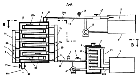
Fig. 1 is a schematic of the system, according to the invention, showing:
a- refrigerator ( 1 ) connected to the cooling-element (23 ) of the cooling-
tank
(3) by the refrigerator-pipe (15) and the refrigerator-return-pipe (15a);
b- cross-sectional view of the cooling-tank (3) showing its whole cooling-
element (23);
c- cooling-fluid-pump (4) connected to the cooling-tank (3); pressure-control
valve (6) and pressure-gauge (7) connected to the cooling-fluid pipe (5)
d- cross-sectional view of the heat-exchanger (12) with its cooling-plates (8)
connected to the cooling-fluid distributor (5a) through the connectors (5b).
e- Drilling-mud storage-tank (9) filled with drilling-mud (10);
f Drilling-mud pump (24) connected to the storage-tank (9);
g- Drilling-mud pressure-valve (13) combined with the pressure-gauge (14)
mounted on the Drilling-mud pipe (10a) which is connected to the heat-
exchanger inlet (1?);
Fig. 2 is a top view schematic of the system, without the drilling-mud
throughput
system, showing also the cooling-fluid-return-pipe (22) connected to the
cooling-tank
2 0 (3) and the heat-exchanger (12).
Fig. 3 is top cross-sectional view (C-C) of one of the cooling-plates (8) with
its two
cross-sectional views (D-D and E-E) showing the flow-dividers (21) inside the
said
cooling-plate (8).
2

CA 02377424 2002-03-28
A- Cooling aggregate
The cooling aggregate consists of
a- The refrigerator (1) connected to the cooling-element (23) of the cooling-
tank
(3) which is filled with cooling-fluid (2).
b- The circulating-pump (4), connected to the cooling tank (3), pumping the
cooling-fluid (2/2a) through the cooling-fluid-pipe (5) and passing through
the
heat-exchanger cooling-plates (8) which is prepared with flow dividers (21)
to evenly direct the cooling-fluid (2b) throughout the said cooling-plate (8).
The cooling-fluid (2c) is then returned back into the cooling-tank (3) through
the cooling-fluid return-pipe (22);
c- The pressure-valve (6) combined with the pressure-gauge (7), both placed at
the cooling-pipe {5), to regulate the cooling-fluid pressure, read on the
pressure-gauge (7).
B- Drilling-mud Throughput S, s~ tem
Tl~e drilling-mud throughput system consists of
a- The storage-tank (9), filled with drilling-mud (10), connected to the
drilling-
mud pump (11) for passing the drilling-mud (10a) through the mud-pipe (16)
into ,the heat-exchanger {12), over its cooling-plates (8), and discharging
the
cooled drilling-mud (10c) through the outlet (20).
b- The pressure control-valve (13) and the pressure-gauge (14) placed on the
mud-pipe ( 16) to control the drilling-mud pressure.
D- Heat-Exchanger part
The heat-exchanger (12) is used for the exchange of the drilling-mud heat and
3

CA 02377424 2002-03-28
consists of a number of cooling-plates (8) where the cooling-fluid is re-
circulated. These cooling plates (8) are fed by the two distributors (5a)
through
connectors (5b). The drilling-mud pipe (16) is connected to the inlet (17) of
the
heat-exchanger {12). The outlet (20) ofthe heat-exchanger (12) is prepared
with
a flow-control-valve {19) to control the flow and the residency time of the
drilling-mud (10b) in the heat-exchanger (12). The cooling-plates (8) are
prepared with flow-dividers (21) to evenly distribute the cooling-fluid (2b)
throughout the inside areas of the said cooling-plates (8).
Process Descr~tion:
The cooling-fluid (2), cooled in the cooling-tank {3) through the cooling-
element (23)
connected to the refrigerator (1), is pumped by the drilling-fluid pump (4)
and passed
through the cooling-pipe (5) and the two distributors (5a) into the heat-
exchanger
cooling-plates (8) of the heat-exchanger (12) by the connectors (5b). The
pressure
valve (6) regulates the pressure reading on pressure gauge (7). After the
cooling-fluid
(2b) is circulated through the cooling-plates (8), thereby cooling the
surfaces of these
plates, the cooling-fluid (2c) is then returned, through the cooling-fluid
return-pipe
(22), to the cooling-tank (3) for re-circulation.
The drilling-mud (10) from storage tank (9) is pumped by the drilling-mud pump
{11)
into the heat-exchanger inlet {17) passing the drilling-mud (10b) over the
cooling
2 0 Plates (8) of the heat-exchanger ( 12) and thereby reducing its high
temperature,
adjusting it to the required drilling operating temperature. The cooled
drilling-mud
{10c) is then returned back to the drilling operation. The drilling-mud
circulating
pressure, read from the pressure gauge (14), is regulated by the valve (13).
4
Representative Drawing
A single figure which represents the drawing illustrating the invention.
Administrative Status

For a clearer understanding of the status of the application/patent presented on this page, the site Disclaimer , as well as the definitions for Patent , Administrative Status , Maintenance Fee  and Payment History  should be consulted.

Administrative Status

Title Date
Forecasted Issue Date Unavailable
(22) Filed 2002-03-28
(41) Open to Public Inspection 2003-09-28
Dead Application 2005-03-29

Abandonment History

Abandonment Date Reason Reinstatement Date
2004-03-29 FAILURE TO PAY APPLICATION MAINTENANCE FEE

Payment History

Fee Type Anniversary Year Due Date Amount Paid Paid Date
Application Fee $150.00 2002-03-28
Owners on Record

Note: Records showing the ownership history in alphabetical order.

Current Owners on Record
KHADEM, FEREIDOUN
Past Owners on Record
None
Past Owners that do not appear in the "Owners on Record" listing will appear in other documentation within the application.
Documents

To view selected files, please enter reCAPTCHA code :


To view images, click a link in the Document Description column. To download the documents, select one or more checkboxes in the first column and then click the "Download Selected in PDF format (Zip Archive)" or the "Download Selected as Single PDF" button.

List of published and non-published patent-specific documents on the CPD .

If you have any difficulty accessing content, you can call the Client Service Centre at 1-866-997-1936 or send them an e-mail at CIPO Client Service Centre.


Document
Description 
Date
(yyyy-mm-dd) 
Number of pages   Size of Image (KB) 
Representative Drawing 2002-06-19 1 15
Cover Page 2003-09-03 1 48
Abstract 2002-03-28 1 35
Description 2002-03-28 4 172
Claims 2002-03-28 3 88
Drawings 2002-03-28 1 33
Correspondence 2002-04-22 1 9
Assignment 2002-03-28 2 112
Correspondence 2002-04-10 10 355