Note: Descriptions are shown in the official language in which they were submitted.
CA 02377587 2001-12-18
WO 01/81683 PCT/CA01/00526
-1-
TRANSPORTABLE UNIT FOR EARTHWORKING IMPLEMENTS
TOOL CADDY
FIELD OF THE INVENTION
This invention relates to a method for transporting loose equipment such as
augers, buckets and other equipment for construction or the like. The
invention also
relates to a unit which is transportable by trailer or truck for carrying such
equipment.
More particularly, this invention relates, in one aspect, to a transportable
unit
which may be mounted onto flatbed trailers to enable transportation of
equipment
and apparatus from a first location to a second remote location. In another
embodiment of this aspect, this invention also relates to a trailer having or
incorporating a transportable unit capable of transporting equipment from a
first
location such as a storage location, to a second location where such equipment
may
be used temporarily.
In another aspect, this invention relates to a method of transporting
equipment
from a first location, such as a storage location for the equipment, to a
second
location at which the equipment is to be used.
BACKGROUND OF THE INVENTION
Where equipment is required to be moved from one location to another,
specialized trucks or hauling equipment are often employed for the purpose of
transporting such equipment from, for example, a storage location to a site
where the
equipment is to be used. After usage, the equipment is normally returned to a
storage site or transported to another use site. Typically, it is desired to
haul
equipment such as augers, backhoe buckets, machine-operated brushes, hand
tools
such as shovels, forklift fork members and potentially a variety of other
equipment.
Typical building and construction contractors must load a variety of equipment
on
board at the start of each work day to be able to respond to expected and
unexpected work requirements.
CA 02377587 2001-12-18
WO 01/81683 PCT/CA01/00526
-2-
For contractors in the building and construction industry, the use of
specialized equipment such as specialized trailers is a relatively costly
expedient to
move equipment from one job site to another, or from the contractors place of
business to a job site. Specialized trailers can be built for hauling
particular items
of equipment, such as that used for diggers, Bobcats (tm), back-hoes, etc. The
trailer can either be specially configured (structured) to carry that
particular type of
equipment or, the equipment may be merely loaded onto a flatbed type trailer
and
secured by appropriate means to the trailer. Trailers which are specially
configured
for certain types of equipment are normally custom manufactured and are
relatively
expensive. On one hand, they have the advantage of the trailer being
specifically
configured to load and haul the equipment but on the other hand, they are
restrictive
for multi-use purposes when different types of equipment may be required to be
transported from one site to another. Such custom built equipment has also the
disadvantage that it basically can only be used for a single purpose-i.e.
haulage of
specific equipment for which the trailer was designed for.
Conventional flatbed trailers, on the other hand, merely consist of a wheeled
trailer body and as the term implies, a bed for the trailer which is generally
planar in
nature. When equipment is required to be transported, it is merely loaded onto
the
bed, and secured by appropriate restraining means such as rope, chain or the
like.
Although more economical than a custom built trailer, these multi-use flatbed
trailers
have a restriction in the sense that individual pieces of equipment must be
located
in a random fashion and secured by suitable means. Such trailers, which are
usual
in the transportation industry for hauling equipment, normally only have a
single flat
bed surtace. As such, carrying capacity is somewhat limited relative to a
multi-
platform trailer. Conventional flatbed trucks are also able to carry only a
limited
number of tools when the tools are simply placed willy-nilly on the bed. This
is a
particular restriction on contractors who work on several job sites over the
course of
the day, and often do not even know at the beginning of the day what tools
they will
need. For these workers, it is desirable to provide a means to conveniently
carry a
CA 02377587 2001-12-18
WO 01/81683 PCT/CA01/00526
-3-
full complement of tools and small loose equipment on a conventional flatbed
truck,
while still leaving room for a Bobcat (tm) or other small power shovel or the
like.
SUMMARY OF THE INVENTION
The present invention is directed to employment of conventional trailer units
in which the trailer may mount a one piece transportation assembly for
transporting
equipment. The transportation assembly, including ail tools carried by the
assembly,
can be readily and easily mounted on and removed from the bed of such a
conventional trailer unit. In one aspect, the invention is a one piece
transportation
unit of the type which is adapted for mounting on a conventional trailer bed
to permit
transportation of equipment and implements comprising a monolithic frame. The
invention is characterized by the frame comprising spaced apart upper and
lower
equipment mounting surfaces. The frame has pairs of opposed sides, one pair of
sides defining lateral sides for the unit, the other pair forming front and
back sides.
The frame has supporting members for positioning the upper surface in a spaced
apart relationship relative to the lower surface. At least one side of the
pairs of sides
has an access opening between the upper and lower surfaces to permit loading
of
equipment onto the upper or lower surfaces. A plurality of spaced apart
implement
retainers is supported by and mounted to the frame members.
Desirably, the supporting members comprise a plurality of vertical frame
members. The frame also has horizontal frame members and at least some of the
spaced apart implement retainers are mounted by at least one of the vertical
or
horizontal frame members between the upper and lower surfaces. In another
preferred embodiment, the unit includes at least two load supporting surfaces
in an
upper and lower planar relationship, the upper surface being spaced from the
lower
surface by a distance sufficient to permit loading of transportable apparatus
on the
lowermost surface.
CA 02377587 2001-12-18
WO 01/81683 PCT/CA01/00526
-4-
In other preferred embodiments, the upper surface is mounted in a spaced
apart relationship to the lower surtace by a plurality of peripheral spaced
apart frame
members, the upper surface having substantially open lateral sides whereby
transportable apparatus may be loaded on at least the upper surface.
Preferably
each of the surfaces includes retaining means for releasably retaining
transportable
equipment mounted on the surfaces.
The unit preferably includes a plurality of tool carriers specifically adapted
to
carry a particular tool. These include troughs to carry augers, platforms
shaped to
carry a specific size of bucket and tubes for holding brooms, forklift fork
tines or
other tools. Specific fasteners may be provided to hold the implements within
the
carriers, such as turnbuckle cables to hold forklift fork tines which may
fasten to the
truck bed.
Desirably, in this embodiment of the invention, the implement retainers
comprise a plurality of retaining means mounted in spaced apart relationship
on said
unit, each retainer means being adapted to retain separate implements. These
can
include retainers specifically adapted to hold augers, fork lift members,
buckets and
brooms. The implement retainers may comprise elongated mounting plates
angularly displaced relative to the plane of the lower platform.
In another preferred embodiment of the invention, the unit includes means for
releasably securing the unit to a trailer. The upper surface may also comprise
a
plurality of horizontal longitudinal and transverse frame members forming an
upper
open supporting surface. Preferably the lower surface comprises a plurality of
horizontal positioned longitudinal and transverse frame members forming a
lower
open supporting surface.
CA 02377587 2001-12-18
WO 01/81683 PCT/CA01/00526
-5-
Another embodiment of the invention comprises in combination a trailer
assembly comprising a wheeled trailer together with a transportable equipment
caddy as described above.
A still further embodiment of the invention is a method of transporting
equipment from a storage site to a remote location, comprising in general the
steps
of (1 ) providing a transportation unit as characterized above mountable on a
conventional trailer bed, (2) mounting and securing of the unit on a wheeled
trailer
bed at the first site, (3) loading equipment onto at least one of the upper
and lower
mounting surfaces either before or after the unit is mounted on the trailer
bed, and
(4) transporting the equipment on the unit to the remote location.
In a further aspect, the unit is mounted onto a trailer bed by means of a fork
lift which is then carried to the remote location. In a still further aspect,
each tool
carried by the unit is placed within an individual trough, carrier or retainer
specifically
shaped to hold the tool. At least some of the tools are retained during
carriage by
tiedowns or other fastening means.
Having thus generally described the invention, reference will now be made
to preferred embodiments described by reference to the accompanying drawings.
BRIEF DESCRIPTION OF THE DRAWINGS
Figure 1 is a perspective view of a unit according to the present invention
for
mounting on a trailer;
Figure 2 is a view similar to Figure 1 but showing the unit having implements
(in dotted lines) or accessories mounted on the unit for transportation to a
work site;
Figure 3 is a top plan view of the unit of Figure 2 showing the accessories in
dotted lines;
CA 02377587 2001-12-18
WO 01/81683 PCT/CA01/00526
-6-
Figure 4 is a plan view of a typical retaining means for implements which is
mounted on or within the unit of Figure 1;
Figure 5 is a side elevational view of another type of retaining means;
Figure 6 is a side elevational view showing another type of retaining means
otherwise illustrated in Figure 1;
Figure 7 is a side elevational view of adjustable mounting means for retaining
components or implements in place on the platform;
Figure 8 is a view similar to view 7 but showing another type of adjustable
mounting means;
Figure 9 is a perspective view of a further embodiment of the invention;
Figure 10 is a perspective view of the embodiment shown in Figure 9, with a
further implement attachment mounted thereto; and
Figure 11 is a perspective view of a portion of the apparatus shown in Figures
9 and 10, namely a tool retainer.
DETAILED DESCRIPTION OF THE PREFERRED EMBODIMENTS
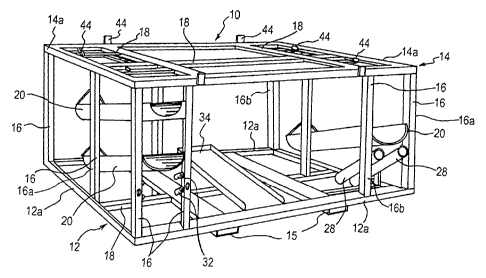
Referring initially to Figure 1, a unit 10 for transporting equipment and or
implements, includes a generally horizontal lower frame 12 of a rectangular
configuration. Frame 12 is made up of a plurality of metal outer frame members
12a.
A horizontal upper frame 14 is made up of a plurality of metal outer frame
members
14a. The upper and lower frames 12 and 14 are mounted in a spaced apart manner
by a plurality of vertical frame members 16 with all of the frame members 12a,
14a
and 16 forming a monolithic unit. Depending on the size and weight of the unit
and
CA 02377587 2001-12-18
WO 01/81683 PCT/CA01/00526
_'7_
the material of which the unit is constructed of, a pair of supporting beams
15 may
also be employed ( if required). Conveniently, the frame members comprise
hollow
steel frame members having a rectangular section. The vertical members define
a
pair of opposed lateral sides 16a and front and back sides 16b.
The upper and lower frames 12 and 14 each form a platform. Typically,
further frame members extending in a longitudinal or transverse direction may
be
employed to complete each platform. As indicated in Figure 1, such additional
longitudinal and transverse frame members are indicated by a common reference
numeral 18, the number and orientation of which will vary depending on the
desired
configuration for the unit. It will be understood that various modifications
and
alternatives can be employed to form the upper and lower platforms. The
drawings
illustrate an open lattice type arrangement; obviously, closed upper and/or
lower
platforms may be employed or various combinations of partially open and
partially
closed structures may be employed within the scope of this invention.
One feature of the present invention is that equipment of various sizes and
dimensions can be loaded onto the lower platform. To this end, it will be seen
from
Figure 1 that access to the interior space between the upper and lower
platforms is
achieved by providing a large open area between adjacent supporting frame
members so that ready access can be had to the lower platform for loading and
unloading different types of equipment. Generally speaking, the upper platform
does
not require any supporting or containing framework other than the frame
structure
forming the upper platform per se. Thus, in the embodiment shown, all sides of
the
upper platform are free from extraneous supports so that loading of the upper
platform can be carried out from any side.
The portable unit can be designed to carry specific types of implements or
tools. For this purpose, the unit may contain retaining means for such
implements
or tools. As illustrated in Figures 1 and 4, retaining means for augers
comprise
CA 02377587 2001-12-18
WO 01/81683 PCT/CA01/00526
_g_
angularly mounted troughs 20 which are secured to adjacent frame members 16 at
one or more places by suitable means such as welding, bolts or the like. The
angular mounting of the troughs 20, where the troughs are located adjacent the
sides of the unit, permits easy loading and discharge of implements retained
by the
troughs while preventing such implements from being accidentally discharged
during
transportation of the unit on a trailer. As shown in Figure 4, the retaining
means
retaining an auger 22 may include means for positioning the auger on the
trough 20
such as a closure member 24 for the trough and/or a wire frame member 26 to
prevent the auger from being accidentally discharged from the interior side of
the
trough.
Other implement retaining members are illustrated in Figures 5 and 6, as well
as Figure 1. Different configurations of the retainer members include tubular
members 28 for holding rods, brooms, hand tools and the like. The retainer
members 28 are angularly mounted and may utilize closed ends to hold the
implements. Smaller tubular retainers 28 and 32 (Figures 5 and 6) can also be
employed. These may retain other types of tools or even pins and bolts.
Returning to Figure 1, where the trailer mountable unit is adapted to
transport
implements such as buckets, drills or the like for equipment such as back-
hoes,
bobcats or the like, the upper and/or lower platforms may include additional
retainers
such as trough shaped retainer 34 for larger components. The shape and size of
these retainers will of course vary depending on the particular implement to
be
retained.
Larger components or implements, such as buckets can be stored both on the
lower and upper platforms for transport. The upper platform, as illustrated in
Figure
2, shows mounting of two such buckets indicated by dotted lines 40, while the
lower
platform mounts a further bucket 42. To position and retain the buckets in
place
during transport, particularly where the same implements are being transported
by
CA 02377587 2001-12-18
WO 01/81683 PCT/CA01/00526
-9-
the same transportation unit, either fixed or movable stops or holders can be
employed. One version of these can be seen from Figures 1 and 2 where fixed
plates 44 can be secured by welding or the like to the frame members. These
plates
44 not only retain the buckets, but also position them on the upper and/or
lower
platform.
Such stops or holders can also be adjustable as shown in Figures 7 and 8.
Various types of brackets 50 can be employed which can be positioned at
different
locations on the platform. Removable pins 52 can be inserted through apertures
in
the brackets and into holes 54 of the various frame members to provide
adjustment.
Referring to Figure 2, it will be seen that the mobile unit of the present
invention can be mounted on a trailer 58. The trailer can be a suitable
flatbed trailer
having a planar base 60 with wheels 62. Once loaded onto the trailer 58, the
unit
may be releasably secured to truck bed rails 64 by means of turnbuckle straps
or
cables 66 or the like. Additional turnbuckle cables or straps 67 fasten fork
tines,
from a forklift, within the unit 10 via attachment to the rails 64.
A further embodiment of the invention is illustrated at Figures 9 through 11.
In this version, the frame 12 has mounted to its upper corners D rings 70, for
fastening straps 72 for tying the apparatus to a truck or trailer. A cup-
shaped holder
74 welded to one of the vertical supports 16 holds a removable open-ended pipe
76.
The pipe 74 comprises a snipe for tightening of load binders for chaining down
heavy equipment and machinery to the apparatus. A pair of straps 78 are
provided,
~5 first strap 78(a) spanning the upper deck and a second strap 78(b) spanning
two
vertical members 16. The straps 78(a) are tightened by winches 80. The front
strap
78(b) is for holding large pallet forks in place within the interior of the
framework 12.
The upper straps 78(a) may be used to secure attachments to the top deck.
CA 02377587 2001-12-18
WO 01/81683 PCT/CA01/00526
-10-
The embodiment of Figures 9 through 11 also includes various modifications
to the tool holders. In particular, the lower trough-shaped retainer 34'
includes a flat
floor 85 and a pair of walls which converge towards the rear end of the
retainer. The
walls 82 assist in supporting various attachments. Rear walls 87 may extend
above
the side walls to act as a stop for retained implements. Rear posts 89 elevate
the
rear end of the retainer 34'.
The U-shaped auger troughs 20' include a modified rear stop member 84,
having an inverted U-shape.
0
A further modification consists of a removable trough 86, shown in dotted
lines in Figure 9 and Figure 10. The trough 86 has a broad U-shaped cross-
sectional profile and is removably bolted to the top deck of the framework 12.
The
trough 86 is particularly suited for cradling sweeper brushes and snow blades.
5
A wide variety of implements may be carried by the device, including without
limitation skid steer buckets, auger drives, hydraulic jack hammers, padfoot
and
smoothing vibrating compactors, soil tillers, landscape rakes, bush mowers,
sweepr
clean up buckets, angle brooms, snow dozer blades, auger bits, auger
extensions,
pallet forks, tree spades and various hand tools.