Note: Descriptions are shown in the official language in which they were submitted.
CA 02377716 2005-05-11
64536-1054
1
ARTICLE WITH IMPROVED TAMPER EVIDENCE
Field Of The Invention
The present invention relates to articles, more
particularly to tamper evident containers such as tamper
evident envelopes, characterized by improved evidence of
tampering.
Background Of The Invention
It is known that banking establishments and the
like use tamper evident containers for transmitting
valuables, for example specified sums of money, securities,
cash in transit (CIT), etc. from one department to another.
The system operated by such establishments is such that it
is readily possible to ascertain whether a tamper evident
container has been stolen in transit. However it is
ordinarily more difficult to ascertain whether the tamper
evident container has been opened in transit and then
resealed after some of the contents have been removed. In
order to overcome this problem, tamper evident containers
have been provided wherein any attempt to gain access to the
interior of the tamper evident container becomes visibly
apparent.
Typically, the walls of such tamper evident
containers are formed of sheet material including a portion
having an opening which gives access to the interior of the
tamper evident container. The tamper evident containers
include a closure portion arranged to be superposed on the
portion having the opening, to close the tamper evident
container. Closure is effected by means of a band of high-
tack adhesive which is applied across the closure portion or
the portion having the opening, for example from the molten
state, from transfer tape, solvent cast or in the form of a
CA 02377716 2005-05-11
64536-1054
2
tape. The adhesive may be pressure sensitive adhesive, and
suitable adhesives include thermoplastic hot melt adhesives,
silicone adhesives, acrylic pressure sensitive adhesives,
solvent cast adhesives, W (ultraviolet) or EB (electron
beam) cured acrylic adhesives, and the like.
Such adhesives are required to have high initial
tack with respect to the surface of the sheet material and
also to have high adhesive and cohesive strength. In order
to provide a visible indication of any attempt to open the
tamper evident container by separating the closure portion
and the portion having the opening, the adhesive should be
strong enough to cause stretching, tearing, or other
mechanical distortion of the portions upon attempted opening
of the container. If desired, perforations or serrated edges
may be provided in the closure portion to indicate tearing
and emphasize the effect.
With the exception of silicone adhesives,
adhesives suitable for the closure of tamper evident
containers have a softening temperature which is below the
melting point of the closure portion and of the sheet
material. The softening temperature is commonly in the range
of between 50°C and 90°C. Accordingly, by the local
application of heat, an unauthorized person can open and
reseal the tamper evident container without any visible
indication that the tamper evident container has been
opened.
To discourage this practice, thermochromic inks
have been used in tamper evident containers. These inks are
formulated to develop a permanent, non-reversible, and
visibly evident color change when the adhesive on the
envelope is exposed to heating. In this way, if unauthorized
access to e.g. a tamper evident container is attempted by
CA 02377716 2005-05-11
. 64536-1054
3
means of local application of heat to an adhesive on the
envelope, a color change in the ink makes this evident.
Typical conventional thermochromic inks for this application
are formulated from a leuco dye, a phenolic compound, an
organic diluent, water, and polyvinyl alcohol. A
thermochromic ink composition with improved wet abrasion
resistance includes, in addition to the basic formulation of
conventional inks, hydrolyzed polyvinyl acetate) and an
organic compound with at least one carbonyl group,
preferably an aldehyde and more preferably a dialdehyde such
as glyoxal. This improved ink composition is disclosed in
published PCT application WO 01/04221 published on
January 12, 2001.
Although these thermochromic ink systems provide a
good visual indication of unauthorized tampering with the
tamper evident container or other article, they typically
require the end user to know in advance about the change in
color; otherwise, the color change triggered by subsequent
tampering activity may go unnoticed.
Also, such ink systems can be circumvented by
unauthorized personnel by removing the thermochromic ink
coating with an organic or aqueous solvent. To prevent this,
further protection must be provided by printing messages
over the thermochromic ink layer or coating, to prevent or
make obvious any tampering of the thermochromic ink layer
itself prior to heating.
It is therefore desirable to provide an article,
especially an article such as a tamper evident container
which utilizes thermochromic ink, which offers improved
evidence of tampering.
CA 02377716 2005-05-11
64536-1054
3a
Summary Of The Invention
According to a broad aspect of the present
invention there is provided a tamper evident container
comprising: a) a first portion; b) an opening capable of
providing access to the interior of the tamper evident
container; c) a closure portion arranged to be superposable
with the first portion; d) an adhesive, applied to the first
portion or closure portion, having a free surface so
arranged as to seal the opening on superposition of the
first portion and the closure portion; and e) an indicator
which is capable of displaying a message, wherein the
indicator is disposed, on superposition of the first portion
and the closure portion, adjacent to the opening, and
wherein the indicator comprises (i) a first layer comprising
a thermochromic ink composition, and (ii) a second layer,
disposed on or adjacent the first layer, comprising a
composition different from the ink composition of the first
layer and selected from the group consisting of: (a)
thermochromic ink; (b) aqueous evident ink; (c) mechanical
evident ink; (d) solvent evident ink; and (e) deactivating
agent.
All compositional percentages used herein are
presented on a "by weight" basis, unless designated
otherwise.
CA 02377716 2002-O1-02
WO 01/04014 PCT/US00/17552
4
Definitions
"Aqueous evident" herein refers to a continuous or discontinuous layer,
coating,
printing, or messaging that displays a visual change in color, shape, size, or
pattern when
contacted with an aqueous medium.
"Container" herein refers to bags, pouches, envelopes, or other articles which
can
store a product.
"Deactivating agent" herein refers to a chemical agent that prevents
thermochromic
ink, covered by the agent, from changing color upon heating to the normal
activation tem-
perature of the ink.
"Mechanical evident" herein refers to a continuous or discontinuous layer or
layers,
coating, printing, or messaging that displays a visual change in color, shape,
size, or pattern
when stretched, torn, or otherwise distorted, or when an attempt is made to
open a container
which includes the mechanical evident layer.
"Message" herein refers to any alphabetic, numeric, or alphanumeric message,
warning, or statement; a design; a pattern; a logo; change in color, design,
or pattern; or other
indicia that communicates to the viewer that tampering has occurred or been
attempted.
"Solvent evident" refers to a continuous or discontinuous layer, coating,
printing, or
messaging that displays a visual change in color, shape, size, or pattern when
contacted with
a solvent.
"Thermochromic" herein refers to an ink that exhibits a permanent, non-
reversible,
and visibly evident color change when exposed to heat.
Brief Description Of The Drawings
A detailed description of preferred embodiments of the invention follows, with
reference to the attached drawings, wherein:
FIG. 1 is a diagrammatic front view of an open tamper evident container in ac-
cordance with a first embodiment of the present invention;
Figure 2a is a diagrammatic section through a part of the tamper evident con-
tamer of Figure 1 on an increased scale when the tamper evident container is
open;
Figure 2b is a diagrammatic section through a part of the tamper evident con-
tamer of Figure 1 when the tamper evident container is closed;
Figure 3a and 3b are respectively diagrammatic sections through a variation of
the tamper evident container of the embodiment of Figure 1 when open and
closed;
Figure 4 is a diagrammatic section through a part of a tamper evident
container
of a second embodiment of the invention;
CA 02377716 2002-O1-02
WO 01/04014 PCT/US00/17552
Figure 5 is a diagrammatic section through a variation of the tamper evident
container of Figure 4 showing optional additional security features;
Figure 6 is a diagrammatic section through a precursor of a tamper evident
container
of the first embodiment of the invention when the tamper evident container is
open, during an
5 exemplary production process;
Figure 7 is a diagrammatic section through a tamper evident container of a
third em-
bodiment of the invention;
Figure 8 is a diagrammatic section through a tape of a fourth embodiment of
the in-
vention;
Figure 9 is a diagrammatic section through a tape of a fifth embodiment of the
in-
vention;
Figure 10 is a diagrammatic section through a tamper evident container of a
sixth
embodiment of the invention;
Figure 11 is an enlarged view of a portion of Figure 7;
Figure 12 is an enlarged view of a portion of Figure 10;
Figure 13 is a diagrammatic section through a tape of a seventh embodiment of
the
invention;
Figure 14 is a diagrammatic section through a tape of an eighth embodiment of
the
invention;
Figure 15 is a diagrammatic section through a tape of a ninth embodiment of
the in-
vention;
Figure 16 is a diagrammatic section through a tape of a tenth embodiment of
the in-
vention;
Figure 17 is a diagrammatic section through a tape of an eleventh embodiment
of the
invention;
Figure 18 is a diagrammatic section through a tape of a twelfth embodiment of
the
invention;
Figure 19 is a diagrammatic section through a tape of a thirteenth embodiment
of the
invention;
Figure 20 is a diagrammatic section through a tape of a fourteenth embodiment
of the
invention;
Figure 21 is a plan schematic view of a printed, corona treated, and
overcoated film
of the invention;
Figure 22 is a side schematic view of the printed, corona treated, and
overcoated film
of Figure 21;
CA 02377716 2005-05-11
. 64536-1054
6
Figure 23 is a side schematic view of a printed,
corona treated film having a thermochromic ink layer, and an
aqueous sensitive ink layer as a top layer;
Figure 24 is a side schematic view of a printed,
corona treated film having an aqueous sensitive layer, and a
thermochromic ink layer;
Figure 25 is a side schematic view of a printed
film according to an alternative embodiment of the
invention;
Figure 26 is a side schematic view of a printed
film according to an alternative embodiment of the
invention; and
Figure 27 is a perspective view of a printed film
approximately according to the embodiment of Figure 26.
Detailed Description Of The Invention
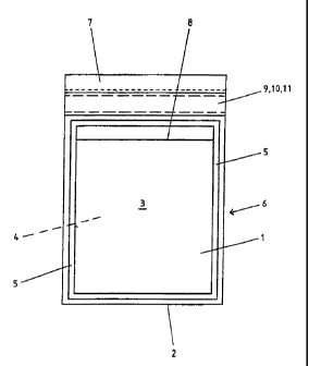
Referring to Figures 1, 2a and 2b, the tamper
evident container is preferably formed from a single strip 1
of flexible thermoplastic sheet material. This sheet
material can comprise any suitable material, preferably high
density polyethylene, low density polyethylene, a blend of
high density polyethylene and low density polyethylene, high
density polyethylene with a filler, cellulose acetate,
polyester, or polypropylene. For the sake of clarity, the
sheet material is illustrated herein as a monolayer film.
However, those skilled in the art will understand that
multilayer films can also be beneficially used in connection
with tamper evident containers. An example is a film with a
polymeric core or inner layer, and two outside layers of
high density polyethylene. The sheet material is folded
laterally along a fold line 2 to form a first portion 3 and
CA 02377716 2005-05-11
. 64536-1054
7
a second portion 4. The thermoplastic sheet material is
preferably transparent, partially transparent or
translucent, or a combination of opaque and transparent so
as to make it easier to see evidence of tampering. The
folded portions 3 and 4 are heat welded to each other in a
zone 5 which extends parallel with and close to each of the
longitudinal and each of the lateral edges of the portions
to produce a tamper evident container 6 wherein the second
portion 4 is longer than the first portion 3. The second
portion 4 has a closure portion in the form of a flap 7. The
flap portion 7 is preferably at least translucent, and more
preferably is transparent.
At an end region of the tamper evident container 6
closer to the flap portion 7, an opening line in the form of
a slit 8 extends across the first portion 3 terminating at
each end at the weld zone 5. The slit 8 provides access to
the interior of the tamper evident container 6. A band of
adhesive 9 is provided on the flap portion 7. The choice of
adhesive is not limited, although the adhesive should be a
high tack adhesive having high cohesive and adhesive
strength, such that any attempt to open the tamper evident
container by separating the first portion and the closure
portion will result in stretching, tearing, or other
distortion of the first and/or closure portions, and can
include any or all of those adhesives mentioned above. The
adhesive 9 may be applied from the molten state or in the
form of a tape, or by any other suitable method such as
solvent cast or transfer tape technique. As can be seen from
Figure 2a, a releasable cover strip 10 is preferably
provided to cover the free surface of the adhesive 9 when
the tamper evident container is open.
As can be seen especially in Figure 2a, an
indicator 11, comprising a first, thermochromic ink
CA 02377716 2005-08-16
64536-1054
7a
composition, and a second ink composition disposed over and
different from the first, thermochromic ink composition, is
provided on the flap portion 7 and is covered by the
adhesive 9. The indicator is visible through the flap
portion 7. The second ink composition can be a thermochromic
ink composition different compositionally from the first
thermochromic ink composition; a mechanical evident ink
composition; or a combination of these.
When using the tamper evident container, the items
to be held in the tamper evident container are introduced
through the slit 8. The cover strip 10 is then removed from
the adhesive 9 and the flap portion 7 is folded over onto
the portion 3, with the fold line being close to the
proximal laterally extending part of the weld zone 5. The
disposition of the adhesive layer 9 relative to the fold
line of the flap portion 7 is such that when the flap
portion 7 is brought down onto the first portion 3, the part
of the flap portion 7 carrying the adhesive 9 straddles the
slit 8 so that the slit 8 is completely overlain by the said
adhesive 9. Thus, the slit 8 is completely sealed and there
is no access opening whatsoever to the interior of the
tamper evident container 6 (see Figure 2b). Preferably, the
parts of the first portion 3 adjacent to the slit 8 have
previously been subjected to a surface treatment such as
corona discharge to assist adhesion of the adhesive to the
substrate. The indicator 11 overlies at least that part of
the portion 3 adjacent to the slit 8 which is distant from
the lateral weld zone 5a. If desired, the flap portion 7 may
include a receipt portion 12 which is detachable by means of
perforations 13.
Referring to Figures 3a and 3b, in which parts
corresponding to those of Figures l, 2a and 2b are indicated
by like reference numerals, it will be seen that the
CA 02377716 2005-08-16
64536-1054
7b
indicator 11 can also be provided on at least that part of
the portion 3 which is immediately adjacent the opening 8
distant from the lateral weld zone 5a. After closure of the
tamper evident container, the adhesive 9 completely overlies
the opening slit 8 and the indicator 11. In this embodiment,
the
CA 02377716 2002-O1-02
WO 01/04014 PCT/US00/17552
8
adhesive 9 must be translucent, or preferably transparent, to ensure that the
indicator 11 is
visible through the flap portion 7.
Referring to Figure 4, in which parts corresponding to parts in Figures 1 to
3b have
the same reference numerals, the tamper evident container 66, which is shown
in the open
state, can be sealed by a closure member 14. The closure member 14 comprises a
thermo-
plastic substrate 15 which is at least translucent and preferably is
transparent and which is
adhered to at least a part of the section 16 of the first portion 3 along the
whole lateral width
of the tamper evident container, and optionally to the second portion 4, by an
adhesive layer
9. A releasable cover strip 10 prevents adhesion of the closure member 15 to
the first portion
3 adjacent to the opening 8 prior to the filling of the tamper evident
container. In use, the
items to be held in the tamper evident container are introduced through the
slit 8, the cover
strip 10 is removed, and the closure member 14 seals the opening 8 by
completely overlying
the same. The free surface of the adhesive 9 which is exposed on removal of
the cover strip
10 adheres the substrate 15 to the first portion 3,16. An indicator 11 is
provided on the trans-
parent thermoplastic substrate 15 in such a position that, when the tamper
evident container is
sealed, the indicator overlies the opening 8, or at least that part of the
first portion 3 which is
adjacent to the opening 8 and distant from the lateral weld zone Sa. The
indicator 11 may
equally be applied to the adhesive 9 (by for example ink jet printing) or to
the part of the first
portion 3 adjacent the slit opening 8 and distant from the weld zone Sa.
Further security features may be incorporated into the tamper evident
containers as is
particularly illustrated in Figure 5, which is a variation of the embodiment
of Figure 4. These
security features can also be incorporated into the embodiments of Figures 1
to 3. In Figure
5, the closure member 14 comprises a transparent thermoplastic substrate 15
which carries a
discontinuous weakly bonded adhesive layer 17 such as ethyl cellulose and a
strongly bonded
adhesive layer 18 such as epoxy cellulose acetate propionate. Because of the
layers 17 and
18, any attempt to gain access to the interior of the tamper evident container
6 by lifting the
substrate 15 will result in those parts of the layer 18 which are in registry
with layer 17 re-
maining adhered to portions 3 and 4 whilst other parts of the layer I 8 will
remain adhered to
substrate 15. This results in the formation of a visible pattern constituted
by the split layer 18
which pattern cannot be obliterated by re-sealing the closure member. Soluble
transparent or
translucent dye may be carried in a layer 19. Layer 20 comprises a high tack
adhesive in
which the indicator 11 is disposed. It is not essential, however, for the
indicator 11 to be dis-
posed in the layer 20. Layer 21 is an optional second layer of adhesive which
carries optional
ink jet printing 22.
CA 02377716 2005-05-11
64536-1054
9
Referring now to Figure 6, the tamper evident
container is produced by folding longitudinally a continuous
length 101 of thermoplastic sheet material (after it has
been optionally printed as appropriate) into a J-form where
it includes a first portion 103 folded at fold 102 so as to
be superposed on a part of a second portion 104 so as to
leave a flap portion 107 of the second portion 104 exposed.
The first portion 103 is heat sealed to the second portion
104 by a heat seal 105. Preferably, a region of the flap
portion 107, which region is generally parallel to the heat
seal 105, is subjected to a surface treatment such as corona
discharge to improve its adhesion characteristics in that
region. A band of high-tack adhesive 109 is applied to that
region and is covered by a removable cover strip 110
optionally after having been provided with a security code
by means of an ink jet printing technique. An indicator 111
can be applied to the flap portion 107 prior to the
application of the adhesive 109. Alternatively, the
indicator may be applied generally at region 113. The region
indicated generally by 113 may also be subjected to a
surface treatment such as corona discharge to improve its
adhesion. Slit 108 corresponds to slit 8 shown in Figures 2a
to 5.
The continuous length 101 of sheet material is
then cut transversely using a double heat sealing device
comprising two pairs of heat sealing jaws between which is
located a cutting blade so that the sheet material is cut
into adjacent transverse sections each having heat sealed
edges. Each of these sections constitutes a tamper evident
container in accordance with the invention. It will be
appreciated that a similar method can be applied for the
production of the tamper evident containers in accordance
with Figures 4 and 5. It is particularly advantageous to
CA 02377716 2005-05-11
~ 64536-1054
9a
apply the closure member as a pre-made tape which will
desirably incorporate the indicator.
Referring now to Figure 7, a tamper evident
envelope 200 includes a sheet portion 201 to which a tamper
evident tape 203, having printed or coated thereon, or
including as a layer thereof, the thermochromic ink of the
invention, is adhered by means of seal 202. Seal 202 can be
e.g. a heat seal or an adhesive seal. Adhesive 205 is
adhered to sheet portion 201, and is covered by a removable
release liner 204. Figure 11 is an enlargement of a portion
of Figure 7. In practice, after a product such as cash, a
biological specimen, or some other object is placed through
the opening 211 into the interior of container 200, the
release liner 204 is removed to expose adhesive 205. The
tamper evident tape 203 is then pressed against adhesive 205
to seal the container. If an unauthorized attempt is made to
open the container by heating the adhesive 205 of the
container to reduce the level of adhesion of adhesive 205 to
tamper evident tape 203, the tape 203 will change color.
Figure 10 illustrates an alternative embodiment. A
tamper evident container 400 includes a sheet portion 401 to
which a tamper evident tape 403, having the indicator of the
CA 02377716 2002-O1-02
WO 01/04014 PCT/US00/17552
invention, is adhered by means of seal 402. Seal 402 can be e.g. a heat seal
or an adhesive
seal. Adhesive 405 is adhered to tamper evident tape 403, and is covered by a
removable
release liner 404. Figure 12 is an enlargement of a portion of Figure 10. In
practice, after a
product such as cash, a biological specimen, or some other object is placed
through the
5 opening 411 into the interior of container 400, the release liner 404 is
removed to expose ad-
hesive 405. The tamper evident tape 403, with adhesive 405 adhered thereto, is
pressed
against sheet portion 401 to seal the container. If an unauthorized attempt is
made to open
the container by heating the adhesive 405 of the container to reduce the level
of adhesion of
adhesive 405 to sheet portion 401, the tape 403 will change color.
10 Figures 8 and 9 illustrate two embodiments for either of tamper evident
tape 203 or
403.
In Figure 8, a tape film 206 can be made of a clear or colored polymeric
material
such as a polyolefin. Adhered to a portion of tape film 206 is a layer of a
mechanical evident
message print 207. This layer has a message printed thereon, generally masked
by the tape
film 206 and/or layer 208, which becomes visible and readable in the event
someone seeks to
gain access to the contents of the container by attempting to separate tape
203 or 403 from
sheet material 201 or 401 respectively. Adhered to another portion of tape
film 206 is a layer
209 of thermochromic ink. Adhered to layer 207 is a layer 208 of an overcoat
print. This
layer, generally of a single opaque color, masks the message of the message
print layer 207
unless and until the container is opened.
In Figure 9, a tape film 306 is made of a clear or colored polymeric material
such as a
polyolefin. Adhered to one side of tape film 306 is a layer 309 of
thermochromic ink. Ad-
hered to the other side of tape film 306 is a layer of a mechanical evident
message print 307.
This layer has a message printed thereon, generally masked by the tape film
306 and/or layer
308, which becomes visible and readable in the event someone seeks to gain
access to the
contents of the container by separating adhesive 205 or 405 from sheet
material 201 or 401
respectively. Adhered to layer 307 is a layer 308 of an overcoat print. This
layer, generally
of a single opaque color, masks the message of the message print layer 307
unless and until
the container is opened.
In Figure 13, a tape film 501 is made of a clear or colored polymeric material
such as
a polyolefin. Adhered to one side of tape film 501 is a layer 502 of
thermochromic ink (indi-
cated as "T" in the drawing). Adhered to layer 502 is a layer of a mechanical
evident ink or
message print 503 (indicated as "M" in the drawing).
In Figure 14, a tape film 504 is made of a clear or colored polymeric material
such as
a polyolefin. Adhered to a portion of one side of tape film 504 is a layer 505
of thermochro-
CA 02377716 2005-05-11
64536-1054
11
mic ink (indicated as "T" in the drawing). Adhered to
another portion of one side of tape 504, and adjacent to
layer 505, is a layer 506 of a mechanical evident ink or
message print (indicated as "M" in the drawing).
In Figure 15, a tape film 507 is made of a clear
or colored polymeric material such as a polyolefin. Adhered
to one side of tape film 507 is a layer 508 of a first
thermochromic ink (indicated as "T1" in the drawing). Adhered
to layer 508 is a layer 509 of a second thermochromic ink or
message print (indicated as "T2" in the drawing).
In Figure 16, a tape film 510 is made of a clear
or colored polymeric material such as a polyolefin. Adhered
to a portion of one side of tape film 510 is a layer 511 of
a first thermochromic ink (indicated as "T1" in the drawing).
Adhered to another portion of one side of tape 510, and
adjacent to layer 511, is a layer 512 of a second
thermochromic ink or message print (indicated as "Tz" in the
drawing).
In Figure 17, a tape film 513 is made of a clear
or colored polymeric material such as a polyolefin. Adhered
to one side of tape film 513 is a layer 514 of thermochromic
ink (indicated as "T" in the drawing). Adhered to layer 514
is a layer of an aqueous evident ink or message print
(indicated as "A" in the drawing).
In Figure 18, a tape film 516 is made of a clear
or colored polymeric material such as a polyolefin. Adhered
to a portion of one side of tape film 516 is a layer 517 of
thermochromic ink (indicated as "T" in the drawing). Adhered
to another portion of one side of tape 516, and adjacent to
layer 517, is a layer 518 of an aqueous evident ink or
message print (indicated as "A" in the drawing).
CA 02377716 2005-05-11
64536-1054
lla
In Figure 19, a tape film 519 is made of a clear
or colored polymeric material such as a polyolefin. Adhered
to one side of tape film 519 is a layer 520 of thermochromic
ink (indicated as "T" in the drawing). Adhered to layer 520
is a layer 521 of a solvent evident ink or message print
(indicated as "S" in the drawing).
In Figure 20, a tape film 522 is made of a clear
or colored polymeric material such as a polyolefin. Adhered
to a portion of one side of tape film 522 is a layer 523 of
thermochromic ink (indicated as "T" in the drawing). Adhered
to another portion of one side of tape 522, and adjacent to
layer 523, is a layer 524 of a solvent evident ink or
message print (indicated as "S" in the drawing).
Referring to Figures 21 and 22, the tamper evident
tape 601 is constructed by printing a polymeric film 602,
such as a polyethylene or other polyolefinic film, with a
clear message 603. The film is transparent, translucent,
colored or white. After printing the message, the printed
film is corona treated on the printed side of tape 601. The
printed, corona treated film is then flood coated by
printing with an overcoat ink 604. The overcoat ink is a
clear or
CA 02377716 2002-O1-02
WO 01/04014 PCT/US00/17552
12
colored ink, depending on the nature of the film. The purpose of the overcoat
ink is to com-
pletely mask, i.e. make the message invisible when viewed through the film
from the side
opposite to that of printing. Additional colored inks 605 can be flood coated
onto the printed,
corona treated film by printing.
Referring to Figure 23, the tamper evident tape 611 is constructed by printing
a
polymeric film 612, such as a polyester, polyethylene or other polyolefinic
film, with a clear
message 613. The film is transparent, translucent, colored or white. After
printing the mes-
sage, the printed film is corona treated. The printed, corona treated film is
then flood coated
by printing with an overcoat thermochromic ink 614. The overcoat ink is a
clear or colored
ink, depending on the nature of the film. The purpose of the overcoat ink is
to completely
mask, i.e. make the message invisible when viewed through the film from the
side opposite to
that of printing. An aqueous sensitive ink 615 can be flood coated onto the
printed, corona
treated film by printing.
Referring to Figure 24, the tamper evident tape 621 is constructed by printing
a
polymeric film 622, such as a polyethylene or other polyolefinic film, with a
thermochromic
ink layer 623. The film is transparent, translucent, colored or white. The
thermochromic ink
layer 623 is then coated by printing with an aqueous sensitive ink layer 624.
Finally, a mes-
sage 625 is printed on the aqueous sensitive ink layer 624.
The printed film when installed in or on the bag with adhesive, provides
visible indi-
cation against mechanical tampering by preferentially separating at the
printed areas. Refer-
ring again to Figure 22, the printed message 603 easily separates from the
film 602; in con-
trast, the flood coat layer 604 adheres well to the film 602 due to corona
treatment. When the
film is pulled away from the bag, the weak point in the system is the ink
layers which fracture
in areas where message was written. Even when the film is carefully set back
into original
position, the changes that occur in the two ink layers 603 and 604 after
separation from the
film causes unprinted film to show in between printed and overcoat areas in
the form of an
outline message. This outline message is an indication of tampering.
Example 1
As an example, a message like "STOP" was printed on a translucent white film
with
clear ink and then corona treated. The same clear ink was printed as flood
overcoat on top of
the message. An orange ink was then printed as a flood coat. For testing, a
clear adhesive
tape (SCOTCH~ tape) was placed over printed side of the printed film, i.e. was
placed in
contact with the orange flood coat. The adhesive tape was then partially
pulled away to re-
veal the message. The adhesive tape was not completely removed from the film,
and then
was carefully placed back to match the two removed layers. Even after careful
placement,
CA 02377716 2002-O1-02
WO 01/04014 PCT/US00/17552
13
the printed layers separated along the line of the message to reveal an
outline of white mes-
sage on an orange background.
Example 2
In another example, a message like "STOP" was printed on a yellow translucent
film
with clear ink and then corona treated. A blue ink was then printed as flood
overcoat on top
of the message. The yellow film when viewed from the side opposite to the
printed side ap-
peared green. An adhesive tape was placed on the printed side and the tape was
pulled to
reveal the message. The tape was carefully placed back on the message. Even
after careful
placement, the printed layer separated along the line of message to reveal an
outline of yel-
low message on a green background. In the examples illustrated in Figures 21
to 24, the
symbol STOP is the printed message. The message area consists two or more ink
layers in-
cluding corona treatment. Thermochromic ink can be applied in a plurality of
layers of simi-
lar or different inks. The aqueous sensitive ink can be e.g. saliva evident
ink. The thermo-
chromic ink can also be solvent evident. The message overcoat ink can also be
either solvent
or aqueous (saliva) evident.
Thermochromic ink can also be printed as message to give mechanical evidence.
Adhesive layers 205 and 405 can each form a single or multiple band, and can
form
a straight, wavy, continuous, or discontinuous line pattern or design.
Likewise, thermochromic ink layers 209 and 309 can each form a single or
multiple
band, and can form a straight, wavy, continuous, or discontinuous line pattern
or design.
Thus, in accordance with the invention, a tape or other article is capable of
showing
evidence of heat, solvent, aqueous (including saliva), and mechanical
tampering. Such a tape
can be used in a wide variety of applications, and especially can be attached
to a portion of a
tamper evident container such as a tamper evident envelope. More specifically,
the tape can
be attached to or adjacent to part of the opening in a tamper evident
envelope.
Depending on the choice of evidentiary ink compositions, multiple functions
can be
attained with the same indicator.
For example, heat evidence and solvent evidence can be attained with the same
indi-
cator.
Also, aqueous evidence and mechanical evidence can be attained with the same
indi-
cator.
Also, a thermochromic ink can be used to print a message on a substrate, and
the
thermochromic ink can be overprinted with one or more thermochromic or non-
thermochromic inks. With the choice of colors of thermochromic and non-
thermochromic
inks, a message is completely hidden, if desired, in the multilayer printing.
When heated, the
CA 02377716 2002-O1-02
WO 01/04014 PCTNS00/17552
14
thermochromic ink or inks are activated to show different colors. Thus, a heat
evident signal
(produced by the reaction of a thermochromic ink to heat) can be made to
appear simultane-
ously in a different color from a background color to provide a high visual
contrast when the
indicator is heated above a certain temperature. This allows multiple colors
and/or messages
to be displayed, and makes for a more striking effect than from a single
monochromatic mes-
sage. An example appears below.
Example 3
A thermoplastic tape was printed, using a first white thermochromic ink,
with the letters "STOP" and then overprinted with another white thermochromic
ink. The
first ink was of a composition that, when heated, turns black. The second ink
was of a com-
position that, when heated, turns pink. The initial appearance of the tape was
a white band
which did not reveal any lettering to an ordinary eye under normal viewing
conditions. When
the system was heated above the activation temperature of the inks, the letter
"STOP" ap-
peared in black on a pink background. The appearance of black letters with
pink background,
compared with the original appearance of a white band, provided excellent
contrast and an
unmistakable evidence of tampering.
Thus, even when the end user does not know in advance about the tamper evident
feature of a container including the indicator of the invention, the
subsequent dramatic
change in color will make the tampering of the package quite evident, The
printing with
thermochromic ink on the tape is preferably on the same side as the mechanical
evident mes-
saging. Thus, once the article such as a tamper evident container has been
sealed, the tape,
having e.g. a polyethylene film substrate, protects the thermochromic ink from
removal of the
message by solvent or mechanical action. Prior to closing the container or
other article, any
tampering with solvent or aqueous medium, including saliva, is indicated by
smearing or dis-
appearance of an already printed message on the tape.
The invention is thus capable of providing an indicator that displays multiple
colors
with more than one message; solvent or aqueous evident printing adjacent to,
or superim-
posed on, a thermochromic ink message; and multiple colors with more than one
message
appearing at different temperatures. In an alternative embodiment,
thermochromic ink can be
printed on a first portion of an envelope or other article, instead of on a
discrete tape to be
attached to the article, with single or multiple messages.
Although the invention has been described herein primarily with respect to
tamper
evident containers such as security envelopes, the invention can also be
beneficially used in
connection with the packaging or containment of biological materials or
specimens, test sam-
CA 02377716 2002-O1-02
WO 01/04014 PCT/US00/17552
pies, DNA evidence, forensic or criminal evidence, or any other product or
item requiring
some protection against tampering, theft, substitution, destruction, etc.
Also, although the article of the invention has been described herein
primarily as a
tamper evident container such as a security envelope, other articles can also
be beneficially
5 made utilizing the indicator of the invention. These articles include
labels, tapes, foam trays,
air cushioning films, shrink and non-shrink films, laminates, and temperature
indicators.
An alternative embodiment, shown in Figure 25, is a tape 631 in which a
substrate
film 632 has printed or other wise disposed thereon a message layer 633,
wherein the mes-
sage is for example in the form of stripes. An overcoat 634 of a thermochromic
ink is dis-
10 posed on message layer 633. As an example of this alternative embodiment,
the message
layer can be a color such as green, and the thermochromic ink of layer 634
will initially be of
the same color as the message layer. The message is thus initially invisible.
Upon subsequent
exposure of the thermochromic ink of layer 634 to heat, the thermochromic ink
turns clear,
thus revealing the green colored message of layer 633.
15 In still another alternative, a first substrate layer, comprising materials
such as those
described above, can be coated with a second layer comprising a thermochromic
ink. This
second layer can in turn be coated with a third, discontinuous layer, of a
deactivating agent,
or a non-thermochromic ink having either the same color as the original color
of the thermo-
chromic ink, or a color that when disposed on the thermochromic ink is masked
by the ther-
mochromic ink. If a deactivating agent is used, this agent will prevent those
portions of the
thermochromic ink covered by the agent, from changing color upon heating. An
example of
deactivating agent is a flexographic printing ink containing a significant
amount e.g. 5% of
dibutyl phthallate. An alternative deactivating agent is MIRAGET"' PVBT'"
varnish, having
reference number MXA 22481/2.
The deactivating agent or non-thermochromic ink is disposed on the
thermochromic
ink of the second layer in the form of a message. Thus, upon heating, the
thermochromic ink
of the second layer will change color except in areas covered by the
deactivating agent or
non-thermochromic ink. A message will become evident, with the message itself
bearing the
original color of the thermochromic ink, and the background of the message
bearing the color
of the thermochromic ink after activation.
Application of coatings can be done by any suitable and conventional process,
such
as spray coating, solvent coating, rotogravure, flexographic, and other
processes.
Another alternative embodiment is shown in Figures 26 and 27. A tape,
generally
designated at 700, includes a substrate film 702. Multiple layers are arranged
laterally and
vertically along the upper surface of film 702. These layers can include layer
706 of aqueous
CA 02377716 2005-05-11
64536-1054
16
evident ink; layer 708 of a thermochromic ink with a message
(e. g. "STOP") printed thereon; layer 710 of a thermochromic
or non-thermochromic ink flood coat or overcoat; layer 712
of a clear message print (e. g. "STOP"); layer 714 of a clear
ink flood coat or overcoat; and layer 716 of a colored ink
flood coat or overcoat. Although shown in a particular
arrangement, those skilled in the art will understand that
the various layer configurations can be rearranged
horizontally or laterally; and that preferably a portion of
the upper surface 704, designated as 704a, can be left
without additional layers in order to form part of or
accommodate a heat seal. Open portions 704b and 704c are
optional, and any or all of the various layer configurations
706, 708/710, and 712/714/716 can be made contiguous with
each other. (Markings in the layers of Figures 26 and 27 are
intended only to visually distinguish the layers, not to
indicate material type).
It is to be understood that variations of the
present invention can be made without departing from the
scope of the invention, which is not limited to the specific
embodiments and examples disclosed herein, but extends to
the claims presented below. For example, those skilled in
the art will understand that although a specific tamper
evident container is illustrated in Figure 1, any suitable
container can benefit from the invention. This includes
containers where the opening for inserting securities, etc.
is disposed essentially between front and rear panels of an
envelope, at or near the top of the envelope.
Also, the tamper evident tape can be applied by
heat sealing to either an exterior or interior surface of a
sheet portion of the envelope, and can be applied by gluing
to an exterior surface of a sheet portion of the envelope.
Thus, e.g. by reference to Figure 7, the tamper evident tape
CA 02377716 2005-05-11
64536-1054
17
203 can be adhered by heat seal 201 to the inside surface of
sheet portion 202, instead of the outside surface as
actually shown in the drawing. This can be especially useful
in embodiments where the envelope comprises two sheet
portions, one slightly longer than the other, the two sheet
portions connected at a bottom fold or heat seal. An
adhesive tape or adhesive region can be disposed laterally
near the top or end of an interior surface of the longer
sheet portion, and a tamper evident tape can be disposed
near the top or end of an interior surface of the shorter
sheet portion, the tamper evident tape adhered to the
interior surface by heat sealing or other suitable adhering
technique. After loading the envelope with a security, cash,
etc. the adhesive can, after removal of any release tape,
then be adhered to the tamper evident tape.