Note: Descriptions are shown in the official language in which they were submitted.
CA 02377864 2001-12-31
WO 01/02773 PCT/US00/17199
COLLECTING AND CONDENSING OPTICAL SYSTEM
USING CASCADED PARABOLIC REFLECTORS
Field of the Invention
This invention relates generally to illumination
systems and more particularly relates to optical
systems for collecting and condensing electromagnetic
radiation down to a very small spot size for coupling
to a target.
Background of the Invention
One of the major goals when collecting and
condensing radiation, particularly visible light, from
a source into a target is the maximization of the
brightness of the light at the target. Various
configurations using on-axis elliptical and parabolic
reflectors, and off-axis reflectors of various shapes
have been used. Since the brightness of the image
created at the target theoretically only can be
conserved in an ideal optical system (and is reduced in
a non-ideal system) it is impossible to increase the
total flux at the target above the amount which is
emitted by the source.
One common technique used to combat this
fundamental limitation is the use of an arc lamp as the
source in combination with a retro-reflector such that
the light emitted from one side of the arc lamp is
redirected by the retro-reflector back through the arc.
Since the absorption of the reflected light by the arc
CA 02377864 2001-12-31
WO 01/02773 PCT/US00/17199
is very small, light emitted from the opposite side of
the arc lamp comprisesboth the light radiating from the
arc itself as well as the retro-reflected light. Thus,
the total light flux emitted from the side of the lamp
opposite the retro-reflector is effectively doubled.
Other prior art methods have extended this concept by
reflecting light from the arc back into itself multiple
times, thus increasing the flux further as in U.S.
patent No. 4,957,759 to Goldenberg et al.
U.S. patent No. 5,707,131, the specification of
which is herein incorporated by reference, discloses
the use of multiple lamps in combination with multiple
concave reflectors to focus the image of a first lamp's
arc onto another lamp's arc in an off-axis cascaded
configuration. Figures la and 1b illustrate the
concept of using a cascading series of reflectors and
sources aligned in an off-axis relationship for the
coupling of light into a target as described in the
above patent. The system comprisesthree main
components: a plurality of sources Si, a plurality of
reflectors Mi, and at least one target I.
The plurality of sources Si are typically point
sources of electromagnetic radiation, such as a high
intensity arc lamp having an arc gap. However, any
compact source of electromagnetic radiation with a
small area of emission would be suitable.
The plurality of reflectors Mi focus
electromagnetic radiation from the source Si to at least
one target I. In the '131 patent, the reflectors are
mirrors having a concave surface facing the source and
target. The reflective surfaces of the reflectors are
either spherically, toroidally, or ellipsoidally shaped
such that off-axis reflection can be achieved as is
known in the art.
The target is a small object which is to be
provided with illumination having the highest density
2
CA 02377864 2001-12-31
WO 01/02773 PCT/US00/17199
of electromagnetic radiation possible, such as the end
of a single core optical fiber or other optical
lightguides.
Although a non-cascaded off-axis system produces
minimal magnification which approximates a 1:1
magnification when the source to target distance is
small, for the cascaded configuration disclosed in the
'131 patent, the small amount of magnification created
by the off-axis system will multiply and propagate as
more lamps and reflectors are added to a cascade.
Thus, significant magnification is often experienced at
the target spot, corresponding to a decrease in flux
density, and the amount of light coupled to the target
is decreased. Because of the aforementioned and other
drawbacks inherent in the prior art, there remains a
need for an improved coupling system in which sources
can be cascaded with a 1:1 magnification such that the
efficiency of the cascade is not decreased as more
lamps are added.
SUMMARY OF THE INVENTION
The present invention provides an optical system
in which a plurality of sources and reflectors are
provided in a cascading relationship, in such manner
that the brightness of the sources is combined together
to be inputted to a target, such as a single core
optical fiber and other optical lightguides.
In particular, the present invention provides an
electromagnetic radiation collecting and condensing
optical system for providing a high intensity light
output with a relatively high radiation flux in a small
area, comprising a series of cascading sources and
reflectors substantially in the shape of a paraboloid.
Since such a system approaches a 1:1 magnification of
the arc at the target substantially independent of the
3
CA 02377864 2001-12-31
WO 01/02773 PCT/US00/17199
source to target distance, multiple lamps can be
cascaded without degrading the effectiveness.
According to embodiments of the present invention,
the resulting brightness at the target will be higher
than the case with a single source, and is limited only
by the number of sources and reflectors placed in
cascade in the particular configuration. The invention
also can alternatively be configured for two outputs
instead of only one output. Furthermore, with a series
of two or more sources in cascade, intensity and
wavelength control can be carried out by turning
individual sources on and off. An additional feature
of the invention is the redundancy provided by having
multiple sources in cascade. For applications where
light intensity of less than all sources is required,
according to embodiments of the present invention one
source can serve as a backup source and turned on with
virtually no downtime in the event of failure of
another source.
BRIEF DESCRIPTION OF THE DRAWINGS
The present invention will become more fully
understood from the detailed description given
hereinbelow and the accompanying drawings, which are
given by way of illustration only and which are not
limitative of the present invention, and wherein:
Figures la and 1b are schematic diagrams of a
collecting and condensing system having cascading lamps
and reflectors arranged in an off-axis configuration as
is known in the art;
Figure 2a is a schematic diagram of a fundamental
unit of a collecting and condensing system according to
the present invention using in combination a half-
paraboloid collimating reflector, a half-paraboloid
focusing reflector, and a spherical retro-reflector;
4
CA 02377864 2001-12-31
WO 01/02773 PCT/US00/17199
Figure 2b is a schematic diagram of a fundamental
unit of the collecting and condensing system according
to the present invention using in combination a full
paraboloid collimating reflector, a half-paraboloid
focusing reflector, and a plane mirror retro-reflector;
Figure 3a is a schematic diagram showing the
cascading of two parabolic system fundamental units
wherein the output of two lamps is coupled into a
single target using two full paraboloid collimating
reflectors, a half-paraboloid focusing reflector, and
plane mirror for retro-reflection;
Figure 3b is a schematic diagram showing the
cascading of two parabolic system fundamental units
wherein the output of two lamps is coupled into two
targets using two full paraboloid collimating
reflectors, and two half-paraboloid focusing
reflectors;
Figure 4 is a schematic diagram showing the
cascading of two parabolic system fundamental units
wherein the output of two lamps is coupled into a
single target by a full paraboloid collimating
reflector, a half-paraboloid collimating reflector, a
half-paraboloid focusing reflector, and a spherical
mirror for retro-reflection;
Figure 5 is a schematic diagram showing the
cascading of three parabolic system fundamental units
according to the present invention wherein the output
of three lamps is coupled into a single target by three
full paraboloid collimating reflectors, a half
paraboloid focusing reflector, and a plane mirror
retro-reflector;
Figures 6a-6f are schematic views of a plurality
of polygonal lightguide (waveguide) targets in cross-
sections which may be employed in embodiments of the
present invention.
5
CA 02377864 2001-12-31
WO 01/02773 PCT/US00/17199
Figure 7 is a schematic view of a circular cross-
section lightguide target which may be utilized in the
present invention.
Figure 8a is a schematic side view illustrating an
increasing taper lightguide target according to one
embodiment of the invention.
Figure 8b is a schematic side view illustrating a
decreasing taper lightguide target in accordance with
another embodiment.
DETAILED DESCRIPTION OF THE PREFERRED EMBODIMENTS
Figures 2a and 2b schematically illustrate a
system for the collecting and condensing of radiation,
preferably visible light, into a target I comprising a
single source 21, a paraboloid collimating reflector
22, and a focusing reflector 23. These three elements
in combination serve as a fundamental unit for the
present invention.
The source 21, preferably a high intensity arc
lamp, is placed at the focus of the paraboloid
collimating reflector 22. A particularly suitable arc
lamp for use in embodiments of the present invention
will have an arc gap which is small relative to the
focal length of the paraboloid reflector 22 and
comparable to the desired size of the target I. Such
lamps can be mercury lamps, mercury xenon lamps, xenon
lamps, metal-halide lamps, HID lamps, tungsten halogen,
or halogen lamps. Those of ordinary skill in the art
will readily appreciate that the lamp type and power
rating should be chosen based upon particular
application of the present invention.
The target I according to embodiments of the
present invention can be any area upon which it is
desirable to shine a concentrated spot of light upon.
Such areas, for example, can be, but are not limited
to, the surface of a lens, the input surface of
6
CA 02377864 2001-12-31
WO 01/02773 PCT/US00/17199
lightguides, which can be a single fiber or a fiber
bundle, homogenizers, hollow internally reflective
tubes and other fiber optics, lightguides and
combinations thereof. Suitable homogenizers for use in
embodiments of the present invention include tapered or
untapered polygonal waveguides, single core optical
fibers, a fused or unfused bundle of optical fibers, or
a fiber bundle.
When target I is a lightguide (waveguide), it can
be polygonal in cross-section as shown in Figs. 6a-6f
or circular in cross-section as shown in Fig. 7.
Further, Target I can be an increasing taper lightguide
as shown in Fig. 8a or a decreasing taper lightguide as
shown in Fig. 8b.
All reflectors according to preferred embodiments
of the present invention are mirrors having a very high
reflective optical coating thereon, such as aluminum or
silver. Such mirrors are highly effective in
reflecting all forms of radiation, including
ultraviolet, visible, and infrared light. For certain
applications, the reflectors of the present invention
can comprise mirrors made out of glass and coated with
wavelength selective multi-layer dielectric coatings.
For example, a cold coating with high reflectivity only
in the visible wavelengths can be used for visual
applications. As will be appreciated by one of
ordinary skill in the art, various coatings can be used
alone or in combination in embodiments of the present
invention.
As depicted in figure 2a, the paraboloid
collimating reflector 22 in this embodiment of the
fundamental unit is shaped substantially like a half-
paraboloid. The system preferably has a spherical
retro-reflector 24a having its center of curvature
coincident with the source 21 such that the retro-
7
CA 02377864 2001-12-31
WO 01/02773 PCT/US00/17199
reflector 24a reflects light back into the arc gap of
the source 21 causing substantially no magnification of
the image. This retro-reflection will increase (nearly
double) the amount of light flux directed toward the
target I, which is preferably the end of a lightguide
26.
The light from the source 21 and the light
reflected by the retro-reflector 24a are collimated
into parallel rays which travel parallel to the axis 28
of the paraboloid collimating reflector 22. These
parallel rays are then focused into a spot at the
target I with a focusing reflector 23 having a
substantially half-paraboloid shape with substantially
the same conic parameters as the paraboloid collimating
reflector 22. This focusing reflector 23 is placed
such that its axis 29 is substantially colinear with
the axis of the first paraboloid section resulting in a
system having unit magnification and producing the
brightest intensity spot possible.
Figure 2b depicts an alternative embodiment of the
fundamental unit as depicted in figure 2a, wherein the
spherical retro-reflector 24a is replaced by a second
half-paraboloid shaped reflector 22a together with a
planar mirror retro-reflector 24b placed perpendicular
to the axis 28 of the first and third paraboloid
sections. As will be readily appreciated by one
skilled in the art, the first 22 and second 22a half-
paraboloid sections can be interchangeably replaced by
a single reflector having the shape substantially of a
full paraboloid when planar mirror retro-reflectors 24b
are employed.
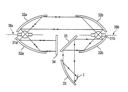
Figure 3a depicts an embodiment of the present
invention wherein two fundamental unit systems, as
depicted in figures 2a 2b, are arranged in a cascading
relationship. The first source 31a is arranged at the
focus of a reflector 32a which is substantially in the
8
CA 02377864 2001-12-31
WO 01/02773 PCT/US00/17199
shape of a full paraboloid such that the light
collected by the reflector 32a is collimated into
parallel rays. A retro-reflector 34 comprisedof a
plane mirror is situated in front of the output face of
the paraboloid reflector 32a covering half of the
aperture of the reflector and aligned perpendicular to
the axis 38a of the reflector such that the light is
reflected back on its own path and refocused back
through the first source 31a. The light collimated by
the upper half of the paraboloid reflector will be
nearly doubled, comprisedof light directly from the arc
itself and from retro-reflection. The output of the
first source 31a is thereby directed into a second
paraboloid reflector 32b having a shape substantially
of a paraboloid with a source 31b located at its focus.
The light from reflector 31b is focused into the arc of
source 31b by reflector 32b.
The total output comprisedof light from the first
source 31a and part of the second source 31b will be
collimated into parallel rays by the lower half of the
second reflector 32b. A redirecting reflector 35,
preferably a planar mirror situated at an angle
relative to the axis 38b of reflector 32b, redirects
the output from reflector 32b into a focusing reflector
33 where it is focused into a spot on the target I.
The portion of light emitted by source 31b in the
direction of the upper half of reflector 32b (facing
upwards as represented by figure 3a) will be collimated
by reflector 32b, focused by the upper half of
reflector 32a through the arc of source 31a and then
retro-reflected back into the arc of source 31a by the
combination of the lower half of reflector 32a and
retro-reflector 34. This retro-reflected light is then
collimated by reflector 32a, focused by reflector 32b
through the arc of source 31b, redirected by the
redirecting reflector 35, and collected by targeting
9
CA 02377864 2001-12-31
WO 01/02773 PCT/US00/17199
reflector 33 together with the other light described
previously into a spot at the target I. Assuming no
losses due to imperfections and identical sources, the
brightnes at the target I produced by such a cascaded
system approaches four times the brightness of a single
source without retro-reflection.
Figure 3b depicts an alternative embodiment of the
present invention, with a similar layout as that
depicted by figure 3a, except that two targets I and Ia
are used instead of one. Comparison of the embodiments
depicted by figures 3a and 3b reveals that retro-
reflector 34 has been omitted from the embodiment of
figure 3a and replaced by a second redirecting
reflector 35a and a second targeting reflector 33a
which are oriented in similar manner to redirecting
reflector 35 and targeting reflector 33 so as to couple
light from sources 31a and 31b into target Ia.
Figure 4 depicts an alternative embodiment of the
present invention which is similar in configuration to
the embodiment depicted by figure 3a except that a
spherical concave mirror 44 is used as the
retro-reflector (as was similarly employed in the
system depicted by figure 2a). The performance of the
system of figure 4 is essentially identical to that of
figure 3a; the total flux concentrated at target I is
essentially four times that of a single source with no
retro-reflection. Similar to figure 2a, reflector 42a
is a half paraboloid as opposed to the full paraboloid
reflector 32a employed in the embodiment depicted by
figure 3a.
Although the above description shows the cascading
of two sources into a single output, in practice more
lamps can be cascaded by using the same fundamental
units of sources and paraboloid reflectors. Figure 5
depicts a preferred embodiment wherein three sources,
51a, 51b, and 51c are cascaded by a series of
CA 02377864 2001-12-31
WO 01/02773 PCT/US00/17199
paraboloid collimating reflectors 52a, 52b, and 52c,
retro-reflector 54, redirectional reflector 55, and
focusing reflector 53 into a spot at target I. In this
case, the theoretical total flux at the target I,
without consideration of the mirror losses at the
reflectors and lamp envelope reflections at the
sources, is 6 times that achievable with a single
source using no retro-reflection.
More lamps can be cascaded similarly with
corresponding paraboloid collimating reflectors to a
desired number (n) of sources.
As will be appreciated by one of ordinary skill in
the art, in the actual implementation of the present
invention, there will be a limit as to how many lamps
can be cascaded according to the present invention
while still producing a marked improvement in flux at
the target. Light flux can be lost to various sources
of imperfections in the system, including the degree of
reflectivity of the reflectors, the Fresnel reflection
at the glass/air interfaces of the lamp envelope for
arc lamps, and any optical aberrations introduced by
the reflectors, the glass envelope of arc lamps, and
the multiple passes.
Besides increasing flux at the target spot,
parabolic cascading condensing and collecting systems
according to the present invention can be used to
produce other desirable results. For example, multiple
sources cascaded according to the present invention can
advantageously be used to provide redundancy in the
radiations sources. In a cascaded system similar to
figures 3a and 3b having two sources, the output
radiation focused on the target spot can be either the
combination of the radiation from both sources, or the
radiation from each source separately. If only one
source is used during normal operation of the system,
and that source fails for some reason, the second
11
CA 02377864 2001-12-31
WO 01/02773 PCT/US00/17199
source can be used instead of changing failed source.
With a cascading system according to the present
invention, the failed source simply can be shut down,
and the second source can be switched on within seconds
without requiring any physical changes to the system.
This feature is especially advantageous when
significant..downtime for the coupling system is
undesirable.
Similarly, the source employed in embodiments of
the present invention can be two chosen which produce
different types of radiation (different wavelengths,
intensities, etc.). For example, in a two source
system, the first source can be a mercury arc lamp, and
the second source can be a sodium arc lamp. Both of
these arc lamps are known as being very efficient,
energy saving lamps. The mercury lamp emits a visible
light having a wavelength in the blue range, while the
sodium lamp emits a visible light having a wavelength
in the yellow range. While these types of lamps when
used separately produce light which is undesirable for
illumination, such as surgical illumination, when these
two wavelengths of light are used in combination, the
overall color output light is more similar to white
light. As will be readily appreciated by one skilled
in the art, this ability to combine lamps which produce
different spectral output allows systems according to
the present invention to be easily tailored to various
spectral output characteristics.
In addition, the size of the paraboloids can be
half paraboloids as described or they can be larger or
smaller in their circular extents depending on
applications. In accordance with one embodiment, the
paraboloid sections are smaller than half paraboloids,
e.g., greater than quarter paraboloids but less than
half paraboloids.
12
CA 02377864 2001-12-31
WO 01/02773 PCT/US00/17199
The invention having been thus described, it will
be apparent to those skilled in the art that the same
may be varied and modified in many ways without
departing from the spirit and scope of the invention.
Any and all such modifications are intended to be
included within the scope of the following claims.
13