Note: Descriptions are shown in the official language in which they were submitted.
CA 02377935 2001-12-21
WO 01/02895 PCT/US00/17964
1
System, Apparatus, and Method for Correcting Vision
Using an Electro-Active Lens
Field of the Invention
The present invention relates to the field of vision correction, and, more
particularly, to a system, apparatus, and method for correcting vision using
an
electro-active lens.
Brief Description of the Drawings
The invention will be more readily understood through the following detailed
description, with reference to the accompanying drawings, in which:
FIG. 1 is a perspective view of an embodiment of an electro-active
phoropter/refractor system 100;
FIG. 2 is a diagrammatic view of an embodiment of another electro-active
phoropter/refractor system 200;
FIG. 3 is a flow diagram of a conventional dispensing practice sequence
300;
FIG. 4 is a flow diagram of an embodiment of dispensing method 400;
FIG. 5 is a perspective view of an embodiment of electro-active eyewear
500;
FIG. 6 is a flow diagram of an embodiment of prescription method 600;
FIG. 7 is a front view of an embodiment of a hybrid electro-active spectacle
lens 700;
FIG. 8 is a section view of an embodiment of hybrid electro-active spectacle
lens 700 taken along section line A-A of Fig. 7;
FIG. 9 is a section view of an embodiment of an electro-active lens 900,
taken along section line Z-Z of Fig. 5;
CA 02377935 2001-12-21
WO 01/02895 PCT/US00/17964
2
FIG. 10 is a perspective view of an embodiment of an electro-active lens
system 1000;
FIG. 11 is a section view of an embodiment of a diffractive electro-active
lens 1100 taken along section line Z-Z of Fig. 5;
FIG. 12 is a front view of an embodiment of an electro-active lens 1200;
FIG. 13 is a section view of an embodiment of the electro-active lens 1200
of Fig. 12 taken along section line Q-Q;
FIG. 14 is a perspective view of an embodiment of a tracking system 1400;
FIG. 15 is a perspective view of an embodiment of an electro-active lens
system 1500;
FIG. 16 is a perspective view of an embodiment of an electro-active lens
system 1600;
FIG. 17 is a perspective view of an embodiment of an electro-active lens
1700;
FIG. 18 is a perspective view of an embodiment of an electro-active lens
1800;
FIG. 19 is a perspective view of an embodiment of an electro-active layer
1900;
FIG. 20 is a perspective view of an embodiment of an electro-active lens
2000;
FIG. 21 is a perspective view of an embodiment of electro-active eyewear
2100;
FIG. 22 is a front view of an embodiment of an electro-active lens 2200;
FIG. 23 is a front view of an embodiment of an electro-active lens 2300;
FIG. 24 is a front view of an embodiment of an electro-active lens 2400;
FIG. 25 is a section view of an embodiment of an electro-active lens 2500
taken along section line Z-Z of Fig. 5;
FIG. 26 is a section view of an embodiment of an electro-active lens 2600
taken along section line Z-Z of Fig. 5;
CA 02377935 2001-12-21
WO 01/02895 PCT/US00/17964
3
FIG. 27 is a flow diagram of an embodiment of dispensing method 2700;
and
FIG. 28 is a perspective view of an embodiment of an electro-active lens
2800.
Detailed Description
In 1998, there were approximately 92 million eye examinations performed in
the United States alone. The vast majority of these examinations involved a
thorough check for eye pathology both internal and external, analysis of
muscle
balance and binocularity, measurement of the cornea and, in many cases, the
pupil,
and finally a refractive examination, which was both objective and subjective.
Refractive examinations are performed to understand / diagnose the
magnitude and type of the refractive error of one's eye. The types of
refractive error
that are currently able to be diagnosed & measured, are myopia, hyperopia,
astigmatism, and presbyopia. Current refractors (phoropters) attempt to
correct
one's vision to 20/20 distance and near and, in some cases, 20/15 distance
vision can
be achieved; however, this is by far the exception.
It should be pointed out that the theoretical limit to which the retina of
one's
eye can process and define vision is approximately 20/10. This is far better
than the
level of vision which is currently obtained by way of both today's refractors
(phoropters) and conventional spectacle lenses. What is missing from these
conventional devices is the ability to detect, quantify and correct for non-
conventional refractive error, such as aberrations, irregular astigmatism, or
ocular
layer irregularities. These aberrations, irregular astigmatism, and/or ocular
layer
irregularities may be as a result of one's visual system or as a result of
aberrations
caused by conventional eyeglasses, or a combination of both.
Therefore, it would be extremely beneficial to have a means for detecting,
quantifying, and correcting one's vision as close to 20/10 or better as
possible.
CA 02377935 2007-09-10
4
Furthermore, it would be beneficial to do this in a very efficient and user
friendly manner.
The present invention utilizes a novel approach in detecting, quantifying and
correcting one's vision. The approach involves several innovative embodiments
utilizing an
electro-active lens. Furthermore, the invention utilizes a novel approach
towards the
selection, dispensing, activating, and programming of electro-active eyewear.
The invention provides an optical lens system comprising: a lens having a
first focal
length; and, an electro-active region coupled to the lens, the electro-active
region, when
activated, altering the focal length of a first portion of the lens system to
a second focal
length, the second focal length different form the first focal length.
The invention also provides an optical lens system comprising: a lens having a
fixed
focal length; and an electro-active region coupled to the lens, the coupled
lens and electro-
active region creating more than one simultaneous focal length for the lens
system when the
electroactive region is activated.
For example, in one inventive embodiment, a novel electro-active
phoropter/refractor
is utilized. This electro-active phoropter/refractor utilizes far fewer lens
components than
today's phoropters and is a fraction of the overall size and/or weight of
today's phoropters. In
fact, this exemplary inventive embodiment consists of only a pair of electro-
active lenses
housed in a frame mounting that provides, either through its own structural
design and/or by
way of a network of conductive wires, electrical power needed to enable the
electro-active
lenses to function properly.
In another aspect, the present invention resides in an ophthalmic lens for a
user,
comprising: a progressive addition region, wherein said progressive addition
region has an
add power therein; and an electro-active optic in optical communication
therewith having an
optical power when activated.
In another aspect, the present invention resides in an optical measuring
system for
quantifying a refractive error of a human eye comprising: a means for altering
a path of
light; and a wave-front analyzer capable of quantifying a refractive error of
a human eye,
wherein quantifying the refractive error comprises receiving non-passive input
from the
human, and wherein the means for altering the path of light comprises an
adaptive optic
modified as the human provides information.
In another aspect, the present invention resides in a method for determining
refractive error of an eye of a person, comprising: using a wave-front
analyzer to measure a
CA 02377935 2007-09-10
4a
first refractive error of the person's eye, the first refractive error
comprising at least one
refractive error other than myopia, hyperopia, or prespbyopia; generating a
first optical
power based at least in part on the first refractive error; receiving a first
non-passive
conscious input from the person sensing the first optical power; and adjusting
the first
optical power based at least in part upon the first non-passive conscious
input, to generate a
second optical power.
In another aspect, the present invention resides in an ophthalmic spectacle
lens
comprising: a vision correcting area having a refractive error correction that
focuses an
image of ambient light on to the retina of an eye for correcting refractive
error of the eye,
wherein the vision correcting area's refractive error correction is determined
at least in part
by a wave front analysis of the eye being corrected; the refractive error
correction corrects
at least in part for non-conventional refractive error, wherein the non-
conventional
refractive error is a refractive error other than myopia, hyperopia,
presbyopia and regular
astigmatism; wherein the refractive error correction is provided at least in
part by a plurality
of optical property variations of said lens, wherein said optical property
variations are
variations in the index of refraction of said lens; and wherein said lens is
capable of being
edged into the shape of an eyeglass frame.
In a further aspect, the present invention resides in an ophthalmic spectacle
lens
comprising: a vision correcting area having a refractive error correction that
focuses an
image of non-polarized light on to the retina of an eye for correcting
refractive error of the
eye, wherein the vision correcting area's refractive error correction is
determined at least in
part by a wave front analysis of the eye being corrected; the refractive error
correction
corrects at least in part for non-conventional refractive error, wherein the
non-conventional
refractive error is a refractive error other than myopia, hyperopia,
presbyopia and regular
astigmatism; wherein the refractive error correction is provided at least in
part by a plurality
of optical property variations of said lens, wherein said optical property
variations are
variations in the index of refraction of said lens; and wherein said lens is
capable of being
edged into the shape of an eyeglass frame.
To assist with understanding certain embodiments of the invention,
explanations of
various terms are now provided. In some situations, these explanations are not
necessarily
intended to be limiting, but, should be read in light of the examples,
descriptions, and claims
provided herein.
CA 02377935 2007-09-10
4b
An "electro-active zone" can include or be included in an electro-active
structure,
layer, and/or region. An "electro-active region" can be a portion and/or the
entirety of an
electro-active layer. An electro-active region can be adjacent to another
electro-active
region. An electro-active region can be attached to another electro-active
region, either
directly, or indirectly with, for example, an insulator between each electro-
active region.
An electro-active layer can be attached to another electro-active layer,
either directly, or
indirectly with, for example, an insulator between each electro-active layer.
"Attaching"
can include bonding, depositing, adhering, and other well-known attachment
methods. A
"controller" can include or be included in a processor, a microprocessor, an
integrated
circuit, an IC,
CA 02377935 2001-12-21
WO 01/02895 PCT/US00/17964
a computer chip, and/or a chip. A "refractor" can include a controller. An
"auto-
refractor" can include a wave front analyzer. "Near distance refractive error"
can
include presbyopia and any other refractive error needed to be corrected for
one to
see clearly at near distance. "Intermediate distance refractive error" can
include the
5 degree of presbyopia needed to be corrected an intermediate distance and any
other
refractive error needed to be corrected for one to see clearly at intermediate
distance.
"Far distance refractive error" can include any refractive error needed to be
corrected
for one to see clearly at far distance. "Near distance" can be from about 6
inches to
about 24 inches, and more preferably from about 14 inches to about 18 inches.
"Intermediate distance" can be from about 24 inches to about 5 feet. "Far
distance"
can be any distance between about 5 feet and infinity, and more preferably,
infinity.
"Conventional refractive error" can include myopia, hyperopia, astigmatism,
and/or
presbyopia. "Non-conventional refractive error" can include irregular
astigmatism,
aberrations of the ocular system, and any other refractive error not included
in
conventional refractive error. "Optical refractive error" can include any
aberrations
associated with a lens optic.
In certain embodiments, a "spectacle" can include one lens. In other
embodiments, a "spectacle" can include more than one lens. A "multi-focal"
lens
can include bifocal, trifocal, quadrafocal, and/or progressive addition lens.
A
"finished" lens blank can include a lens blank that has finished optical
surface on
both sides. A "semi-finished" lens blank can include a lens blank that has, on
one
side only, a finished optical surface, and on the other side, a non-optically
finished
surface, the lens needing further modifications, such as, for example,
grinding and/or
polishing, to make it into a useable lens. "Surfacing" can include grinding
and/or
polishing off excess material to finish a non-finished surface of a semi-
finished lens
blank.
FIG. 1 is a perspective view of an embodiment of electro-active
phoropter/refractor system 100. Frames 110 contain electro-active lens 120,
which
CA 02377935 2001-12-21
WO 01/02895 PCT/US00/17964
6
are connected via a network of conductive wires 130 to an electro-active lens
controller 140 and to an electrical power source 150.
In certain embodiments, the temples (not shown in Fig. 1) of frames 110
contain batteries or power sources such as, for example, a micro-fuel cell. In
other
inventive embodiments, the temple or temples of frame 110 possess the needed
electrical components so that a power cord is plugged directly into an
electrical
outlet and/or the electro-active refractor's controller/programmer 160.
Still in other inventive embodiments, the electro-active lenses 120 are
mounted in a housing assembly which is suspended so one could simply position
one's face properly in order to look through the electro-active lenses while
being
refracted.
While the first inventive embodiment utilizes only a pair of electro-active
lenses, in certain other inventive embodiments, multiple electro-active lenses
are
used. Still in other inventive embodiments, a combination of conventional
lenses
and electro-active lenses are utilized.
FIG. 2 is a diagrammatic view of an exemplary embodiment of an electro-
active refractor system 200 that includes housing assembly 210 that contains
at least
one electro-active lens 220 and several conventional lenses, specifically,
diffractive
lens 230, prismatic lens 240, astigmatic lens 250, and spherical lens 260. A
network
of conductive wires 270 connects the electro-active lens 220 to a power source
275
and to a controller 280, that provides a prescription display 290.
In each inventive embodiment where multiple electro-active lenses and/or a
combination of conventional and electro-active lenses are utilized, the lenses
can be
used to test one's vision in a random and/or non-random one-at-a-time
sequence. In
other inventive embodiments, two or more lenses are added together giving a
total
corrective power in front of each eye as needed.
The electro-active lenses, which are utilized in both the electro-active
phoropter and the electro-active eyewear, are comprised of either a hybrid
and/or
non-hybrid construction. In a hybrid construction, a conventional lens optic
is
CA 02377935 2001-12-21
WO 01/02895 PCT/US00/17964
7
combined with an electro-active zone. In a non-hybrid construction, no
conventional lens optic is used.
As discussed above, the invention differs from today's conventional
dispensing practice sequence 300, which is shown as a flow diagram in FIG. 3.
As
shown at steps 310 and 320, traditionally an eye examination involving a
conventional refractor is followed by obtaining one's prescription and taking
that
prescription to a dispenser. Then, as shown at steps 330 and 340, at the
dispenser
one's frames and lens are selected. As shown at step 350 and 360, the lenses
are
fabricated, edged, and assembled into the frames. Finally, at step 370, the
new
prescription eyeglasses are dispensed and received.
As shown in the flow diagram of FIG. 4, in an exemplary embodiment of
one inventive dispensing method 400, at step 410 the electro-active eyewear is
selected by or for the wearer. At step 420, the frames are fitted to the
wearer. With
the wearer wearing the electro-active eyewear, at step 430, the electronics
are
controlled by the electro-active phoropter/refractor control system which in
most
cases is operated by an eyecare professional and/or technician. However, in
certain
inventive embodiments, the patient or wearer can actually operate the control
system
and thus, control the prescription of their own electro-active lenses. In
other
inventive embodiments, both the patient/wearer and the eyecare professional
and/or
technician work with the controller together.
At step 440, the control system, whether operated by the eyecare
professional, technician, and/or the patient/wearer, is utilized to select
both
objectively or subjectively the best correcting prescription for the
patient/wearer.
Upon selecting the proper prescription to correct the patient/wearer's vision
to it's
optimal correction, the eyecare professional or technician then programs the
patient's/wearer's electro-active eyewear.
In one inventive embodiment, the selected prescription is programmed into
an electro-active eyewear controller, and/or one or more controller
components,
prior to the selected electro-active eyewear being disconnected from the
electro-
CA 02377935 2001-12-21
WO 01/02895 PCT/US00/17964
8
active phoropter/refractor's controller. In other inventive embodiments the
prescription is programmed into the selected electro-active eyewear at a later
time.
In either case the electro-active eyewear is selected, fitted, programmed, and
dispensed at step 450 in a totally different sequence than conventional
eyeglasses are
today. This sequence allows for improved manufacturing, refracting and
dispensing
efficiencies.
Via this inventive method, the patient/wearer literally can select their
eyewear, wear them while the testing of their vision is taking place, and then
have
them programmed for the correct prescription. In most cases, but not all, this
is
done before the patient/wearer leaves the examination chair, thus, ensuring
the total
fabrication and programming accuracy of the patient's final prescription, as
well as
the accuracy of the eye refraction itself. Finally, in this inventive
embodiment the
patient can literally wear their electro-active eyeglasses when they get up
out of the
examination chair and proceed out of the eyecare professional's office.
It should be pointed out that other inventive embodiments allow for the
electro-active phoropter/refractor to simply display or print out the patient
or
wearer's best corrected prescription which is then filled in much the same
manner as
in the past. Currently the process involves taking a written prescription to a
dispensing location where electro-active eyewear (frames and lenses) are sold
and
dispensed.
Still in other inventive embodiments the prescription is sent electronically,
for example, via the Internet, to a dispensing location where electro-active
eyewear
(frames and lenses) are sold.
In the case where the prescription is not filled at the point where the eye
refraction is performed, in certain inventive embodiments an electro-active
eyewear
controller, and/or one or more controller components, is either programmed and
installed into the electro-active eyewear, or directly programmed while
installed in
the electro-active eyewear, following the refraction. In the case where
nothing is
added to the electro-active eyewear, the electro-active eyewear controller,
and/or one
CA 02377935 2001-12-21
WO 01/02895 PCT/US00/17964
9
or- more controller components, is an intricate built-in part of the electro-
active
eyewear and does not need to be added at a later time.
FIG. 27 is a flow diagram of an embodiment of another inventive dispensing
method 2700. At step 2710, the vision of the patient is refracted using any
method.
At step 2720, the prescription for the patient is obtained. At step 2730, the
electro-
active eyewear is selected. At step 2740, the electro-active eyewear is
programmed
with the wearer's prescription. At step 2750, the electro-active eyewear is
dispensed.
FIG. 5 is a perspective view of another inventive embodiment of the electro-
active eyewear 500. In this illustrative example, frames 510 contain generic
electro-
active lenses 520 and 522 that are electrically coupled by connecting wires
530 to
electro-active eyewear controller 540 and power source 550. Section line Z-Z
divides generic electro-active lens 520.
Controller 540 acts as the "brains" of the electro-active eyewear 500, and can
contain at least one processor component, at least one memory component for
storing instructions and/or data for a specific prescription, and at least one
input/output component, such as a port. Controller 540 can perform
computational
tasks such as reading from and writing into memory, calculating voltages to be
applied to individual grid elements based on desired refractive indices,
and/or acting
as a local interface between the patient/user's eyewear and the associated
refractor/phoropter equipment.
In one inventive embodiment, controller 540 is pre-programmed by the
eyecare specialist or technician to meet the patient's convergence aiid
accommodative needs. In this embodiment, this pre-programming is done on
controller 540 while controller 540 is outside the patient's eyewear, and
controller
540 is then inserted into the eyewear after the examination. In one inventive
embodiment, controller 540 is a "read-only" type, supplying the voltage to
grid
elements to obtain the necessary array of refractive indices to correct the
vision for a
specific distance. As the patient's prescription changes, a new controller 540
must
CA 02377935 2001-12-21
WO 01/02895 PCT/USOO/17964
be programmed and inserted into the eyewear by the specialist. This controller
would be of a class of ASIC's, or application specific integrated circuits,
and its
memory and processing commands permanently imprinted.
In another inventive embodiment, the electro-active eyewear controller may
5 be originally programmed by the eyecare specialist or technician when first
dispensed, and later the same controller, or a component thereof, can be
reprogrammed to provide a different correction, as the patient's needs change.
This
electro-active eyewear controller may be extracted from the eyewear, placed in
the
refractor's controller/programmer (shown in Figs. 1 and 2) and reprogrammed
10 during the examination, or reprogrammed, in situ, by the refractor without
removal
from the electro-active eyewear. The electro-active eyewear controller in this
case
could, for example, be of a class of FPGA's, or field programmable gate array
architecture. In this inventive embodiment the electro-active eyewear
controller may
be permanently built into the eyewear and require only an interface link to
the
refractor which issues the reprogramming commands to the FPGA. Part of this
link
would include external AC power to the electro-active eyewear controller
provided
by an AC adapter embedded in the refractor/phoropter or in its controller/
programmer unit.
In another inventive embodiment, the electro-active eyewear acts as the
refractor, and the external equipment operated by the eyecare specialist or
technician
consists of merely a digital and/or analog interface to the electro-active
eyewear's
controller. Thus, the electro-active eyewear controller can also serve as the
controller for the refractor/phoropter. In this embodiment, the necessary
processing
electronics are available to alter the array of grid voltages to the electro-
active
eyewear and reprogram the electro-active eyewear controller with this data
after the
optimal correction for the user is empirically determined. In this case, the
patient
reviews the eye charts through his/her own electro-active eyewear during the
examination and may be unaware that as he/she is selecting the best corrective
CA 02377935 2001-12-21
WO 01/02895 PCT/US00/17964
11
prescription, the controller in their electro-active eyewear is simultaneously
being
reprogrammed electronically.
Another innovative embodiment utilizes an electronic auto-refractor that can
be used as a first step and/or in combination with the electro-active
refractors
(shown in Figs. 1 and 2) such as by way of example, but not limited to
Humphrey's
Auto-refractor & Nikon's Auto-refractor which have been developed or modified
to
provide feed back which is compatible and programmed for use with the
invention's
electro-active lenses. This innovative embodiment is used to measure one's
refractive error, while the patient or wearer is wearing his or her electro-
active
spectacles. This feedback is fed automatically or manually into a controller
and/or
programmer, which then calibrates, programs or reprograms the controller of
the
user/wearer's electro-active spectacles. In this innovative embodiment, one's
electro-active spectacles can be re-calibrated as needed without requiring
full eye
examination or eye refraction.
In certain other inventive embodiments, one's vision correction is corrected,
by way of one's electro-active lenses, to 20/20. This is obtained in most
cases by
correcting one's conventional refractive error (myopia, hyperopia,
astigmatism, and /
or presbyopia). In certain other inventive embodiments, non-conventional
refractive
error such as aberrations, irregular astigmatism, and/or ocular layer
irregularities of
the eye are measured and corrected, as well as conventional refractive error
(myopia,
hyperopia, astigmatism and / or presbyopia). In the inventive embodiments
whereby
aberrations, irregular astigmatism, and/or ocular layer irregularities of the
eye are
corrected in addition to conventional refractive error, one's vision can be
corrected
in many cases to better than 20/20, such as to 20/15, to better than 20/15, to
20/10,
and/or to better than 20/10.
This advantageous error correction is accomplished by utilizing the electro-
active lenses in the eyewear effectively as an adaptive optic. Adaptive optics
have
been demonstrated and in use for many years to correct for atmospheric
distortion in
ground-based astronomical telescopes, as well as for laser transmission
through the
CA 02377935 2007-09-10
12
atmosphere for communications and military applications. In these cases,
segmented or
"rubber" mirrors are usually employed to make small corrections to the wave
front of the
image or laser lightwave. These mirrors are manipulated by mechanical
actuators in most
cases.
Adaptive optics, as applied to vision, is based on active probing of the
ocular system
with a light beam, such as an eye-safe laser, and measures the wavefront
distortion of either
the retinal reflection or the image created on the retina. This form of
wavefront analysis
assumes a plane or spherical probe wave and measures the distortion imparted
on this
wavefront by the ocular system. By comparing the initial wavefront with the
distorted one,
a skilled examiner can determine what abnormalities exist in the ocular system
and
prescribe an appropriate corrective prescription. There are several competing
designs for
wavefront analyzers, however, the adaption of the electro-active lenses
described here for
use as either a transmissive or reflective spatial light modulator to perform
such wavefront
analysis is included within the invention. Examples of wavefront analyzers are
provided in
U.S. Patent Nos. 5,777,719 (Williams) and 5,949,521 (Williams).
In certain embodiments of the present invention, however, small corrections or
adjustments are made to the electro-active lenses so that an image lightwave
is imparted by
a grid array of electrically driven pixels whose index of refraction can be
altered,
accelerating or slowing down the light passing through them by the alterable
index. In this
way, the electro-active lens becomes an adaptive optic, which can compensate
for the
inherent spatial imperfection in the optics of the eye itself in order to
obtain a nearly
aberration-free image on the retina.
In certain inventive embodiments, because the electro-active lens is fully two-
dimensional, fixed spatial aberrations caused by the eye's optical system can
be
compensated for by incorporating the small index of refraction corrections on
top of the
gross vision correction prescription needs of the patient/user. In this way,
vision can be
corrected to a level of better than what could be achieved with common
CA 02377935 2001-12-21
WO 01/02895 PCT/US00/17964
13
convergence and accommodation corrections, and, in many cases, could result in
vision better than 20/20.
In order to achieve this better than 20/20 correction, the patient's ocular
aberrations can be measured by, for example, a modified auto refractor
utilizing a
wavefront sensor or analyzer designed specifically for eye aberration
measurements.
Once the ocular aberrations and other types of non-conventional refractive
error
have been determined in both magnitude and spatially, the controller in the
eyewear
can be programmed to incorporate the 2-D spatially-dependent index of
refraction
changes to compensate for these aberrations and other types of non-
conventional
refractive error in addition to the overall myopia, hyperopia, presbyopia,
and/or
astigmatism correction. Thus, embodiments of the electro-active lens of the
present
invention can electro-actively correct for aberrations of the patient's ocular
system
or created by the lens optic.
Thus, for example, a certain power correction of -3.50 diopters may be
required in a certain electro-active divergent lens to correct a wearer's
myopia. In
this case, an array of different voltages, V,...VN, is applied to the M
elements in the
grid array to generate an array of different indices of refraction, N,...NM,
which give
the electro-active lens a power of -3.50 diopters. However, certain elements
in the
grid array may require up to plus or minus 0.50 units change in their index
N,...NM
to correct for ocular aberrations and/or non-conventional refractive error.
The small
voltage deviations corresponding to these changes is applied to the
appropriate grid
element, in addition to the base myopia-correcting voltages.
In order to detect, quantify, and/or correct as much as possible for non-
conventional refractive error such as irregular astigmatism, ocular refractive
irregularities, such as for example, the tear layer on the front of the
cornea, the front,
or back of the cornea, aqueous irregularities, the front or back of the
lenticular lens,
vitreous irregularities, or for other aberrations caused by the ocular
refractive system
CA 02377935 2001-12-21
WO 01/02895 PCT/US00/17964
14
itself, the electro-active refractor/phoropter is used according to an
embodiment of
the inventive prescription method 600 of FIG. 6.
At step 610, either a conventional refractor, an electro-active refractor
having
both conventional and electro-active lenses, or an electro-active refractor
having
only electro-active lenses, or an auto-refractor, is utilized to measure one's
refractive
error using conventional lens powers such as minus power (for myopes), plus
power
(for hyperopes), cylindrical power and axis (for astigmatism) and prism power
when
needed. Utilizing this approach, one will get what is known today as the
patient's
BVA (best visual acuity) by way of conventional corrective refractive error.
However, certain embodiments of the invention allow for improving one's vision
beyond what today's conventional refractor/phoropters will achieve.
Therefore, step 610 provides for further refinement of one's prescription in a
non-conventional inventive way. In step 610, the prescription, which
accomplishes
this end point, is programmed into the electro-active refractor. The patient
is
properly positioned to look through the electro-active lenses having a multi-
grid
electro-active structure into a modified and compatible autorefractor or a
wavefront
analyzer, which automatically measures precisely the refractive error. This
refractive error measurement detects and quantifies as much non-conventional
refractive errors as possible. This measurement is taken through a small,
approximately 4.29 mm, targeted area of each electro-active lens, while
automatically computing the necessary prescription to achieve the best focus
on the
fovea along the line-of-sight while the patient is looking through the
targeted area of
the electro-active lens. Once this measurement is made this non-conventional
correction is either stored in the controller/programmer memory for future use
or it
is then programmed into the controller that controls the electro-active
lenses. This,
of course, is repeated for both eyes.
At step 620, the patient or wearer now may at their option elect to use a
control unit which will allow them to further refine the conventional
refractive error
correction, the non-conventional refractive error correction, or a combination
of
CA 02377935 2001-12-21
WO 01/02895 PCT/US00/17964
both, and thus the final prescription, to their liking. Alternatively, or in
addition, the
eyecare professional may refine it, until in some cases no further refinement
is
performed. At this point, an improved BVA for the patient, better than any
available
via conventional techniques, will be achieved.
5 At step 630, any further refined prescription is then programmed into the
controller, which controls the electro-active lenses' prescription. At step
640, the
programmed electro-active spectacles are dispensed.
While the preceding steps 610 through 640 present an embodiment of one
inventive method, depending upon the eyecare professional's judgement or
10 approach, numerous different but similar approaches could be used to
detect,
quantify, and/or correct one's vision using solely electro-active
refractors/phoropters
or in combination with wavefront analyzers. Any method, no matter in what
sequence, that utilizes an electro-active refractor/phoropter to detect,
quantify,
and/or correct one's vision, whether in conjunction with a wavefront analyzer
or not,
15 is considered part of the invention. For example, in certain inventive
embodiments,
steps 610 through 640 may be performed in either a modified way or even a
different sequence. Furthermore, in embodiments of certain other inventive
methods, the targeted area of the lens referred to in step 610 is within the
range of
about 3.0 millimeters in diameter to about 8.0 millimeters in diameter. Still
in other
inventive embodiments, the targeted area can be anywhere from about 2.0
millimeters in diameter up to the area of the entire lens.
Although this discussion has thus far concentrated on refraction using
various forms of electro-active lenses alone or in combination with wavefront
analyzers to perform the eye examination of the future, there is another
possibility
that new emerging technology may allow simply for objective measurements, thus
potentially eliminating the need for a patient's communicated response or
interaction. Many of the inventive embodiments described and/or claimed herein
are
intended to work with any type of measuring system, whether objective,
subjective,
or a combination of both.
CA 02377935 2001-12-21
WO 01/02895 PCT/USOO/17964
16
Turning now to the electro-active lens itself, as discussed above, an
embodiment of the present invention concerns an electro-active
refractor/phoropter
that has a novel electro-active lens, that can either be of a hybrid or of a
non-hybrid
construction. By hybrid construction it is meant a combination of a
conventional
single vision or a multifocal lens optic, with at least one electro-active
zone located
on the front surface, back surface, and/or in between the front and back
surfaces, the
zone consisting of an electro-active material having the necessary electro-
active
means to change focus electrically. In certain embodiments of the invention,
the
electro-active zone is specifically placed either inside the lens or on the
back
concave surface of the lens to protect it from scratches and other normal
wear. In
the embodiment where the electro-active zone is included as part of the front
convex
surface, in most cases a scratch resistant coating is applied. The combination
of the
conventional single vision lens or a conventional multifocal lens and the
electro-
active zone gives the total lens power of the hybrid lens design. By non-
hybrid it is
meant a lens which is electro-active whereby mostly 100% of its refractive
power is
generated solely by its electro-active nature.
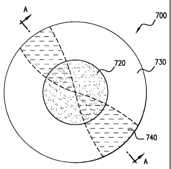
FIG. 7 is a front view, and FIG. 8 is a section view taken along line A-A, of
an embodiment of an exemplary hybrid electro-active spectacle lens 700. In
this
illustrative example, lens 700 includes a lens optic 710. Attached to lens
optic 710
is an electro-active layer 720, that can have one or more electro-active
regions that
occupy all or a portion of electro-active layer 720. Also attached to lens
optic 710
and at least partially surrounding electro-active layer 720 is framing layer
730. Lens
optic 710 includes an astigmatic power correction region 740 having an
astigmatic
axis A-A rotated, in this specific example only, approximately 45 degrees
clockwise
from horizontal. Covering electro-active layer 720 and framing layer 730 is an
optional cover layer 750.
As will be discussed further, electro-active layer 720 can include a liquid
crystal and/or a polymer gel. Electro-active layer 720 can also include an
alignment
layer, a metallic layer, a conducting layer, and/or an insulating layer.
CA 02377935 2001-12-21
WO 01/02895 PCT/US00/17964
17
In an alternative embodiment, astigmatic correction region 740 is eliminated
so that lens optic 710 corrects for sphere power only. In another alternative
embodiment, lens optic 710 can correct for either far distance, near distance,
and/or
both, and any sort of conventional refractive error, including spheric,
cylindric,
prismatic, and/or aspheric errors. Electro-active layer 720 can also correct
for near
distance, and/or for non-conventional refractive error such as aberrations. In
other
embodiments, electro-active layer 720 can correct any sort of conventional or
non-
conventional refractive error and lens optic 710 can correct for conventional
refractive error.
It has been discovered that an electro-active lens having a hybrid
construction approach has certain distinct advantages over that of a non-
hybrid lens.
These advantages are lower electrical power needs, smaller battery size,
longer
battery life expectancy, less complex electrical circuitry, fewer conductors,
fewer
insulators, lower manufacturing costs, increased optical transparency, and
increased
structural integrity. However, it must be noted that non-hybrid electro-active
lenses
have their own set of advantages, including reduced thickness and mass
manufacturing.
It also has been discovered that both the non-hybrid, and in some
embodiments, the full field hybrid and partial field hybrid approach, will
allow for
mass manufacturing of a very limited number of SKUs (Stock Keeping Units)
when,
for example, the electro-active structural design utilized is that of a multi-
grid
electro-active structure. In this case, it would only be necessary when mass
manufacturing to focus primarily on a limited number of differentiated
features such
as curvature and size for the wearer's anatomical compatibility.
To understand the significance of this improvement, one must understand the
number of traditional lens blanks needed to address most prescriptions. About
95%
of corrective prescriptions include a sphere power correction within a range
of -6.00
diopters to +6.00 diopters, in 0.25 diopter increments. Based on this range,
there are
about 49 commonly prescribed sphere powers. Of those prescriptions that
include
CA 02377935 2001-12-21
WO 01/02895 PCT/US00/17964
18
an astigmatism correction, about 95% fall within the range of -4.00 diopters
to +
4.00 diopters, in 0.25 diopter increments. Based on this range, there are
about 33
commonly prescribed astigmatic (or cylinder) powers. Because astigmatism has
an
axis component, however, there are about 360 degrees of astigmatic axis
orientations, which are typically prescribed in 1 degree increments. Thus,
there are
360 different astigmatic axis prescriptions.
Moreover, many prescriptions include a bifocal component to correct for
presbyopia. Of those prescriptions that have a presbyopic correction, about
95% fall
within the range of +1.00 to +3.00 diopters, in 0.25 diopter increments,
thereby
resulting in about 9 commonly prescribed presbyopic powers.
Because some embodiments of the invention can provide for spherical,
cylindrical, axis, and presbyopic corrections, one non-hybrid electro-active
lens can
serve the 5,239,080 (= 49 x 33 x 360 x 9) different prescriptions. Thus, one
non-
hybrid electro-active lens can eliminate the need to mass manufacture and/or
stock
numerous lens blank SKUs, and of possibly greater importance, can eliminate
the
need to grind and polish each lens blank to a particular patient's
prescription.
To account for the various lens curvatures that may be needed to
accommodate anatomical issues such as face shape, eyelash length, etc.,
somewhat
more than one non-hybrid electro-active lens SKU could be mass manufactured
and/or stocked. Nevertheless, the number of SKU's could be reduced from
millions
to about five or less.
In the case of the hybrid electro-active lens, it has been discovered that by
correcting for conventional refractive error with the lens optic and utilizing
a mostly
centered electro-active layer, it is possible to also reduce the number of
SKU's
needed. Referring to FIG. 7, lens 700 can be rotated as needed to place
astigmatic
axis A-A in the needed position. Thus, the number of hybrid lens blanks needed
can
be reduced by a factor of 360. Moreover, the electro-active zone of the hybrid
lens
can provide the presbyopic correction, thereby reducing by a factor of 9 the
number
of lens blanks needed. Thus, a hybrid electro-active lens embodiment can
reduce
CA 02377935 2001-12-21
WO 01/02895 PCT/US00/17964
19
from more than 5 million to 1619 (= 49 x 33) the number of lens blanks needed.
Because it may be reasonably possible to mass manufacture and/or stock this
number of hybrid lens blank SKUs, the need for grinding and polishing may be
eliminated.
Nevertheless, grinding and polishing semi-finished hybrid lens blanks into
finished lens blanks remains a possibility. FIG. 28 is a perspective view of
an
embodiment of a semi-finished lens blank 2800. In this embodiment, semi-
finished
lens blank 2800 has a lens optic 2810 with a finished surface 2820, an
unfinished
surface 2830, and a partial field electro-active layer 2840. In another
embodiment,
semi-finished lens blank 2800 can have a full field electro-active layer.
Moreover,
the electro-active structure of semi-finished lens blank 2800 can be multi-
grid or
single interconnect. Further, semi-finished lens blank 2800 can have
refractive
and/or diffractive characteristics.
In either the hybrid or the non-hybrid embodiment of the electro-active lens,
a significant number of needed correcting prescriptions can be created and
customized by the electro-active lens which can be adjusted and controlled by
a
controller that has been customized and/or programmed for the patient's
specific
prescription needs. Thus, the millions of prescriptions and numerous lens
styles,
single vision lens blanks, as well as the numerous multifocal semi-finished
lens
blanks may be no longer needed. In fact, most lens and frame manufacturing and
distribution, as we know it may be revolutionized.
It should be noted that the invention includes both non-hybrid electro-active
lenses, as well as full and partial field specific hybrid electro-active
lenses that are
either pre-manufactured electronic eyewear (frame and/or lenses) or customized
electronic eyewear at the time of delivery to the patient or customer. In the
case of
the eyewear being pre-fabricated and assembled, both the frames and the lenses
are
pre-made with the lenses already edged and put into the eyeglass frames. Also
considered to be part of the invention is the programmable and re-programmable
controller as well as the mass production of frames and lenses having the
necessary
CA 02377935 2001-12-21
WO 01/02895 PCT/US00/17964
electric components which can be prefabricated and sent to the eyecare
professional's site or some other site for either the installation of, for
example, a
programmed controller, and/or one or more controller components, for the
patient's
prescription.
5 In certain cases the controller, and/or one or more controller components,
can
be part of the pre-manufactured frame and electro-active lens assembly and
then
programmed at either the eyecare professional's site or some other site. The
controller, and/or one or more controller components, can be in the form, for
example, of a chip or a thin film and can be housed in the frame, on the
frame, in the
10 lens, or on the lens of the eyeglasses. The controller, and/or one or more
controller
components, can be re-programmable or not re-programmable based upon the
business strategy to be implemented. In the case where the controller, and/or
one or
more controller components, is re-programmable, this will allow for the
repeated
updating of one's prescriptions as long as the patient or customer is happy
with his
15 or her eyeglass frames as well as the cosmetic appearance and functionality
of the
electro-active lenses.
In the case of the latter, the non-hybrid and hybrid electro-active lens
embodiments just discussed, the lenses must be structurally sound enough in
order
to protect the eye from injury from a foreign object. In the United States,
most
20 eyewear lenses must pass a FDA required impact test. In order to meet these
requirements, it is important that a support structure is built into or on the
lens. In
the case of the hybrid type, this is accomplished, for example, utilizing
either a
prescription or non-prescription single vision or multifocal lens optic as a
structural
base. For example, the structural base for the hybrid type can be made out of
polycarbonate. In the case of the non-hybrid lens, in certain embodiments, the
electro-active material selected and thickness accounts for this needed
structure. In
other embodiments, the non-prescription carrier base or substrate onto which
the
electro-active material is positioned accounts for this needed protection.
CA 02377935 2001-12-21
WO 01/02895 PCT/US00/17964
21
When utilizing electro-active zones in spectacle lenses in certain hybrid
designs, it can be essential to maintain proper distance correction when a
power
interruption to the lenses occurs. In the case of a battery or wiring failure,
in some
situations it could be disastrous if the wearer was driving an automobile or
piloting
an airplane and their distance correction was lost. To prevent such
occurrences, the
inventive design of the electro-active spectacle lenses can provide for the
distance
correction to be maintained when the electro-active zones is in the OFF
position (the
inactivated or unpowered state). In an embodiment of this invention, this can
be
accomplished by providing the distance correction with a conventional fixed
focal -
length optic, whether it be a refractive or a diffractive hybrid type. Any
additional
add power, therefore, is provided by the electro-active zone(s). Thus, a fail-
safe
electro-active system occurs, because the conventional lens optic will
preserve the
wearer's distance correction.
FIG. 9 is a side view of an exemplary embodiment of another electro-active
lens 900 having a lens optic 910 that is index matched to an electro-active
layer 920.
In this illustrative example, the diverging lens optic 910, having an index of
refraction, n,, provides distance correction. Attached to lens optic 910 is
the electro-
active layer 920, which can have an unactivated state, and a number of
activated
states. When electro-active layer 920 is in its unactivated state, it has an
index of
refraction nz, which approximately matches the index of refraction, n,, of
lens optic
910. More accurately, when unactivated, nz is within 0.05 refractive units of
n,.
Surrounding electro-active layer 920 is framing layer 930, which has an index
of
refraction, n3, that also approximately matches the index of refraction, n,,
of lens
optic 910 within 0.05 refractive units of n,.
FIG. 10 is a perspective view of an exemplary embodiment of another
electro-active lens system 1000. In this illustrative example, electro-active
lens
1010 includes a lens optic 1040 and an electro-active layer 1050. A
rangefinder
transmitter 1020 is positioned on electro-active layer 1050. Also, a
rangefinder
detector/receiver 1030 is positioned on electro-active layer 1050. In an
alternative
CA 02377935 2001-12-21
WO 01/02895 PCT/US00/17964
22
embodiment, either transmitter 1020 or receiver 1030 can be positioned in
electro-
active layer 1050. In other alternative embodiments, either transmitter 1020
or
receiver 1030 can be positioned in or on lens optic 1040. In other embodiments
either transmitter 1020 or receive 1030 can be positioned on outer covering
layer
1060. Further, in other embodiments, 1020 and 1030 can be positioned on any
combination of the preceding.
FIG. 11 is a side view of an exemplary embodiment of a diffractive electro-
active lens 1100. In this illustrative example, lens optic 1110 provides
distance
correction. Etched on one surface of lens optic 1110 is diffractive pattern
1120,
having an index of refraction, nl. Attached to lens optic 1110 and covering
diffractive pattern 1120 is electro-active layer 1130, which has an index of
refraction, n2, that approximates nl, when electro-active layer 1130 is in its
unactivated state. Also attached to lens optic 1110 is framing layer 1140,
which is
constructed of material mostly identical to lens optic 1110, and which at
least
partially surrounds electro-active layer 1120. A covering 1150 is attached
over
electro-active layer 1130 and framing layer 1140. The framing layer 1140 can
also
be an extension of lens optic I 110, in which can no actual layer is added,
however,
lens optic 1110 is fabricated so as to frame or circumscribe electro-active
layer 1130.
FIG. 12 is a front view, and FIG. 13 a side view, of an exemplary
embodiment of an electro-active lens 1200 having a multi-focal optic 1210
attached
to an electro-active framing layer 1220. In this illustrative example, multi-
focal
optic 1210 is of a progressive addition lens design. Moreover, in this
illustrative
example, multi-focal optic 1210 includes a first optical refraction focus zone
1212
and a second progressive addition optical refraction focus zone 1214. Attached
to
multi-focal optic 1210 is electro-active framing layer 1220 having an electro-
active
region 1222 that is positioned over second optical refraction focus zone 1214.
A
cover layer 1230 is attached to electro-active framing layer 1220. It should
be noted
that the framing layer can be either electro-active or non-electro-active.
When the
framing layer is electro-active, insulating material is utilized to insulate
the activated
CA 02377935 2001-12-21
WO 01/02895 PCT/US00/17964
23
region from the non-activated region.
In most inventive cases, but not all, in order to program the electro-active
eyewear to correct one's vision'to its optimum, thus, correcting for non-
conventional
refractive error it is necessary to track the line-of-sight of each eye by way
of
tracking the eye movements of the patient or wearer.
FIG. 14 is a perspective view of an exemplary embodiment of a tracking
system 1400. Frames 1410 contain electro-active lens 1420. Attached to the
backside of electro-active lens 1420 (that side closest to the wearer's eyes,
also
referred to as the proximal side), are a tracking signal sources 1430, such as
light
emitting diodes. Also attached to the backside of electro-active lens 1420 are
tracking signal receivers 1440, such as light reflection sensors. Receivers
1440, and
possibly sources 1430, are connected to a controller (not shown) that includes
in its
memory instructions to enable tracking. Utilizing this approach it is possible
to
locate very precisely the eye movements up, down, right, left and any
variation
thereof. This is needed as certain types, but not all, of non-conventional
refractive
error needs to be corrected and isolated within one's line-of-sight (for
example, in
the case of a specific corneal irregularity or bump that moves as the eye
moves).
In various alternative embodiments, sources 1430 and/or receivers 1440 can
be attached to the backside of frames 1410, embedded in the backside of frames
1410, and/or embedded in the backside of lenses 1420.
An important portion of any spectacle lens, including the electro-active
spectacle lens, is the portion used to produce the sharpest image quality
within the
user's field of view. While a healthy person can see approximately 90 degrees
to
either side, the sharpest visual acuity is located within a smaller field of
view,
corresponding to the portion of the retina with the best visual acuity. This
region of
the retina is known as the fovea, and is approximately a circular region
measuring
0.40mm in diameter on the retina. Additionally, the eye images the scene
through
the entire pupil diameter, so the pupil diameter will also affect the size of
the most
critical portion of the spectacle lens. The resulting critical region of the
spectacle
CA 02377935 2001-12-21
WO 01/02895 PCT/US00/17964
24
lens is simply the sum of the diameter of the eye's pupil diameter added to
the
projection of the fovea's field of view onto the spectacle lens.
The typical range for the eye's pupil diameter is from 3.0 to 5.5 mm, with a
most common value of 4.0 mm. The average fovea diameter is approximately 0.4
mm.
The typical range for the size of the fovea's projected dimension onto the
spectacle lens is affected by such parameters as the length of the eye, the
distance
from the eye to the spectacle lens, etc.
The tracking system of this specific inventive embodiment then locates the
regions of the electro-active lens that correlate to the eye movements
relative to the
fovial region of the patient's retina. This is important as the invention's
software is
programmed to always correct for the non-conventional refractive error that is
correctable as the eye moves. Thus, it is necessary in most, but not all,
inventive
embodiments that correct for non-conventional refractive error to electro-
actively
alter the area of the lens that the line-of-sight is passing through as the
eyes fixate
their target or gaze. In other words, in this specific inventive embodiment
the vast
majority of the electro-active lens corrects for conventional refractive error
and as
the eye moves the targeted electro-active area focus moves as well by way of
the
tracking system and software to correct for the non-conventional refractive
error
taking into account the angle in which the line-of-sight intersects different
sections
of the lens and factoring this into the final prescription for that specific
area.
In most, but not all, inventive embodiments, the tracking system and
enabling software is utilized to correct one's vision to its maximum, while
looking
or gazing at distant objects. When looking at near points the tracking system,
if
used, is utilized to both calculate the range of near point focus in order to
correct for
one's accommodative and convergence near or intermediate range focusing needs.
This of course is programmed into the electro-active eyewear controller,
and/or one
or more controller components, as part of the patient or wearers'
prescription. In
still other inventive embodiments a range finder and/or tracking system is
CA 02377935 2001-12-21
WO 01/02895 PCT/US00/17964
incorporated either into the lenses and/or frames.
It should be pointed out that in other inventive embodiments such as those
that correct for certain types of non-conventional refractive error, such as,
for
example, irregular astigmatism, in most but not all cases, the electro-active
lenses do
5 not need to track the patient or wearer's eye. In this case the overall
electro-active
lens is programmed to correct for this, as well as the other conventional
refractive
error of the patient.
Also, since aberrations are directly related to the viewing distance, it has
been discovered that they can be corrected in relation to the viewing
distance. That
10 is, once the abenation or aberrations have been measured, it is possible to
correct for
these aberrations in the electro-active layer by way of segregating the
electro-active
regions so as to electro-actively correct for aberrations for specific
distances such as
distance vision, intermediate vision, and/or near vision. For example, the
electro-
active lens can be segregated into a far vision, intermediate vision, and near
vision
15 corrective zones, each the software controlling each zone causing the zone
to correct
for those aberrations that impact the corresponding viewing distance.
Therefore in
this specific inventive embodiment, where the electro-active layer is
segregated for
different distances whereby each segregated region corrects for specific
aberrations
of a specific distance, it is possible to correct for non-refractive error
without a
20 tracking mechanism.
Finally, it should be pointed out that in another inventive embodiment, it is
possible to accomplish the correction of the non-conventional refractive
error, such
as that caused by aberrations, without physically separating the electro-
active
regions and without tracking. In this embodiment, using the viewing distance
as an
25 input, the software adjusts the focus of a given electro-active area to
account for the
correction needed for an aberration that would otherwise impact the vision at
the
given viewing distance.
Furthermore, it has been discovered that either a hybrid or non-hybrid
electro-active lens can be designed to have a full field or a partial field
effect. By
CA 02377935 2001-12-21
WO 01/02895 PCT/US00/17964
26
full field effect it is meant that the electro-active layer or layers cover
the vast
majority of the lens region within an eyeglass frame. In the case of a full
field, the
entire electro-active area can be adjusted to the desired power. Also, a full
field
electro-active lens can be adjusted to provide a partial field. However, a
partial field
electro-active specific lens design can not be adjusted to a full field due to
the
circuitry needed to make it partial field specific. In the case of a full
field lens
adjusted to become a partial field lens, a partial section of the electro-
active lens can
be adjusted to the desired power.
FIG. 15 is a perspective view of an exemplary embodiment of another
electro-active lens system 1500. Frames 1510 contain electro-active lenses
1520,
which have a partial field 1530.
For purposes of comparison, FIG. 16 is a perspective view of an exemplary
embodiment of yet another electro-active lens system 1600. In this
illustrative
example, frames 1610 contain electro-active lenses 1620, which have a full
field
1630.
In certain inventive embodiments the multifocal electro-active optic is pre-
manufactured and in some cases, due to the significantly reduced number of
SKU's
required, even inventoried at the dispensing location as a finished multifocal
electro-
active lens blank. This inventive embodiment allows for the dispensing site to
simply fit and edge the inventoried multifocal electro-active lens blanks into
the
electronic enabling frames. While in most cases this invention could be of a
partial
field specific type electro-active lens, it should be understood this would
work for
full field electro-active lenses, as well.
In one hybrid embodiment of the invention, a conventional single vision lens
optic being of aspheric design or non-aspheric design having a toric surface
for
correction of astigmatism and a spherical surface is utilized to provide the
distance
power needs. If astigmatic correction is needed the appropriate power single
vision
lens optic would be selected and rotated to the proper astigmatic axis
location. Once
this is done the single vision lens optic could be edged for the eye wire
frame style
CA 02377935 2001-12-21
WO 01/02895 PCT/US00/17964
27
and size. The electro-active layer could then be applied on the single vision
lens
optic or the electro-active layer can be applied prior to edging and the total
lens unit
can be edged later. It should be pointed out that, for edging whereby the
electro-
active layer is affixed to a lens optic, either a single vision or multifocal
electro-
active optic, prior to edging, an electro-active material such as a polymer
gel may be
advantageous over a liquid crystal material.
The electro-active layer can be applied to compatible lens optics by way of
different technologies known in the art. Compatible lens optics are optics
whose
curves and surfaces will accept the electro-active layer properly from the
stand point
of bonding, aesthetics, and/or proper final lens power. For example, adhesives
can
be utilized applying the adhesive directly to the lens optic and then laying
down the
electro-active layer. Also, the electro-active layer can be manufactured so it
is
attached to a release film in which case it can be removed and reattached
adhesively
to the lens optic. Also, it can be attached to two-way film carrier of which
the
carrier itself is attached adhesively to the lens optic. Furthermore, it can
be applied
utilizing a SurfaceCasting technique in which case the electro-active layer is
created
in-situ.
In previously mentioned hybrid embodiment, FIG. 12, a combination of a
static and non-static approach is used to satisfy one's mid and near point
vision
needs, a multifocal progressive lens 1210 having the proper needed distance
correction and having, for example, approximately +1.00 diopter of full near
add
power is utilized in lieu of the single vision lens optic. In utilizing this
embodiment
the electro-active layer 1220 can be placed on either side of the multifocal
progressive lens optic, as well as buried inside the lens optic. This electro-
active
layer is utilized to provide for additional add power.
When utilizing a lower add power in the lens optic than required by the
overall multifocal lens, the final add power is the total additive power of
the low
multifocal add and the additional required near power generated by way of the
electro-active layer. For example only; if a multifocal progressive addition
lens
CA 02377935 2001-12-21
WO 01/02895 PCT/US00/17964
28
optic had an add power of +1.00 and the electro-active layer created a near
power of
+1.00 the total near power for the hybrid electro-active lens would be +2.OOD.
Utilizing this approach, it is possible to significantly reduce unwanted
perceived
distortions from multi-focal lenses, specifically progressive addition lenses.
In certain hybrid electro-active embodiments whereby a multifocal
progressive addition lens optic is utilized, the electro-active layer is
utilized to
subtract out unwanted astigmatism. This is accomplished by neutralizing or
substantially reducing the unwanted astigmatism through an electro-actively
created
neutralizing power compensation solely in the areas of the lens where the
unwanted
astigmatism exists.
In certain inventive embodiments decentration of the partial field is needed.
When applying a decentered partial field electro-active layer it is necessary
to align
the electro-active layer in such a way to accommodate the proper astigmatic
axis
location of the single vision lens optic so as to allow for correcting one's
astigmatism, should it exist, as well as locating the electronic variable
power field in
the proper location for one's eyes. Also, it is necessary with the partial
field design
to align the partial field location to allow for proper decentration placement
with
regards to the patient's pupillary needs. It has been further discovered that
unlike
conventional lenses where the static bifocal, multifocal or progressive
regions are
always placed to always be below one's distance-viewing gaze, the use of an
electro-
active lens allows for certain manufacturing freedom not available to
conventional
multifocal lenses. Therefore, some embodiments of the invention, the electro-
active
region is located where one would typically find the distance, intermediate,
and near
vision regions of a conventional non-electro-active multi-focal lens. For
example,
the electro-active region can be placed above the 180 meridian of the lens
optic,
thereby allowing the multifocal near vision zone to be occasionally provided
above
the 180 meridian of the lens optic. Providing the near vision zone above the
180
meridian of the lens optic can be especially useful for those spectacle
wearers
working at close distances to an object directly in front or overhead of the
wearer,
CA 02377935 2001-12-21
WO 01/02895 PCT/US00/17964
29
such as working with a computer monitor, or nailing picture frames overhead.
In the case of a non-hybrid electro-active lens or both the hybrid full field
lens and for example, a 35mm diameter hybrid partial field lens, the electro-
active
layer, as stated before, can be applied directly to either the single vision
lens optic,
or pre-manufactured with a lens optic creating electro-active finished
multifocal lens
blanks, or the multifocal progressive lens optic, prior to edging the lens for
the shape
of the frame's lens mounting. This allows for pre-assembly of electro-active
lens
blanks, as well as being able to inventory stock finished, but not edged
electro-active
lens blanks, thus allowing for just in time eyeglass fabrication at any
channel of
distribution, including the doctor or optician's offices. This will allow all
optical
dispensaries to be able to offer fast service with minimal needs for expensive
fabrication equipment. This benefits manufacturers, retailers, and their
patients, the
consumers.
Considering the size of the partial field, it has been shown, for example, in
one inventive embodiment that the partial field specific region could be a
35mm
diameter centered or decentered round design. It should be pointed out that
the
diameter size can vary depending upon the needs. In certain inventive
embodiments
22mm, 28mm, 30mm, & 36mm round diameters are utilized.
The size of the partial field can depend on the structure of the electro-
active
layer and/or the electro-active field. At least two such structures are
contemplated as
within the scope of the present invention, namely, a single-interconnect
electro-
active structure and a multi-grid electro-active structure.
FIG. 17 is a perspective view of an embodiment of an electro-active lens
1700 having a single interconnect structure. Lens 1700 includes a lens optic
1710
and an electro-active layer 1720. Within electro-active layer 1720, an
insulator 1730
separates an activated partial field 1740 from a framed non-activated field
(or
region) 1750. A single wire interconnect 1760 connects the activated field to
a
power supply and/or controller. Note that in most, if not all, embodiments, a
single-
interconnect structure has a single pair of electrical conductors coupling it
to a
CA 02377935 2001-12-21
WO 01/02895 PCT/US00/17964
power source.
FIG. 18 is a perspective view of an embodiment of an electro-active lens
1800 having a multi-grid structure. Lens 1800 includes a lens optic 1810 and
an
electro-active layer 1820. Within electro-active layer 1820, an insulator 1830
5 separates an activated partial field 1840 from a framed non-activated field
(or
region) 1850. A plurality of wire interconnects 1860 connect the activated
field to a
power supply and/or controller.
When utilizing the smaller diameters for the partial field, it has been
discovered that the electro-active thickness differential from edge to center
of the
10 partial field specific region when utilizing a single interconnect electro-
active
structure can be minimized. This has a very positive role in minimizing the
electrical power needs, as well as number of electro-active layers required,
especially for the single interconnect structure. This is not always the case
for the
partial field specific region whereby it utilizes a multi-grid electro-active
structure.
15 When utilizing a single interconnect electro-active structure, in many
inventive
embodiments, but not all, multiple single interconnect electro-active
structures are
layered within or on the lens so as to allow for multiple electro-active
layers creating
for example, a total combined electro-active power of +2.50D. In this
inventive
example only, five +0.50D single interconnect layers could be placed one on
top of
20 each other separated only in most cases, by insulating layers. In this way,
the proper
electrical power can create the necessary refractive index change for each
layer by
way of minimizing the electrical needs of one thick single interconnect layer
which
in some cases would be impractical to energize properly.
It should be further pointed out in the invention, certain embodiments having
25 multiple single interconnect electro-active layers can be energized in a
preprogrammed sequence to allow one to have the ability to focus over a range
of
distances. For example, two +0.50D single interconnect electro-active layers
could
be energized, creating a+l .00 intermediate focus to allow for a +2.OOD
presbyope to
see at finger tip distance and then two additional +0.50D single interconnect
electro-
CA 02377935 2001-12-21
WO 01/02895 PCT/US00/17964
31
active layers could be energized to give the +2.OOD presbyope the ability to
read as
close as 16 inches. It should be understood that the exact number of electro-
active
layers, as well as the power of each layer, can vary depending upon the
optical
design, as well as the total power needed to cover a specific range of near
and
intermediate vision distances for a specific presbyope.
Furthermore, in certain other inventive embodiments, a combination of either
one or more single interconnect electro-active layers are present in the lens
in
combination with a multi-grid electro-active structural layer. Once again,
this gives
one the ability of focusing for a range of intermediate and near distances
assuming
the proper programming. Finally, in other inventive embodiments, only a multi-
grid
electro-active structure is utilized either in a hybrid or non-hybrid lens.
Either way,
the multi-grid electro-active structure in combination with a properly
programmed
electro-active eyewear controller, and/or one or more controller components,
would
allow for the ability to focus over a broad range of intermediate and near
distances.
Also, semi-finished electro-active lens blanks that would allow for surfacing
are also within the scope of the invention. In this case, either a decentered,
centered,
partial field electro-active layer incorporated with the blank, or a full
field electro-
active layer is incorporated with the blank and then surfaced to the correct
prescription needed. -
In certain embodiments the variable power electro-active field is located over
the entire lens and adjusts as a constant spherical power change over the
entire
surface of the lens to accommodate one's working near vision focusing needs.
In
other embodiments the variable power field adjusts over the entire lens as a
constant
spherical power change while at the same time creating an aspherical
peripheral
power effect in order to reduce distortion and aberrations. In some of the
embodiments mentioned above, the distance power is corrected by way of either
the
single vision, multifocal finished lens blanks, or the multifocal progressive
lens
optic. The electro-active optical layer corrects mainly for the working
distance
focusing needs. It should be noted this is not always the case. It is
possible, in some
CA 02377935 2001-12-21
WO 01/02895 PCT/US00/17964
32
cases, to utilize either a single vision, multifocal finished lens optic, or
multifocal
progressive lens optic for distance spherical power only and correct near
vision
working power and astigmatism through the electro-active layer or utilize
either the
single vision or multifocal lens optic to correct astigmatism only and correct
the
sphere power and near vision working power through the electro-active layer.
Also,
it is possible to utilize a plano, single vision, multifocal finished lens
optic, or
progressive multifocal lens optic and correct the distance sphere and
astigmatism
needs by way of the electro-active layer.
It should be pointed out that with the invention, the power correction needed,
whether prismatic, spherical or aspheric power as well as total distance power
needs,
mid range power needs and near point power needs, can be accomplished by way
of
any number of additive power components. These include the utilization of a
single
vision or finished multifocal lens optic providing all the distance spherical
power
needs, some of the distance spherical power needs, all of the astigmatic power
needs,
some of the astigmatic power needs, all of the prismatic power needs, some of
the
prismatic power needs, or any combination of the above when combined with the
electro-active layer, will provide for one's total focusing needs.
It has been discovered that the electro-active layer allows for the
utilization
of adaptive optic correction-like techniques to maximize one's vision through
his or
her electro-active lenses either prior or after final fabrication. This can be
accomplished by way of allowing the patient or intended wearer to look through
the
electro-active lens or lenses and adjusting them manually, or by way of a
special
designed automatic refractor that almost instantly will measure conventional
and/or
non-conventional refractive error and will correct any remaining refractive
error be it
spherical, astigmatic, aberrations, etc. This technique will allow for the
wearer to
achieve 20/10 or better vision in many cases.
Furthermore, it should be pointed out that in certain embodiments a Fresnell
power lens layer is utilized along with the single vision or multifocal or
multifocal
lens blank or optic as well as the electro-active layer. For example: the
Fresnell
CA 02377935 2001-12-21
WO 01/02895 PCT/US00/17964
33
layer is utilized to provide spherical power and thereby reduce lens
thickness, the
single vision lens optic to correct astigmatism, and the electro-active layer
to correct
for mid and near distance focusing needs.
As discussed above, in another embodiment a diffractive optic is utilized
along with the single vision lens optic and the electro-active layer. In this
approach
the diffractive optic, which provides for additional focusing correction,
further
reduces the need for the electric power, circuitry, and thickness of the
electro-active
layer. Once again, the combination of any two or more of the following can be
utilized in an additive manner to provide the total additive power needed for
one's
spectacle correction power needs. These being a Fresnell layer, conventional
or
non-conventional single vision or multifocal lens optic, diffractive optic
layer, and
electro-active layer or layers. Furthermore it is possible through an etching
process
to impart a shape and or effect of a diffractive or Fresnel layer into the
electro-active
material so as to create a non-hybrid or hybrid electro-active optic having a
diffractive or Fresnel component. Also, it is possible using the electro-
active lens to
create not only conventional lens power, but also prismatic power.
It has also been discovered that utilizing either an approximate 22mm or a
35mm diameter round centered hybrid partial field specific electro-active lens
design
or an adjustable decentered hybrid electro-active partial field specific
design being
approximately 30mm in diameter it is possible to minimize the electrical power
circuitry needs, battery life, and battery size, reducing manufacturing costs
and
improving optical transparency of the final electro-active spectacle lens.
In one inventive embodiment, the decentered partial field specific electro-
active lens is located so that the optical center of this field is located
approximately
5mm below the optical center of the single vision lens, while at the same time
having the near working distance electro-active partial field being decentered
nasally
or temporally to satisfy the patient's correct near to intermediate working
range
pupillary distance. It should be noted that such a design approach is not
limited to a
circular design but could be virtually any shape that allowed the proper
electro-
CA 02377935 2001-12-21
WO 01/02895 PCT/US00/17964
34
active visual field area needed for one's vision needs. For example, the
design could
be oval, rectangular, square shaped, octagonal, partially curved, etc. What
is.
important is the proper placement of the viewing area for either the hybrid
partial
field specific designs or hybrid full field designs that have the ability to
achieve
partial fields as well as non-hybrid full field designs that also have the
ability to
achieve partial fields.
Further it has been discovered that the electro-active layer in many cases
(but
not all) is utilized having an uneven thickness. That is, the metallic and
conductive
surrounding layers are not parallel and the gel polymer thickness varies to
create a
convergent or divergent lens shape. It is possible to employ such a non-
uniform
thickness electro-active layer in a non-hybrid embodiment or in a hybrid mode
with
a single vision or multifocal lens optic. This presents a wide variety of
adjustable
lens powers through various combinations of these fixed and electrically
adjustable
lenses. In some inventive embodiments, the single interconnect electro-active
layer
utilizes non-parallel sides creating a non-uniform thickness of the electro-
active
structure. However, in most inventive embodiments, but not all, the multi-grid
electro-active structure utilizes a parallel structure, which creates a
unifonn
thickness of the electro-active structure.
To illustrate some of the possibilities, a convergent single vision lens optic
may be bonded to a convergent electro-active lens to create a hybrid lens
assembly.
Depending upon the electro-active lens material used, the electrical voltage
may
either increase or reduce the refractive index. Adjusting the voltage up to
reduce the
index of refraction would change the final lens assembly power to give less
plus
power, as shown in the first row of Table 1 for different combinations of
fixed and
electro-active lens power. If adjusting the applied voltage up increases the
index of
refraction of the electro-active lens optic, the final hybrid lens assembly
power
changes as shown in Table 2 for different combinations of fixed and electro-
active
lens power. It should be noted that, in this embodiment of the invention, only
a
single applied voltage difference is required across the electro-active layer.
CA 02377935 2001-12-21
WO 01/02895 PCT/US00/17964
S.V. or M.F. Electro- Voltage Index of Final Hybrid
Lens Optic Active Lens Change Refractive Lens Assembly
(Distance Vision) Power Change Power
5 + + - Less Plus
+ - - More Plus
- + - More Minus
- - - Less Minus
Table 1
S.V. or M.F. E 1 e c t r o- Voltage Index of Final Hybrid Lens
Lens Optic ActiveLens Change Refractive Assembly Power
(Distance Vision) Power Change
+ + - - More Plus
+ - - - Less Plus
- + - - Less Minus
- I - - - More Minus
Table 2
A possible manufacturing process for such a hybrid assembly follows. In
one example, the electro-active polymer gel layer can be injection-molded,
cast,
stamped, machined, diamond turned, and/or polished into a net lens optic
shape.
The thin metallic layer is deposited onto both sides of the injection molded
or cast
polymer gel layer by, for example, sputtering or vacuum deposition. In another
exemplary embodiment, the deposited thin metallic layer is placed on both the
lens
optic and the other side of the injection-molded or cast electro-active
material layer.
A conductive layer may not be necessary, but if it is, it may also be vacuum
deposited or sputtered onto the metallic layer.
Unlike conventional bifocal, multifocal or progressive lenses where the near
vision power segments need to be positioned differently for different
multifocal
designs the invention can always be placed in one common location. For unlike
different static power zones utilized by the conventional approach, where the
eye
CA 02377935 2001-12-21
WO 01/02895 PCT/US00/17964
36
moves and the head tilts to utilize such zone or zones, the present invention
allows
one to either look straight ahead or slightly up or down, and the entire
electro-active
partial or full field adjusts to correct for the necessary near working
distance. This
reduces eye fatigue and head and eye movements. Furthermore, when one needs to
look to the distance the adjustable electro-active layer adjusts to the
correct power
needed to clearly see the distant object. In most cases, this would cause the
electro-
active adjustable near working distance field to become of plano power, thus
converting or adjusting the hybrid electro-active lens back to a distance
vision
correction lens or low power multifocal progressive lens correcting distance
power.
However, this is not always the case.
In some cases it may be advantageous to reduce the thickness of the single
vision lens optic. For example, the central thickness of a plus lens, or the
edge
thickness of a minus lens, can be reduced by way of some appropriate distance
power compensation in the electro-active adjustable layer. This would apply to
a
full field or mostly full field hybrid electro-active spectacle lens or in all
cases of a
non-hybrid electro-active spectacle-lens.
Once again, it should be pointed out that the adjustable electro-active layer
does not have to be located in a limited area but could cover the entire
single vision
or multifocal lens optic, whatever size area or shape is required of either
one. The
exact overall size, shape, and location of the electro-active layer is
constrained only
due to performance and aesthetics.
It has also been discovered and is part of the invention that by utilizing the
proper front convex and back concave curves of the single vision or multifocal
lens
blank or optic it is possible to further reduce the complexity of electronics
needed
for the invention. By way of properly selecting the front convex base curves
of the
single vision or multifocal lens blank or optic it is possible to minimize the
number
of connecting electrodes needed to activate the electro-active layer. In some
embodiments, only two electrodes are required as the entire electro-active
field area
is adjusted by a set amount of electrical power.
CA 02377935 2001-12-21
WO 01/02895 PCT/US00/17964
37
This occurs due to the change of refractive index of the electro-active
material, which creates, depending upon the placement of the electro-active
layer, a
different power front, back, or middle electro-active layer. Thus the
appropriate
curvature relationship of the front and back curves of each layer influences
the
needed power adjustment of the electro-active hybrid or non-hybrid lens. In
most,
but not all, hybrid designs especially those not utilizing a diffractive or
Fresnel
component it is important that the electro-active layer does not have its
front & back
curves parallel to that of the single vision or multifocal semifinished blank
or single
vision or multifocal finished lens blank it is attached to. One exception to
this is a
hybrid design utilizing a multi-grid structure.
It should be pointed out that one embodiment is of a hybrid electro-active
lens utilizing less than a full field approach and a minimum of two
electrodes. Other
embodiments utilize a multi-grid electro-active layer approach to create the
electro-
active layer in which case multiple electrodes and electrical circuitry will
be
required. When utilizing a multi-grid electro-active structure, it has been
discovered
that for the boundaries of the grids that have been electrically activated to
be
cosmetically acceptable (mostly invisible), it may be necessary to produce a
refractive index differential between adjacent grids of zero to .02 units of
refractive
index difference. Depending upon cosmetic demands, the range of refractive
index
differential could be from 0.01 to 0.05 units of refractive index differential
but in
most inventive embodiments the difference is limited, by way of a controller
to a
maximum of 0.02 or 0.03 units of refractive index difference between adjacent
areas.
It is also possible to utilize one or more electro-active layers having
different
electro-active structures such as a single-interconnect structure and/or a
multi-grid
structure, which can react as needed once energized to create the desired
additive
end focusing power. For example only, one could correct for distance power of
a
full field by way of the anterior (electro-active layer, distal with respect
to the
wearer's eyes) and utilize the posterior (i.e. proximal) electro-active layer
to focus
for near vision range utilizing a partial field specific approach generated by
the
CA 02377935 2001-12-21
WO 01/02895 PCT/US00/17964
38
posterior layer. It should become readily apparent that utilizing this multi
electro-
active layer approach will allow for increased flexibility while keeping the
layers
extremely thin and reducing the complexity of each individual layer.
Furthermore,
this approach allows for sequencing the individual layers in as much as one
can
energize them all at one time, to generate a simultaneous variable additive
focusing
power effect. This variable focusing effect can be produced in a time lapsed
sequence, so as to correct for mid-range focusing needs and near vision range
focusing needs as one looks from far to near and then create the reverse
effect as one
looks from near to far.
The multi electro-active layer approach also allows for faster electro-active
focusing power response time. This happens due to a combination of factors,
one
being the reduced electro-active material thickness needed for each layer of
multi
electro-active layered lens. Also, because a multi electro-active layer lens
allows for
breaking up the complexity of a master electro-active layer into two or more
less
complex individual layers which are asked to do less individually than the
master
electro-active layer.
The following describes the materials and construction of the electro-active
lens, its electrical wiring circuitry, the electrical power source, the
electrical
switching technique, software required for focal length adjustment, and object
distance ranging.
FIG. 19 is a perspective view of an exemplary embodiment of an electro-
active layer 1900. Attached to both sides of an electro-active material 1910
are
metallic layers 1920. Attached to the opposite side of each metallic layer
1920 are
conductive layers 1930.
The electro-active layer discussed above is a multilayer construction
consisting of either a polymer gel or liquid crystal as the electro-active
material.
However, in certain inventive cases both a polymer gel electro-active layer
and a
liquid crystal electro-active layer are utilized within the same lens. For
example: the
liquid crystal layer may be utilized to create an electronic tint or sunglass
effect and
CA 02377935 2001-12-21
WO 01/02895 PCT/US00/17964
39
the polymer gel layer may be utilized to add or subtract power. Both the
polymer gel
and liquid crystal has the property that its optical index of refraction can
be changed
by an applied electric voltage. The electro-active material is covered by two
nearly
transparent metallic layers on either side, and a conductive layer is
deposited on each
metallic layer to provide good electrical connection to these layers. When a
voltage
is applied across the two conductive layers, an electric field is created
between them
and through the electro-active material, changing the refractive index. In
most
cases, the liquid crystal and in some cases the gels are housed in a sealed
encapsulating envelope of a material selected from silicones,
polymethacrylate,
styrene, proline, ceramic, glass, nylon, mylar and others.
FIG. 20 is a perspective view of an embodiment of an electro-active lens
2000 having a multi-grid structure. Lens 2000 includes an electro-active
material
2010 that can, in some embodiments, define a plurality of pixels, each of
which can
be separated by a material having electrical insulating properties. Thus,
electro-
active material 2010 can define a number of adjacent zones, each zone
containing
one or more pixels.
Attached to one side of electro-active material 2010 is a metallic layer 2020,
which has a grid array of metallic electrodes 2030 separated by a material
(not
shown) having electrical insulating properties. Attached to the opposite side
(not
shown) of electro-active materia12010 is a symmetrically identical metallic
layer
2020. Thus, each electro-active pixel is matched to a pair of electrodes 2030
to
define a grid element pair.
Attached to metallic layer 2020 is a conductive layer 2040 having a plurality
of interconnect vias 2050 each separated by a material (not shown) having
electrical
insulating properties. Each interconnect via 2050 electrically couples one
grid
element pair to a power supply and/or controller. In an alternative
embodiment,
some and/or all of interconnect vias 2050 can connect more than one grid
element
pair to a power supply and/or controller.
CA 02377935 2001-12-21
WO 01/02895 PCT/US00/17964
It should be noted that in some embodiments, metallic layer 2020 is
eliminated. In other embodiments, metallic layer 2020 is replaced by an
alignment
layer.
In certain inventive embodiments the front (distal) surface, intermediate
5 surface, and/or back surface can be made of a material comprising a
conventional
photochromatic component. This photochromatic component may or may not be
utilized with an electronic produced tint feature associated as part of the
electro-
active lens. In the event that it is utilized it would provide an additive
tint in a
complimentary manner. It should be pointed out, however, in many inventive
10 embodiments the photochromatic material is used solely with the electro-
active lens
without an electronic tint component. The photochromatic material can be
included
in an electro-active lens layer by way of the layer composition or added later
to the
electro-active layer or added as part of an outer layer either on the front or
the back
of the lens. Furthermore, the electro-active lenses of the invention can be
hard-
15 coated front, back, or both can be coated with an anti-reflection coating
as desired.
This construction is referred to as a sub-assembly and it can be electrically
controlled to create either a prismatic power, sphere power, astigmatic power
correction, aspheric correction, or aberration correction of the wearer.
Furthermore,
the subassembly can be controlled to mimic that of a Fresnell or diffractive
surface.
20 In one embodiment, if more than one type of correction is needed, two or
more sub-
assemblies can be juxtaposed, separated by an electrically insulating layer.
The
insulating layer may be comprised of silicone oxide. In another embodiment,
the
same subassembly is utilized to create multiple power corrections. Either of
the two
sub-assembly embodiments just discussed can be made of two different
structures.
25 This first structural embodiment allows that each of the layers, the
electro-active
layer, conductor, and metal, are contiguous, that is, continuous layers of
material,
thus forming a single-interconnect structure. The second structural embodiment
(as
shown in Figure 20) utilizes metallic layers in the form of a grid or array,
with each
sub-array area electrically insulated from its neighbors. In this embodiment
showing
CA 02377935 2001-12-21
WO 01/02895 PCT/US00/17964
41
a multi-grid electro-active structure, the conductive layers are etched to
provide
separate electrical contacts or electrodes to each sub-array or grid element.
In this
manner, separate and distinct voltages may be applied across each grid element
pair
in the layer, creating regions of different index of refraction in the electro-
active
material layer. The details of design, including layer thickness, index of
refraction,
voltages, candidate electro-active materials, layer structure, number of
layers or
components, arrangement of layers or components, curvature of each layer
and/or
components is left for the optical designer to decide.
It should be noted that either the multi-grid electro-active structure or the
single interconnect electro-active structures can be utilized as either a
partial lens
field or a full lens field. However, when a partial field specific electro-
active layer is
utilized, in most cases, an electro-active material having a closely matching
refractive index as that of the partial field specific electro-active non-
activated layer
(the framing layer) is utilized laterally adjacent to and separated from the
partial
field specific electro-active region by an insulator. This is done to enhance
the
cosmetic nature of the electro-active lens by way of keeping the appearance of
the
entire electro-active layer appearing as one, in the unactivated state. Also,
it should
be pointed out that in certain embodiments, the framing layer is of a non-
electro-
active material.
The polymer material can be of a wide variety of polymers where the electro-
active constituent is at least 30% by weight of the formulation. Such electro-
active
polymer materials are well known and commercially available. Examples of this
material include liquid crystal polymers such as polyester, polyether,
polyamide,
(PCB) penta cyano biphenyl and others. Polymer gels may also contain a
thermoset
matrix material to enhance the processability of the gel, improve its adhesion
to the
encapsulating conductive layers, and improve the optical clarity of the gel.
By way
of examples only this matrix may be a cross-linked acrylate, methacrylate,
polyurethane, a vinyl polymer cross-linked with a difunctional or
multifunctional
acrylate, methacrylate or vinyl derivative.
CA 02377935 2001-12-21
WO 01/02895 PCT/US00/17964
42
The thickness of the gel layer can be, for example, between about 3 microns
to about 100 microns, but may be as thick as one millimeter, or as another
example,
between about 4 microns to about 20 microns. The gel layer can have a modulus
of,
for example, about 100 pounds per inch to about 800 pounds per inch, or as
another
example, 200 to 600 pounds per inch. The metallic layer can have a thickness
of, for
example, about 10'4 microns to about 10'2 microns, and as another example,
from
about 0.8 x 10'3 microns to about 1.2 x 10'3 microns. The conductive layer can
have
a thickness of, for example, on the order of 0.05 microns to about 0.2
microns, and
as another example, from about 0.8 microns to about 0.12 microns, and as yet
another example, about 0.1 microns.
The metallic layer is used to provide good contact between the conductive
layer and the electro-active material. Those skilled in the art will readily
recognize
the appropriate metal materials that could be used. For example, one could use
gold
or silver.
In one embodiment, the refractive index of the electro-active material may
vary, for example, between about 1.2 units and about 1.9 units, and as another
example, between about 1.45 units and about 1.75 units, with the change in
index of
refraction of at least 0.02 units per volt. The rate of change in the index
with
voltage, the actual index of refraction of the electro-active material, and
its
compatibility with the matrix material will determine the percentage
composition of
the electro-active polymer into the matrix, but should result in a change of
index of
refraction of the final composition of no less than 0.02 units per volt at a
base
voltage of about 2.5 volts but no greater than 25 volts.
As previously discussed with the inventive embodiment utilizing a hybrid
design, the sections of the electro-active layer assembly are attached to a
conventional lens optic with an appropriate adhesive or bonding technique
which is
transparent to visible light. This bonding assembly can be by way of release
paper
or film having the electro-active layer pre-assembled and attached ready for
bonding
to the conventional lens optic. It could be produced and applied to the
awaiting lens
CA 02377935 2001-12-21
WO 01/02895 PCT/US00/17964
43
optic surface in-situ. Also, it could be applied pre-applied to the surface of
a lens
wafer, which is then adhesively bonded to the awaiting lens optic. It could be
applied to a semi-finished lens blank which is later surfaced or edged for the
appropriate size, shape as well as the appropriate total power needs. Finally,
it could
be casted onto a preformed lens optic utilizing SurfaceCasting techniques.
This
creates the electrically modifiable power of the invention. The electro-active
layer
may occupy the entire lens area or only a portion of it.
The index of refraction of the electro-active layers can be correctly altered
only for the area needed to focus. For example, in the hybrid partial field
design
previously discussed, the partial field area would be activated and altered
within this
area. Therefore, in this embodiment the index of refraction is altered in only
a
specific partial region of the lens. In another embodiment, that of a hybrid
full field
design, the index of refraction is altered across the entire surface.
Similarly, the
index of refraction is altered across the entire area in the non-hybrid
design. As
discussed earlier, it has been discovered that in order to maintain an
acceptable
optical cosmetic appearance the refractive index differential between adjacent
areas
of an electro-active optic should be limited to a maximum of 0.02 units to
0.05 units
of refractive index differential, preferably 0.02 units to 0.03 units.
It is envisioned within the invention that in some cases the user would
utilize
a partial field and then want to switch the electro-active layer to a full
field. In this
case, the embodiment would be designed structurally for a full field
embodiment;
however, the controller would be programmed to allow for switching the power
needs from a full field to a partial field and back again or vice versa.
In order to create the electric field necessary to stimulate the electro-
active
lens, voltage is delivered to the optical assemblies. This is provided by
bundles of
small diameter wires, which are contained in the edges of the frames of the
spectacles. The wires run from a power source described below into the an
electro-
active eyewear controller, and/or one or more controller components, and to
the
frame edge surrounding each spectacle lens, where state-of-the-art wire
bonding
CA 02377935 2001-12-21
WO 01/02895 PCT/US00/17964
44
techniques used in semiconductor manufacturing link the wires to each grid
element
in the optical assembly. In the single wire interconnect structured
embodiment,
meaning one wire per conductive layer, only one voltage per spectacle lens is
required and only two wires would be necessary for each lens. The voltage
would
be applied to one conductive layer, while its partner on the opposing side of
the gel
layer is held at ground potential. In another embodiment, an alternating
current
(AC) voltage is applied across opposing conductive layers. These two
connections
are easily made at or near the frame edge of each spectacle lens.
If a grid array of voltages is used, each grid sub-area in the array is
addressed
with a distinct voltage, and conductors connect each wire lead in the frame to
a grid
element on the lens. An optically transparent conducting material such as
indium
oxide, tin oxide, or indium tin oxide (ITO) may be used to form the conductive
layer
of the electro-active assembly which is used to connect the wires in the frame
edges
to each grid element in the electro-active lens. This method can be used
regardless
of whether the electro-active area occupies the entire lens region or only a
portion of
it.
To provide electric power to the optical assemblies, a source of electricity,
such as a battery, is included in the design. The voltages to create the
electric field
are small, hence, the temples of the frames are designed to allow for the
insertion
and extraction of miniature bulk batteries which provide this power. The
batteries
are connected to the wire bundles through a multiplexing connection also
contained
in the frame temples. In another embodiment, conformal thin film batteries are
attached to the surface of the frame temples with an adhesive that allows them
to be
removed and replaced when their charge is dissipated. An alternative would be
to
provide an AC adapter with an attachment to the frame-mounted batteries to
allow in
situ charging of either the bulk or conformal thin-film batteries when not in
use.
An alternate energy source is also possible whereby a miniature fuel cell
could be included in the spectacle frames to provide greater energy storage
than
CA 02377935 2001-12-21
WO 01/02895 PCT/US00/17964
batteries. The fuel cell could be recharged with a small fuel canister that
injects fuel
into a reservoir in the spectacle frames.
It has been discovered that it is possible to minimize the electrical power
needs by way of utilizing an inventive hybrid multi-grid structure approach
which
5 comprises in most cases but not all, a partial field specific region. It
should be
pointed out, while one can utilize a hybrid partial field multi-grid
structure, a hybrid
full field multi-grid structure can be utilized as well.
In another inventive approach, whereby non-conventional refractive error
such as aberrations are corrected, a tracking system is built into the
eyewear, such as
10 discussed above, and the proper enabling software and programming of the
electro-
active eyewear controller, and/or one or more controller components, housed in
the
electro-active eyewear is provided. This inventive embodiment both tracks
one's
line of sight, by way of tracking one's eyes, and applies the necessary
electrical
energy to the specific area of the electro-active lens being looked through.
In other
15 words, as the eyes move a targeted electrically energized area would move
across
the lens corresponding to one's line of sight directed through the electro-
active lens.
This would be manifested in several different lens designs. For example, the
user
could have a fixed power lens, an electro-active lens, or a hybrid of both
types to
correct for conventional (sphere, cylinder, and prism) refractive error. In
this
20 example, the non-conventional refractive error would be corrected by way of
the
electro-active layer being of a multi-grid structure whereby, as the eye moves
the
corresponding activated region of the electro-active lens would move with the
eye.
In other words, the eye's line-of-sight corresponding to the eye's movement,
as it
intersects the lens would move across the lens in relationship to the eye's
25 movements.
In the above inventive example it should be pointed out that the multi-grid
electro-active structure, which is incorporated into or on the hybrid electro-
active
lens can be of a partial field or a full field design.
CA 02377935 2001-12-21
WO 01/02895 PCT/US00/17964
46
It should be pointed out utilizing this inventive embodiment one can
minimize the electrical needs by way of only electrically energizing the
limited area
being directly viewed through. Therefore, the smaller area being energized the
less
electrical power consumed for a given prescription at any one time. The non
directly viewed area would, in most cases but not all, not be energized or
activated
and therefore, would correct for conventional refractive error that would get
one to
20/20 vision correcting for example, myopia, hyperopia, astigmatism, and
presbyopia. The targeted and tracked area in this inventive embodiment would
correct for as much non-conventional refractive error as possible, that being
irregular
astigmatism, aberrations, and ocular surface or layer irregularities. In other
inventive embodiments the targeted and tracked area could correct for also
some
conventional error, as well. In several of the previous mentioned embodiments,
this
targeted and tracked area can be automatically located with the assistance of
the
controller, and/or one or more controller components, by way of either a range
finder
located in the eyewear tracking the eye movements, with a eye tracking system
located in the eyewear or both a tracking system and a range finder system.
Although only a partial electro-active region is utilized in certain designs,
the
entire surface is covered with the electro-active material to avoid a circular
line
visible to the user in the lens in the nonactivated state. In some inventive
embodiments, a transparent insulator is utilized to keep the electrical
activation
limited to the central area being activated and the unactivated peripheral
electro-
active material is utilized to keep the edge of the active region invisible.
In another embodiment, thin film solar cell arrays can be attached to the
surface of the frames, and voltage is supplied to the wires and the optical
grid by
photoelectric effect using sunlight or ambient room lighting. In one inventive
embodiment, solar arrays are used for primary power, with the miniature
batteries
discussed earlier included as back up power. When electrical power is not
needed
the batteries can be charged from the solar cells during these times in this
CA 02377935 2001-12-21
WO 01/02895 PCT/US00/17964
47
embodiment. An alternative allows for an AC adapter and attachment to
batteries
with this design.
In order to provide a variable focal length to the user, the electro-active
lenses are switchable. At least two switch positions are provided, however,
more are
provided if needed. In the simplest embodiment, the electro-active lenses are
either
on or off. In the off position, no current flows through the wires, no voltage
is
applied to the grid assemblies, and only the fixed lens power is utilized.
This would
be the case in a user requiring a far field distance correction, for example,
assuming
of course, the hybrid electro-active lens utilizes either a single vision or
multifocal
lens blank or optic which corrects for distance vision as part of its
construction. To
provide near vision correction for reading, the switch would be on, providing
a
predetermined voltage or array of voltages to the lenses, creating a positive
add
power in the electro-active assemblies. If a mid-field correction is desired,
a third
switch position can be included. The switch could be microprocessor
controlled, or
manually user controlled. In fact, there could be several additional positions
included. In another embodiment, the switch is analog not digital, and
provides
continuous variance of the focal length of the lens by adjusting a knob or
lever much
like a volume control on a radio.
It may be the case that no fixed lens power is part of the design, and all
vision correction is accomplished via the electro-active lens. In this
embodiment, a
voltage or array of voltages is supplied to the lens at all times if both a
distance and
near vision correction is needed by the user. If only a distance correction or
reading
accommodation is needed by the user, the electro-active lens would be on when
correction is needed and off when no correction is needed. However, this is
not
always the case. In certain embodiments depending upon the lens design,
turning
off or down the voltage will automatically increase the power of the distance
and or
near vision zones.
In one exemplary embodiment, the switch itself is located on the spectacle
lens frames and is connected to a controller, for example, an Application
Specific
CA 02377935 2001-12-21
WO 01/02895 PCT/US00/17964
48
Integrated Circuit, contained in the spectacle frames. This controller
responds to
different positions of the switch by regulating the voltages supplied from the
power
source. As such, this controller makes up the multiplexer discussed above,
which
distributes various voltages to the connecting wires. The controller may also
be of
an advanced design in the form of a thin film and be mounted like the battery
or
solar cells conformably along the surface of the frames.
In one exemplary embodiment, this controller, and/or one or more controller
components, is fabricated and/or programmed with knowledge of the user's
vision
correction requirements, and allows the user to easily switch between
different
arrays of pre-determined voltages tailored for his or her individual vision
requirements. This electro-active eyewear controller, and/or one or more
controller
components, is easily removable and/or programmable by the vision care
specialist
or technician and replaced and/or reprogrammed with a new "prescription"
controller when the user's vision correction requirements change.
One aspect of the controller-based switch is that it can change the voltage
applied to an electro-active lens in less than a microsecond. If the electro-
active
layer is manufactured from a fast-switching material, it is possible that the
rapid
change in focal length of the lenses may be disruptive to the wearer's vision.
A
gentler transition from one focal length to another may be desirable. As an
additional feature of this invention, a "lag time" can be programmed into the
controller that would slow the transition. Conversely, a "lead time" could be
programmed into the controller that would speed the transition. Similarly, the
transition could be anticipated by a predictive algorithm.
In any event, the time constant of the transition can be set so that it is
proportional and/or responsive to the refractive change needed to accommodate
the
wearer's vision. For example, small changes in focusing power could be
switched
rapidly; while a large change in focusing power, such as a wearer quickly
moving
his gaze from a distant object to read printed material, could be set to occur
over a
CA 02377935 2001-12-21
WO 01/02895 PCT/US00/17964
49
longer time period, say 10-100 milliseconds. This time constant could be
adjustable,
according to the comfort of the wearer.
In any event, it is not necessary for the switch to be on the spectacles
themselves. In another exemplary embodiment, the switch is in a separate
module,
possibly in a pocket in the user's clothing, and is activated manually. This
switch
could be connected to the spectacles with a thin wire or optical fiber.
Another
version of the switch contains a small microwave or radio-frequency short-
range
transmitter which sends a signal regarding switch position to a tiny receiver
antenna
mounted conformably on the spectacle frames. In both of these switch
configurations, the user has direct but discreet control over the focal length
variation
of his or her spectacles.
In yet another exemplary embodiment, the switch is automatically controlled
by a range finding device located, for example, in the frame, on the frame, in
the
lens, and/or on the lens of the spectacles, and pointing forward toward the
object to
be perceived.
FIG. 21 is a perspective view of another inventive embodiment of electro-
active eyewear 2100. In this illustrative example, frames 2110 contain electro-
active
lenses 2120 that are connected by connecting wires 2130 to controller 2140
(integrated circuit) and power source 2150. A range finder transmitter 2160 is
attached to an electro-active lens 2120 and a range finder receiver 2170 is
attached
to the other electro-active lens 2120. In various alternative embodiments,
transmitter 2160 and/or receiver 2170 can be attached to any electro-active
lens
2120, attached to frame 2110, embedded in lens 2120, and/or embedded in frame
2110. Further, range finder transmitter 2160 and/or receiver 2170 can be
controlled
by controller 2140 and/or a separate controller (not shown). Similarly,
signals
received by receiver 2170 can be processed by controller 2140 and/or a
separate
controller (not shown).
In any event, this range finder is an active seeker and can utilize various
sources such as: lasers, light emitting diodes, radio-frequency waves,
microwaves, or
CA 02377935 2001-12-21
WO 01/02895 PCT/US00/17964
ultrasonic impulses to locate the object and determine its distance. In one
embodiment, a vertical cavity surface-emitting laser (VCSEL) is used as the
light
transmitter. The small size and flat profile of these devices make them
attractive for
this application. In another embodiment, an organic light emitting diode, or
OLED,
5 is used as the light source for the rangefinder. The advantage of this
device is that
OLEDs can often be fabricated in a way that they are mostly transparent. Thus,
an
OLED might be a preferable rangefinder design if cosmetics is a concern, since
it
could be incorporated into the lens or frames without being noticeable.
An appropriate sensor to receive the reflected signal off the object is placed
10 in one or more positions on the front of the lens frames and connected to a
tiny
controller to compute the range. This range is sent via a wire or optical
fiber to the
switching controller located in the lens frames or a wireless remote carried
on
oneself and analyzed to determine the correct switch setting for that object
distance.
In some cases, the ranging controller and switching controller may be
integrated
15 together.
In another exemplary embodiment, the switch can be controlled by a small
but rapid movement of the user's head. This would be accomplished by including
a
tiny micro-gyroscope or micro-accelerometer in the temple on the lens frames.
A
small, rapid shake or twist of the head would trigger the micro-gyro or micro-
20 accelerometer and cause the switch to rotate through its allowed position
settings,
changing the focus of the electro-active lens to the desired correction.
Yet another exemplary embodiment uses a combination of microgyroscope
with a manual switch. In this embodiment, the microgyroscope is utilized for
mostly
reading and visual functions below the 180 so as to react to one's head tilt.
Thus,
25 when one's head tilts, the microgyroscope sends a signal to the controller
indicating
the degree of head tilt, which is then converted into increased focusing
power,
depending on the severity of the tilt. The manual switch, which can be remote,
is
used for overriding the microgyroscope for certain visual functions at or
above the
180, such as working on a computer.
CA 02377935 2001-12-21
WO 01/02895 PCT/US00/17964
51
In still another exemplary embodiment, a combination of a rangefinder and a
microgyroscope is utilized. The microgyroscope is utilized for near vision,
and
other vision functions below the 180, and the rangefinder is used for viewing
distances which are above the 180 and are of a viewing distance of, for
example,
four feet or less.
As an alternative to the manual switch or range finder design to adjust the
focusing power of the electro-active assembly, another exemplary embodiment
utilizes an eye-tracker to measure inter-pupillary distance. As the eyes focus
on
distant or near objects, this distance changes as the pupils converge or
diverge. At
least two light-emitting diodes and at least two adjacent photo-sensors to
detect
reflected light from the diodes off the eye are placed on the inside frame
near the
nose bridge. This system can sense the position of the edge of the pupil of
each eye
and convert the position to inter-pupillary distance to calculate the distance
of the
object from the user's eye plane. In certain embodiments three or even four
light
emitting diodes and photo sensors are used to track eye movements.
In addition to vision correction, the electro-active layer can also be used to
give a spectacle lens an electro-chromic tint. By applying an appropriate
voltage to
an appropriate gel polymer or liquid crystal layer, a tint or sunglass effect
can be
imparted to the lens, which alternates the light transmission somewhat through
the
lens. This reduced light intensity gives a"sunglass" effect to the lens for
the comfort
of the user in bright, outdoor environment. Liquid crystal compositions and
gel
polymers with high polarizability in response to an applied electric field are
most
attractive for this application.
In some inventive embodiments, this invention may be used in locations
where temperature variations may be sizeable enough to affect the index of
refraction of the electro-active layer. Then, a correction factor to all of
the supplied
voltages to the grid assemblies would have to be applied to compensate for
this
effect. A miniature thermistor, thermocouple, or other temperature sensor
mounted
in or on the lens and/or frame and connected to the power source senses
changes in
CA 02377935 2001-12-21
WO 01/02895 PCT/US00/17964
52
temperature. The controller converts these readings into voltage changes
needed to
compensate for the change in refractive index of the electro-active material.
However, in certain embodiments electronic circuitry is actually built into or
on the lens surface for the purpose of increasing the temperature of the
electro-active
layer or layers. This is done to further reduce the refractive index of the
electro-
active layers thus maximizing lens power changes. Increased temperature can be
utilized either with or without voltage increases thus giving additional
flexibility in
being able to control and change the lens power by way of refractive index
changes.
When temperature is utilized it is desirable to be able to measure, get feed
back and
control the temperature which has been deliberately applied.
In the case of either a partial or full field grid array of individually
addressed
electro-active regions, many conductors may be necessary to multiplex specific
voltages from the controller to each grid element. For ease of engineering
these
interconnects, the invention locates the controller in the front section of
the spectacle
frames, for example, in the nose bridge area. Thus, the power source, which is
located in the temples, will be connected to the controller by only two
conductors
through the temple-front frame hinge. The conductors linking the controller to
the
lenses can be totally contained within the front section of the frame.
In some embodiments of the invention, the spectacles may have one or both
spectacle frame temples, parts of which are easily removable. Each temple will
consist of two parts: a short one which remains connected to the hinge and
front
frame section and a longer one which plugs into this piece. The unpluggable
part of
the temples each contain an electrical power source (battery, fuel cell, etc.)
and can
be simply removed and reconnected to the fixed portion of the temples. These
removable temples are rechargeable, for example, by placing in a portable A.C.
charging unit which charges by direct current flow, by magnetic induction, or
by any
other common recharging method. In this manner, fully charged replacement
temples may be connected to the spectacles to provide continuous, long-term
activation of the lenses and ranging system. In fact, several replacement
temples
CA 02377935 2001-12-21
WO 01/02895 PCT/US00/17964
53
may be carried by the user in pocket or purse for this purpose.
In many cases, the wearer will require spherical correction for distance,
near,
and/or intermediate vision. This allows a variation of the fully
interconnected grid
array lens, which takes advantage of the spherical symmetry of the required
corrective optic. In this case a special geometrically shaped grid consisting
of
concentric rings of electro-active regions may comprise either the partial
region or
full field lens. The rings may be circular or non circular such as, for
example,
elliptical. This configuration serves to reduce substantially the number of
required
electro-active regions that must be separately addressed by conductor
connections
with different voltages, greatly simplifying the interconnect circuitry. This
design
allows for the correction of astigmatism by employing a hybrid lens design. In
this
case, the conventional optic may provide cylindrical and/or astigmatic
correction,
and the concentric ring electro-active layer may provide the spherical
distance and/or
near vision correction.
This concentric ring, or toroidal zone, embodiment allows for great
flexibility in adapting the electro-active focusing to the wearer's needs.
Because of
the circular zone symmetry, many more thinner zones can be fabricated without
increasing the wiring and interconnect complexity. For example, an electro-
active
lens made from an array of 4000 square pixels will require wiring to address
all
4000 zones; a need to cover a circular partial region area of 35 millimeters
diameter
will yield a pixel pitch of about 0.5 millimeters. On the other hand, an
adaptive
optic made from a pattern of concentric rings of the same 0.5 millimeter pitch
(or
ring thickness) will require only 35 toroidal zones, greatly reducing the
wiring
complexity. Conversely, the pixel pitch (and resolution) can be decreased to
only
0.1 millimeters and only increase the number of zones (and interconnects) to
175.
The greater resolution of the zones may translate into greater comfort for the
wearer,.
since the radial change in refractive index from zone to zone is smoother and
more
gradual. Of course, this design restricts one to only vision corrections which
are
spherical in nature.
CA 02377935 2001-12-21
WO 01/02895 PCT/US00/17964
54
It has been further discovered that the concentric ring design can tailor the
thickness of the toroidal rings so as to place the greatest resolution at the
radius
where it is needed. For example, if the design calls for phase-wrapping, i.e.,
taking
advantage of the periodicity of light waves to achieve greater focusing power
with
materials of limited refractive index variation, one can design an array with
narrower
rings at the periphery and wider rings at the center of the circular partial
region of
the electro-active area. This judicious use of each toroidal pixel yields the
greatest
focusing power obtainable for the number of zones utilized while minimizing
the
aliasing effect present in low resolution systems that employ phase-wrapping.
In another embodiment of this invention, it may be desired to smooth the
sharp transition from the far-field focus region to the near vision focus
region in
hybrid lenses employing a partial electro-active area. This occurs, of course,
at the
circular boundary of the electro-active region. In order to accomplish this,
the
invention would be programmed to have regions of less power for near vision in
the
periphery of the electro-active region. For example, consider a hybrid
concentric
ring design with a 35 mm diameter electro-active region, where the fixed focal
length lens provides a distance correction, and the electro-active region
provides a
+2.50 add power presbyopic correction. Instead of maintaining this power all
the
way out to the periphery of the electro-active region, several toroidal
regions or
"bands", each containing several addressable electro-active concentric ring
zones,
would be programmed to have decreasing power at larger diameters. For example,
during activation one embodiment might have a centra126 mm diameter circle of
+2.50 add power, with a toroidal band extending from 26 to 29 mm diameter with
+2.00 add power, another toroidal band extending from 29 to 32 mm diameter
with
+1.5 add power, surrounded by a toroidal band extending from 32 to 35 mm
diameter with +1.0 add power. This design may be useful in providing some
users
with a more pleasant wearing experience.
When utilizing an ophthalmic spectacle lens one generally utilizes the top
approximately one-half of the lens for far distance viewing. Approximately 2
to 3
CA 02377935 2001-12-21
WO 01/02895 PCT/US00/17964
mm above the mid-line and 6 to 7 mm below the mid-line for intermediate
distance
viewing and from 7 - 10 mm below the mid-line for near distance viewing.
Aberrations created in the eye appear different for distances from the eye and
need to be corrected differently. An object's distance that is being viewed is
directly
5 related to the specific aberration correction needed. Therefore, an
aberration created
from the eye's optical system will need approximately the same correction for
all far
distances, approximately the same correction for all intermediate distances,
and
approximately the same correction for all near point distances. Therefore, the
invention allows for the electro-active adjustment of the lens to correct
certain
10 aberrations of the eye, in three or four sections of the lens (distance
section,
intermediate section and near section), as opposed to trying to adjust the
electro-
active lens grid-by-grid as the eye and the eye's line of sight moves across
the lens.
FIG. 22 is a front view of an embodiment of an electro-active lens 2200.
Within lens 2200 are defined various regions proving different refractive
corrections.
15 Below mid-line B-B, several near distance corrective regions 2210 and 2220
each
having a different corrective power, are surrounded by a single intermediate
distance
corrective region 2230. Although only two near distance corrective regions
2210
and 2220 are shown, any number of near distance corrective regions can be
provided. Similarly, any number of intermediate distance corrective regions
can be
20 provided. Above mid-line B-B, a far distance corrective region 2240 are
provided.
Regions 2210, 2220, and 2230 can be activated in a programmed sequence manner,
to save power for example, or in a static on-off manner similar to a
conventional tri-
focal. When looking from far to near, or from near to far, lens 2200 can help
the
wearer's eye focus, by smoothing the transition between the various focal
lengths of
25 the various regions. Thereby, the phenomenon of "image jump" is relieved or
greatly reduced. This improvement is also provided in the embodiments shown in
FIGS. 23 and 24, below.
FIG. 23 is a front view of an embodiment of another electro-active lens
2300. Within lens 2300 are defined various regions proving different
refractive
CA 02377935 2001-12-21
WO 01/02895 PCT/US00/17964
56
corrections. Below mid-line C-C, a single near distance corrective region 2310
is
surrounded by a single intermediate distance corrective region 2320. Above mid-
line C-C, is located a single far distance corrective region 2330.
FIG. 24 is a front view of an embodiment of an embodiment of another
electro-active lens 2400. Within lens 2400 are defined various regions
providing
different refractive corrections. A single near distance corrective region
2410 is
surrounded by a single intermediate distance corrective region 2420, which is
surrounded by a single far distance corrective region 2430.
FIG. 25 is a side view of an embodiment of another electro-active lens 2500.
Lens 2500 includes a conventional lens optic 2510 to which several full field
electro-active regions 2520, 2530, 2540, and 2550 are attached, each separated
from
the adjacent regions by insulating layers 2525, 2535, and 2545.
FIG. 26 is a side view of an embodiment of another electro-active lens 2600.
Lens 2600 includes a conventional lens optic 2610 to which several partial
field
electro-active regions 2620, 2630, 2640, and 2650 are attached, each separated
from
the adjacent regions by insulating layers 2625, 2635, and 2645. Framing region
2660 surrounds electro-active regions 2620, 2630, 2640, and 2650.
Returning to the discussion of diffractive electro-active lenses, an electro-
active lens for correcting refractive error can be fabricated using an electro-
active
layer adjacent to a glass, polymer, or plastic substrate lens which is
imprinted or
etched with a diffractive pattern. The surface of the substrate lens which has
the
diffractive imprint is directly in contact with the electro-active material.
Thus, one
surface of the electro-active layer is also a diffractive pattern which is the
mirror
image of that on the lens substrate surface.
The assembly acts as a hybrid lens, such that the substrate lens always
provides a fixed corrective power, typically for distance correction. The
index of
refraction of the electro-active layer in its unactivated state is nearly
identical to that
of the substrate lens; this difference should be 0.05 index units or less.
Thus, when
the electro-active lens is unactivated, the substrate lens and electro-active
layer have
CA 02377935 2001-12-21
WO 01/02895 PCT/US00/17964
57
the same index, and the diffractive pattern is powerless, and provides no
correction
(0.00 diopter). In this state, the power of the substrate lens is the only
corrective
power.
When the electro-active layer is activated, its index changes, and the
refractive power of the diffraction pattern becomes additive to the substrate
lens.
For example, if the substrate lens has a power of -3.50 diopter, and the
electro-
active diffractive layer has a power when activated of +2.00 diopter, the
total power
of the electro-active lens assembly is -1.50 diopter. In this way, the electro-
active
lens allows for near vision or reading. In other embodiments, the electro-
active
layer in the activated state may be index matched to the lens optic.
Electro-active layers that use liquid crystals are birefringent. That is, they
display two different focal lengths in their unactivated state when exposed to
unpolarized light. This birefringence gives rise to double or fuzzy images on
the
retina. There are two approaches to solving this problem. The first requires
at least
two electro-active layers to be used. One is fabricated with the electro-
active
molecules aligned longitudinally in the layer, while the other is fabricated
with
latitudinally oriented molecules in its layer; thus, the molecular alignment
in the two
layers is orthogonal to each other. In this manner, both polarizations of
light are
focused equally by both of the layers, and all light is focused at the same
focal
length.
This can be accomplished by simply stacking the two orthogonally-aligned
electro-active layers or by an alternative design in which the center layer of
the lens
is a double-sided plate, i.e., with identical diffraction patterns etched on
both sides.
Electro-active material is then placed in a layer on both sides of the center
plate,
assuring that their alignments are orthogonal. Then a cover superstrate is
placed
over each electro-active layer to contain it. This provides a simpler design
than
superimposing two distinct electro-active/diffractive layers on top of each
other.
A different alternative requires one to add a cholesteric liquid crystal to
the
electro-active material to give it a large chiral component. It has been found
that a
CA 02377935 2001-12-21
WO 01/02895 PCT/US00/17964
58
certain level of chiral concentration eliminates the in-plane polarization
sensitivity,
and obviates the need for two electro-active layers of purely nematic liquid
crystal as
a component in the electro-active material.
Turning now to the materials used for the electro-active layer, examples of
material classes and specific electro-active materials that can be used for
the electro-
active layer and lens of the present invention are listed below. Other than
the liquid
crystal materials listed below in class I, we generally refer to each of these
classes of
materials as polymer gels.
I) Liquid crystals
This class includes any liquid crystal film that forms nematic, smectic, or
cholesteric phases that possess a long-range orientational order that can be
controlled with an electric field. Examples of nematic liquid crystals are:
pentyl-
cyano-biphenyl (5CB), (n-octyloxy)-4-cyanobiphenyl (8OCB). Other examples of
liquid crystals are the n = 3, 4, 5, 6, 7, 8, 9, of the compound 4-cyano-4-n-
alkylbiphenyls, 4-n-pentyloxy-biphenyl, 4-cyano-4"-n-alkyl-p-terphenyls, and
commercial mixtures such as E7, E36, E46, and the ZLI-series made by BDH
(British Drug House)- Merck.
II) Electro-optic polymers
This class includes any transparent optical polymeric material such as those
disclosed in "Physical Properties of Polymers Handbook" by J. E. Mark,
American
Institute of Physics, Woodburry, New York, 1996, containing molecules having
unsymmetrical polarized conjugatedp electrons between a donor and an acceptor
group (referred to as a chromophore) such as those disclosed in "Organic
Nonlinear
Optical Materials" by Ch. Bosshard et al., Gordon and Breach Publishers,
Amsterdam, 1995. Examples of polymers are as follows: polystyrene,
polycarbonate, polymethylmethacrylate, polyvinylcarbazole, polyimide,
polysilane.
Examples of chromophores are: paranitroaniline (PNA), disperse red 1(DR 1), 3-
CA 02377935 2001-12-21
WO 01/02895 PCT/US00/17964
59
methyl-4-methoxy-4'-nitrostilbene, diethylaminonitrostilbene (DANS), diethyl-
thio-
barbituric acid.
Electro-optic polymers can be produced by: a) following a guest/host
approach, b) by covalent incorporation of the chromophore into the polymer
(pendant and main-chain), and/or c) by lattice hardening approaches such as
cross-
linking.
III) Polymer liquid crystals
This class includes polymer liquid crystals (PLCs), which are also sometimes
referred to as liquid crystalline polymers, low molecular mass liquid
crystals, self-
reinforcing polymers, in situ-composites, and/or molecular composites. PLCs
are
copolymers that contain simultaneously relatively rigid and flexible sequences
such
as those disclosed in "Liquid Crystalline Polymers: From Structures to
Applications"
by W. Brostow, edited by A. A. Collyer, Elsevier, New-York-London, 1992,
Chapter 1. Examples of PLCs are: polymethacrylate comprising 4-cyanophenyl
benzoate side group and other similar compounds.
IV) Polymer dispersed liquid crystals
This class includes polymer dispersed liquid crystals (PDLCs), which consist
of dispersions of liquid crystal droplets in a polymer matrix. These materials
can be
made in several ways: (i) by nematic curvilinear aligned phases (NCAP), by
thermally induced phase separation (TIPS), solvent-induced phase separation
(SIPS),
and polymerization-induced phase separation (PIPS). Examples of PDLCs are:
mixtures of liquid crystal E7 (BDH-Merck) and NOA65 (Norland products, Inc.
NJ); mixtures of E44 (BDH-Merck) and polymethylmethacrylate (PMMA);
mixtures of E49 (BDH-Merck) and PMMA; mixture of the monomer
dipentaerythrol hydroxy penta acrylate, liquid crystal E7, N-vinylpyrrolidone,
N-
phenylglycine, and the dye Rose Bengal.
CA 02377935 2001-12-21
WO 01/02895 PCT/US00/17964
V) Polymer stabilized liquid crystals
This class includes polymer-stabilized liquid crystals (PSLCs), which are
materials that consist of a liquid crystal in a polymer network in which the
polymer
constitutes less than 10% by weight of the liquid crystal. A
photopolymerizable
5 monomer is mixed together with a liquid crystal and an UV polymerization
initiator.
After the liquid crystal is aligned, the polymerization of the monomer is
initiated
typically by UV exposure and the resulting polymer creates a network that
stabilizes
the liquid crystal. For examples of PSLCs, see, for instance: C. M. Hudson et
al.
Optical Studies of Anisotropic Networks in Polymer-Stabilized Liquid Crystals,
10 Journal of the Society for Information Display, vol. 5/3, 1-5, (1997), G.
P.
Wiederrecht et al, Photorefractivity in Polymer-Stabilized Nematic Liquid
Crystals,
J. of Am. Chem. Soc., 120, 3231-3236 (1998).
VI) Self-assembled nonlinear supramolecular structures
15 This class includes electro-optic asymmetric organic films, which can be
fabricated using the following approaches: Langmuir-Blodgett films,
alternating
polyelectrolyte deposition (polyanion/polycation) from aqueous solutions,
molecular beam epitaxy methods, sequential synthesis by covalent coupling
reactions (for example: organotrichlorosilane-based self-assembled multilayer
20 deposition). These techniques usually lead to thin films having a thickness
of less
than about 1 mm.
Still other advantages and embodiments of the invention will become readily
apparent to those skilled in this art from the above-recited detailed
description.
25 Accordingly, the drawings, descriptions, and examples provided herein are
to be
regarded as exemplary and illustrative in nature, and not as restrictive. For
example,
electro-active eyewear can be provided that has one hybrid lens and one non-
hybrid
lens. Similarly, electro-active eyewear can be provided that has one full
field
electro-active lens and one partial field electro-active lens. Likewise,
electro-active
CA 02377935 2001-12-21
WO 01/02895 PCT/US00/17964
61
eyewear can be provided that has one lens that employs a single interconnect
electro-
active structure and another that employs a multi-grid electro-active
structure.