Note: Descriptions are shown in the official language in which they were submitted.
CA 02378004 2001-12-21
WO 01/01084 PCT/US00/16186
TYPE IDENTIFICATION FOR DRIVE CONTROL OF A CORIOLIS FLOWMETER
Field of the Invention
This invention relates to electronic components for controlling a drive signal
in
an apparatus that measures properties of material flowing through at least one
vibrating conduit in the apparatus. More particularly, this invention relates
to a system
that determines parameters for generating a drive signal from the frequency of
oscillation of a vibrating conduit.
Problem
It is known to use Coriolis effect mass flowmeters to measure mass flow and
other information for materials flowing through a conduit in the flowmeter.
Exemplary
Coriolis flowmeters are disclosed in U.S. Pat. Nos. 4,109,524 of August 29,
1978, 4,491,025 of January 1, 1985, and Re. 31,450 of February 11, 1982, all
to J. E.
Smith et al. These flowmeters have one or more conduits of straight or curved
configuration. Each conduit configuration in a Coriolis mass flowmeter has a
set of
natural vibration modes, which may be of a simple bending, torsional or
coupled type.
Each conduit is driven to oscillate at resonance in one of these natural
modes.
Material flows into the flowmeter from a connected pipeline on the inlet side
of the
flowmeter, is directed through the conduit or conduits, and exits the
flowmeter through
the outlet side of the flowmeter. The natural vibration modes of the
vibrating, material
filled system are defined in part by the combined mass of the conduits and the
material flowing within the conduits.
When there is no flow through the flowmeter, all points along the conduit
oscillate due to an applied driver force with identical phase or small initial
fixed phase
offset which can be corrected. As material begins to flow, Coriolis forces
cause each
point along the conduit to have a different phase. The phase on the inlet side
of the
conduit lags the driver, while the phase on the outlet side of the conduit
leads the
driver. Pick off sensors on the conduits) produce sinusoidal signals
representative
of the motion of the conduit(s). Signals output from the pick off sensors are
processed
to determine the phase difference between the pick off sensors. The phase
difference
between two pick off sensor signals is proportional to the mass flow rate of
material
through the conduit(s).
It is a problem that sometimes a flow is sporadic and contains entrained air.
This entrained air causes the vibrations of the tubes to change amplitude.
This can
21-06-2001 p10/086W0 _ , CA 02378004 2001-12-21 US0016186
causes errors in the measured properties of the flowing material, such as mass
flow.
This is especially true in a straight flow tube configuration because straight
flow tubes
must be driven to vibrate at a much high frequency than flow tubes of a curved
configuration and any disruption of the vibration of the straight flow tubes
can more
adversely affect calculations of the properties.
A transmitter generates a drive signal to operate the driver and determines a
mass flow rate and other properties of a material from signals received from
the pick
off sensors. A conventional transmitter is made of analog circuitry which is
designed
to generate the drive signal and detect the signals from the pick off sensors.
Analog
transmitters have been optimized over the years and have become relatively
cheap
to manufacture. It is therefore desirable to design Coriolis flowmeters that
can use
conventional transmitters.
It is a problem that conventional transmitters must work with signals in a
narrow
range of operating frequencies. This range of operating frequencies is
typically
between 20 Hz and 200 Hz. This limits the designers of transmitters to
generating a
nan-ow range of drive signals that will resonate the flow tubes at these
frequencies.
Therefore, it is impossible to use a conventional transmitter to generate the
drive
signals for some flowmeters, such as a straighttube Coriolis flowmeter, which
operate
in a higher frequency range of 300Hz- 800 Hz. Therefore, a conventional
transmitter
cannot be used to generate the drive signal for straight tube flowmeters.
U.S. Patent 5,321,991 discloses a Coriolis flowmeter for measuring mass
material flow in a conduit. Elements of the meter are clamped directly onto an
existing
pipe or other conduit without diversion of the flow. The meter comprises a
driver, such
as a magnetostrictive driver, to oscillate a section of pipe between two
supports. The
driver is mounted on the pipe section at or near an anti-node of the second
harmonic
mode of the natural frequency of the pipe section. A sensor, such as an
accelerometer is mounted onto the pipe section at the node point of the second
harmonic mode of the natural frequency of the pipe section during zero flow,
(zero
flow node point). The second sensor measures the amplitude of displacement of
the
zero flow node point due to the Coriolis effect forces from the mass of the
material
flowing through. the oscillating pipe. This measurement is indicative of the
mass flow
rate of the material flowing through the oscillating pipe. The meter is not
dependent
2
AMENDED SHEET (ARTICLE 19)
CA 02378004 2005-04-06
upon phase shift detection and is not susceptible to extraneous noise and does
not
require a complicated mounting.
Those skilled in the Coriolis flowmeter art desire to design a transmitter
that can
be used with several different types of flowmeters. This would allow the
manufacturers to
take advantage of economies of scale to produce less expensive transmitters
for
flowmeters. A digital signal processor is desirable because the higher demand
in
measurement resolution and accuracy put on analog electronic components by
flowmeters operating at higher frequencies, such as straight tube designs, are
avoided by
the digitalization of signals from the pick offs as the signals are received
by the
transmitter. Furthermore, the instructions for a digital signal processor may
be modified to
operate at several different frequencies for both determining the properties
of a material
and generating the drive signals.
The above and other problems are addressed and an advance in the art is made
by the provision of a system that initializes the parameters of a drive signal
in a
transmitter of a Coriolis flowmeter. The system of this invention is comprised
of processes
that are stored in a memory and executed by a processor in order to generate
drive
signals for a driver of a vibrating conduit. Alternatively, the processes of
this invention
could also be performed by analog circuits. The processes of this invention
allow a
transmitter to determine the type of flow tube configuration that is attached
to the
transmitter and then set the parameters needed to generate the drive signals.
This
invention also uses a third parameter of integral drive gain to allow for
better control of the
drive signal in order to gain more robust control of the vibration of the flow
tubes.
In accordance with one aspect of this invention, there is provided a method
for
operating a transmitter of a Coriolis flowmeter having at least one flow tube,
a driver that
oscillates said at least one flow tube, and sensors affixed to said at least
one flow tube
that produce pickofP signals representing motion of said at least one flow
tube, said
method comprising the steps of applying initial drive signals to said driver
which causes
said flow tube to vibrate; and determining a frequency of oscillation of said
flow tube
based on said pickoff signals; said method characterized by the steps of
determining a
type of said flow tube in response to said pickoff signals indicating said
frequency of
oscillation of said flow tube; and setting parameters for generation of said
drive signal in
response to a determination of said type of said flow tube.
3
CA 02378004 2005-04-06
In accordance with another aspect of this invention, there is provided a
transmitter
connected to a Coriolis flowmeter having at least one flow tube, a driver that
oscillates
said at least one flow tube, and sensors affixed to said at least one flow
tube that produce
pickoff signals representing motion of said at least one flow tube, said
transmitter
comprising a processor configured to generate initial drive signals for said
driver to cause
said flow tube to vibrate, apply said drive signals to said driver which
causes said flow
tube to vibrate, and determine a frequency of oscillation of said flow tube
from said pickoff
signals; said transmitter characterized by said processor being configured to
determine a
type of said flow tube in response to said pickoff signals from said sensors
indicating said
frequency of oscillation of said flow tube, and set parameters for generation
of said drive
signal in response to a determination of said type of said flow tube.
In a preferred embodiment of this invention, the system is provided by a
digital
signal processor such as the Texas Instruments TM3205xx, Analog Devices
ADSP21xx,
or Motorola 5306x. The processes of this invention are stored as instructions
in a memory
connected to the digital signal processor. The digital signal processor reads
and executes
the instructions to perform the processes of this invention.
The process begins by the flow tube being vibrated by an initial drive signal.
The
frequency of vibration of the flow tube is then determined. From the frequency
3a
a
21-06-2001 010/086W0
CA 02378004 2001-12-21 US001618E
of vibration, the type of flow tube is determined. A pre-stored set of
parameters is
then set as the parameters used to generate the drive signal.
The parameters include an integral drive gain component. The integral gain
component controls the error between a set point and an actual target. This
allows
for a more robust control of the drive signal which allows the amplitude of
the vibration
to be more precise. This allows optimal power to be supplied to the sensor
even
under adverse flow conditions.
In accordance with this invention, an aspect of this invention is operating a
transmitter of a Coriolis flowmeter having at least one flow tube, a
driverthat oscillates
said at least one flow tube, and sensors affixed to said at least one flow
tube that
produce pickoff signals representing motion of said at least one flow tube,
said method
comprising the steps of applying initial drive signals to said driver which
causes said
flow tube to vibrate; and determining a frequency of oscillation of said flow
tube based
on said pickoff signals; said method characterized by the steps of determining
a type
of said flow tube in response to said pickoff signals indicating said
frequency of
oscillation of said flow tube; and setting parameters for generation of said
drive signal
in response to a determination of said type of said flow tube.
Another aspect of this invention is that the step of determining said type of
said
flow tube comprises the steps of comparing said frequency of oscillation to a
threshold
frequency; and determining said type of said flow tube is a straight flow tube
responsive to said frequency of oscillation being greater than said threshold
frequency
Another aspect of this invention is that said step of determining said type of
said flow tube further comprises the step of determining said type of flow
tube is a
curved flow tube responsive to said frequency of oscillation being less than
or equal
to said threshold frequency.
Another aspect of this invention is a transmitter connected to a Coriofis
flowmeter having at least one flow tube, a driver that oscillates said at
least one flow
tube, and sensors affixed to said at least one flow tube that produces pickoff
signals
representing motion of said at least one flow tube, said transmitter
comprising a
processor configured to generate initial drive signals for said driver to
cause said flow
tube to vibrate, apply said drive signals to said driver which causes said
flow tube to
vibrate, and determine a frequency of oscillation of said flow tube from said
pickoff
4'
AMENDED SHEET (ARTICLE 19)
21-06-2001 )10/086W0 . , CA 02378004 2001-12-21 US0016186
signals; said transmitter characterized by said processor being configured to
determine a type of said flow tube in response to said pickoff signals from
said
sensors indicating said frequency of oscillation of said flow tube, and set
parameters
for generation of said drive signal in response to a determination of said
type of said
flow tube.
Another aspect of this invention is said transmitter determining said type of
flow
tube is a curved flow tube responsive to said frequency of oscillation being
less than
or equal to said threshold frequency.
Another aspect of this invention is said transmitter determining said type of
said
flow tube is a curved flow tube responsive to said frequency of oscillation
being less
than or equal to said threshold frequency.
Description of the Drawings
The present invention can be understood from the following detailed
description
and the following drawings:
FIG.1 illustrating a dual tube Coriolis Flowmeter having a digital
transmitterthat
performs the processes for parameter initialization of this invention;
FIG. 2 illustrates a straight tube Coriolis flow meter having a digital
transmitter
that performs the processes for parameter initialization of this invention;
FIG. 3 illustrating a block diagram of a digital signal transmitter; and
FIG. 4 illustrating a flow diagram of the operations performed by a digital
transmitter to initialize the parameters.
Detailed Description
The present invention is described more fully hereinafter with reference to
the
accompanying drawings, in which embodiments of the invention are shown. Those
skilled in the art will appreciate that the invention may be embodied in many
different
forms and should not be construed as limited to the embodiments set forth
herein;
rather, these embodiments are provided so that this disclosure is thorough and
complete, and fully conveys the scope of the invention to those skilled in the
art. In
the drawings, like numbers refer to like elements throughout.
Coriolis Flowmeter in General - FIG. 1
Figure 1 shows a Coriolis flowmeter5 comprising a Coriolis flowmeter assembly
and transmitter 20. Transmitter 20 is connected to meter assembly 10 via leads
100 to provide density, mass flow rate, volume flow rate, totalized mass flow,
and
411
AMENDED SHEET (ARTICLE 19)
CA 02378004 2001-12-21
WO 01/01084 PCT/US00/16186
other information over path 26. Coriolis flowmeter 5 is described although it
is
apparent to those skilled in the art that the present invention could be
practiced in
conjunction with any apparatus having a vibrating conduit to measure
properties of
material. A second example of such an apparatus is a vibrating tube
densitometer
which does not have the additional measurement capability provided by a
Coriolis
mass flowmeter.
Flowmeter assembly 10 includes a pair of flanges 101 and 101', manifold 102
and conduits 103A and 103B. Driver 104, pick off sensor 105 and pick off
sensor 105'
are connected to conduits 103A and 103B. Brace bars 106 and 106' serve to
define
the axis W and W' about which each conduit oscillates.
W hen flowmeter 10 is inserted into a pipeline system (not shown) which
carries
the process material that is being measured, material enters meter assembly 10
through flange 101, passes through manifold 102 where the material is directed
to
enter conduits 103A and 103B, flows through conduits 103A and 103B and back
into
manifold 102 from where it exits meter assembly 10 through flange 101'.
Conduits 103A and 103B are selected and appropriately mounted to the
manifold 102 so as to have substantially the same mass distribution, moments
of
inertia and elastic modules about bending axes W-W and W'-W', respectively.
The
conduits extend outwardly from the manifold in an essentially parallel
fashion.
Conduits 103A-1038 are driven by driver 104 in opposite directions about their
respective bending axes W and W' and at what is termed the first out of phase
bending mode of the flowmeter. Driver 104 may comprise any one of many well
known arrangements, such as a magnet mounted to conduit 103A and an opposing
coil mounted to conduit 1038 and through which an alternating current is
passed for
vibrating both conduits. A suitable drive signal is applied by meter
electronics 20, via
lead 110, to driver 104.
Transmitter 20 receives the left and right velocity signals appearing on leads
111 and 111', respectively. Transmitter 20 produces the drive signal appearing
on
lead 110 and causing driver 104 to vibrate tubes 103A and 103B. Transmitter 20
processes the left and right velocity signals to compute the mass flow rate
and the
density of the material passing through meter assembly 10. This information is
applied to path 26.
5
a
21-06-2001 ~10/086W0 . , CA 02378004 2001-12-21 . US0016186
It is known to those skilled in the art that Coriolis flowmeter 5 is quite
similar in
structure to a vibrating tube densitometer. Vibrating tube densitometers also
utilize
a vibrating tube through which fluid flows or, in the case of a sample-type
densitometer, within which fluid is held. Vibrating tube densitometers also
employ a
drive system for exciting the conduit to vibrate. Vibrating tube densitometers
typically
utilize only single feedback signal since a density measurement requires only
the
measurement of frequency and a phase measurement is not necessary. The
descriptions of the present invention herein apply equally to vibrating tube
densitometers.
A Strai4ht Tube Coriolis Flowmeter FIG. 2
FIG. 2 discloses a straight tube Coriolis flowmeter 25. Straight tube Coriolis
flowmeter 25 is comprised of Coriolis sensor 200 and associated
meterelectronics 20.
The flow tube 201 includes a left end portion thereof designated 201L in a
right end
portion thereof designated 201 R. Flow tube 201 and its ends portions extend
the
entire length of the flowmeter from the input end 207 of flow tube 201 to the
output
end 208 of the flow tube. The balance bar 220 is connected at its ends to flow
tube
201 by brace bar 221.
Left end portion 201 L of flow tube 201 is affixed to inlet flange 202 and
right
end portion 201 R is affixed to outlet flange 202'. Inlet flange 202 and
outlet flange
202' connect Coriolis sensor 210 to a pipeline.
In a well known conventional manner, a driver 204, a left pick off 205 and a
right pick off 205' are coupled to flow tube 201 and balance bar 220. Driver
204
receives signals over path 210 from meter electronics 20 to cause driver 204
to vibrate
flow tube 201 and balance bar 220 and phase opposition at the resonant
frequency
of the material filled flow tube 201. The oscillation of vibrating flow tube
201 together
with the material flow therein induces Coriolis deflections in the flow tube
in a well
known manner. These Coriolis deflections are detected by pick offs 205 and
205'
with the outputs of these pick offs being transmitted over conductors 219 and
211' to
meter electronics 20.
A Digital Transmitter 20- FIG. 3.
FIG. 3. illustrates of the components of a digital transmitter 20. Paths 111-
111'/
211-211' transmit the left and right velocity signals from flowmeter assembly
10/200
to transmitter 20. The velocity signals are received by analog to digital
(AID)
6
AMENDED SHEET (ARTICLE 19)
a
21-06-2001 0101086W0 . , CA 02378004 2001-12-21 US0016186
convertors 303-303' in meter electronics 20. AID convertors 303-303' convert
the left .
and right velocity signals to digital signals usable by processing unit 301
and transmits
the digital signals over paths 310-310'. Although shown as separate
components, AID
convertors 303-303' may be a signal convertor, such a CS4218 Stereo 16-bit
codec
chip manufactured of Crystal Semi Inc. The digital signals are carried by
paths 310-
310' to processor 301. One skilled in the art will recognize that any number
of pick
offs and other sensor, such as an RTD sensor for determining the temperature
of the
flow tube, may be connected to processor 301.
Driver signals are transmitted over path 312 which applies the signals to
digital
to DIA convertor 302. D/A convertor 302 also receives voltage from one of pick
offs
105-105'/205-205' over path 340. The drive signals include instructions for
modifying
the voltage received over path 340 to generate an analog drive signal. DIA
convertor
302 is common DIA convertor such as the AD7943 chip produced by Analog
Devices.
The analog signals from DIA convertor 302 are applied to amplifier 305 via
path 391.
Amplifier 305 generates a drive signal of the proper amplitude and applies the
drive
signal to driver 104-204 via path 110-210. Amplifier 305 may be a current
amplifier
or a voltage amplifier. The signal either current or voltage generated by D/A
convertor
302 depends on the type of amplifier 305.
Processing unit 301 is a micro-processor, processor, or group of processors
that reads instructions from memory and executes the instructions to perform
the
various functions of the flowmeter. In a preferred embodiment, processor 301
is a
ADSP-2185L microprocessor manufactured by Analog Devices. The functions
performed include but not limited to computing mass flow rate of a material,
computing
volume flow rate of a material, and computing density of a material from a
Read Only
Memory (ROM) 320 via path 321. The data as well as instructions for performing
the
various functions are stored in a Random Access Memory (RAM) 330. Processor
301
performs read and write operations in RAM memory 330 via path 331.
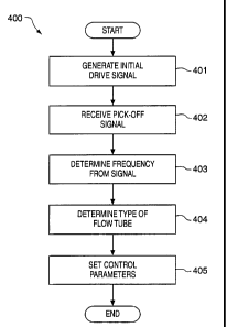
Overview of operation performed by digital transmitter 20- FIG 4
Fig. 4 is an overview of the process perfom~ed by digital transmitter 20 to
initialize the drive signal parameters of Coriolis flowmeter 5125. The above
is a
description of a digital transmitter 20 for a Coriolis flowmeter 5125 and the
following is
a description of the process performed by digital transmitter 20 to provide
the system
7
AMENDED SHEET (ARTICLE 19)
CA 02378004 2005-04-06
for initializing the parameters. One skilled in the art will recognize that it
is possible
to provide the same processes using analog circuitry.
Process 400 begins in step 401 with digital transmitter 20 generating an
initial drive signal. The initial drive signal is applied to the drive circuit
which in turn
applies the initial drive signal to driver 1041204. Driver 1041204 causes the
flow
tubes 103 A-B/ 201 to vibrate. The vibration of the flow tubes is measured by
pick
offs 105-105'1205-205' which apply signals to leads 111-111'1211-211'. The
signals are received then by transmitter 20 in step 402. Transmitter 20
determines
the frequency of oscillation of the flow tubes in step 403. One possible
method for
determining the frequency of oscillation is provided in U.S. patent No:
5,555,190
titled "Method and apparatus for adaptive line enhancement in Coriolis mass
flow
meter measurement," issued to Derby et al. on September 10, 1996 and assigned
to Micro Motion inc. of Boulder Colorado.
In step 404, the type of flow tube is determined by the frequency of
oscillation of the flow tubes. One manner of doing this is to determine
whether the
frequency is greater than a threshold frequency. If the frequency of
oscillation is
above the threshold frequency, the flowmeter is of a straight tube
configuration. If
the frequency is less than or equal to the threshold frequency, the flowmeter
has
flow tubes of a curved configuration. This is known from design analysis and
verified through field experimentations of the flow tubes.
In step 405, control parameters for the drive signals are set in response to a
determination of the type of flowmeter. The following table is an example of
the
parameters set.
Parameter Frequency <= 300 Frequency > 300Hz
Hz
Indicating Curved Indicating Straight
Flow
Configuration Tube Configuration
milliVolts/ Hz 3.4 1.0
8
a
21-06-2001 '010/086W0 , US0016186
~CA 02378004 2001-12-21
Kp, proportional drive1000 2000
gain
K,, integral drive 5 5
gain
MilliVoltsl Hz is a measurement of the drive target or set point. The
proportional drive -
gain target is the amount of millivoltsl Hz needed to drive the flow tubes.
The integral
drive gain is the deviation in millivoltsl Hz that is acceptable for the
signal. In the
preferred exemplary embodiment, it is coincidental that the integral drive
gain is the
same for a straight tube and a dual tube flowmeter.
Process 400 ends after step 405. Transmitter 20 is now able to generate and
maintain a stable drive control of flow tubes 103A-B or 201 based upon the
type of
sensor that is identified in process 400. The stable drive control is
maintained based
upon the unique structural dynamics of the flowmeter and provides optimum
response
time to extraneous input perturbations in the flowmeter.
The above is a description of a system for initializing parameters of a drive
circuit. It is expected that others will design alternative systems and
processes that
infringe on this invention as set forth in the claims below either literally
or through the
Doctrine of Equivalents.
9
AMENDED SHEET (ARTICLE 19)